

Overview
In this article, we will have an overview of the Arduino+PN532 NFC-based board called Maduino Zero NFC Board. The Maduino Zero NFC is an IoT (Internet of things) Solution based on the 32-bit Atmel’s SAMD21 MCU and NXP Near Field Communication Controller PN532. The customized board can be used for payment applications, entrance systems, and security system projects.
The Maduino Zero NFC is based on Arduino and users can program it with Arduino IDE. This guide helps you with the basic usage of Maduino Zero NFC along with hardware overview and programming.
While RFID technology can be used over long distances, NFC technology is limited to small distances. NFC is best used to securely transfer a range of data over short distances, hence its prevalence in access control and payment applications. On the other hand, RFID is more suited to faster-moving environments with lots of moving parts and is most often used for vehicle access control and asset management purposes.
Before moving ahead, check some of our RFID based projects like RFID Security System and also the RFID Attendance System project. You can also check the overview of PN532 NFC Module and its interfacing with Arduino in UART, I2C & SPI Mode.
What is NFC?
NFC, or near-field communication, refers to technology that allows enabled devices that are near each other to wirelessly share data. NFC technology evolved from radio frequency identification (RFID) technology and is more fine-tuned.
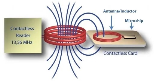
NFC operates on the principle of inductive coupling, at least for short-range implementations. This essentially involves the reader device generating a magnetic field by passing an electric current through a coil. When a tag (with its own coil) is brought nearby, the field induces an electric current within the tag. Then, once the initial handshake is complete, any stored data on the tag is wirelessly transmitted to the reader.
Customized NFC Board (Maduino Zero NFC)
Maduino Zero NFC is an Arduino-compatible small development board with NFC (Near-Field Communication). It is designed using ATSAMD21G18 controller which is actually Arduino Zero board and PN532 NFC Chip.
You can purchase this board from Makerfabs and use it for multipurpose applications.

This board will be the bridge that helps you wirelessly interact with your environment, drive motors, unlock strikes, control relays, read from a temperature sensor. This is because it has built-in NFC connectivity, right out of the box.

This board has a micro USB port for serial communication and supply power. We can connect the 5V power input or a Solar Panel to charge the lipo Battery. It also has a 3.7V LiPo Battery Connector and a power switch to turn ON/OFF the module. An NFC antenna with an IPX interface is used for scanning the NFC tag. A status indicates LED is connected to D2 along with a power indication LED. An SWD switch is available on the board for downloading the bootloader. You can press a reset button on the board to reset the ATSAMD21G18 controller.
At the back of the board there is an SD Card socket. You can insert an SD Card in the socket and store the necessary data in text format.
Features
- ATMEL SAMD21G18A: 32-bit ARM® Cortex®-M0 up to 48MHz, 256KB flash, 32KB SRAM, LQFP48
- Powered by a lithium battery(3.4-4.2V) Or MicroUSB
- NXP PN532, Near Field Communication (NFC) controller
- Contactless communication at 13.56 MHz
- PCD mode for FeliCa, ISO/IEC14443-3 Type-A, Mifare, ISO/IEC14443-4 Type-A, and Innovision Jewel cards
- Interface: I2C/SPI/UART/ADC/DAC/I2S/38*GPIO
- Arduino Compatible: You can play it with Arduino IDE
- More cost-effective and high quality than Arduino Zero
- Default baud rate: 115200bps
Warning: Don’t operate when in power supply on (That is, don’t plug or unplug the Antenna, SD Card, in case of short-circuiting that may burn the IC down.)
How to use Maduino NFC Board?
The Maduino NFC Board has a Arduino Zero controller PN532 NFC Chip. To use this board with Arduino IDE, we need to setup Arduino IDE first.
Setting up Arduino IDE
The ATSAMD21G18A board isn’t pre-installed in the Arduino IDE. So, we need to install “Arduino Zero Board” from the Board Manager.
Open the Boards Manager From the top Arduino IDE menu, select Tools-> Board-> Boards Manager… to open the Boards Manager dialog box. Then install Arduino SAMD Boards(32-bits ARM Cortex-M0+).

Once, the installation completes, you can now select the Arduino Zero board as shown in the image below. To program this Board you need to connect a Micro USB Data Cable.

Hardware Connections
First Plug a NFC Antenna to designator which shows ANT1. Then plug a Micro USB Cable to Maduino Zero NFC. You can connect a 0.96″ I2C OLED Display to the board via a 4 pin female header.
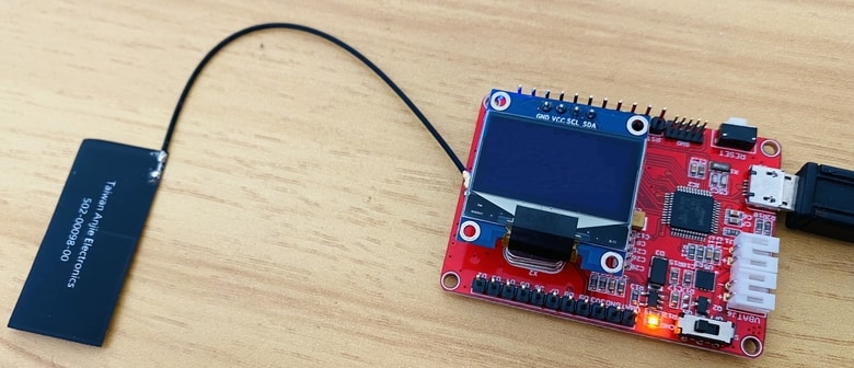
You can supply power with a 3.7V lithium battery after you upload the program to the board as it works between 3.4V to 4.2V. Both the battery and the MicroUSB can be used for the power supply. While MicroUSB is connected, the board will be powered by MicroUSB, while MicroUSB removed, it will switch to battery automatically.
Source Code & Programming
Select the Arduino Zero(Native USB port) board from the Arduino IDE Board menu. Then select the correct Port number as Native USB port will appear in the COM port. Now you can upload the following code to the Maduino Board.
But the Arduino IDE requires some library for compilation. Download the following libraries and add them to the Arduino IDE via Library Manager:
1. Adafruit PN532 Library: Download
2. Adafruit GFX Library: https://github.com/adafruit/Adafruit-GFX-Library
3. SSD1306 OLED Library: Download
This is the complete Arduino PN532 NFC interface code.
|
1 2 3 4 5 6 7 8 9 10 11 12 13 14 15 16 17 18 19 20 21 22 23 24 25 26 27 28 29 30 31 32 33 34 35 36 37 38 39 40 41 42 43 44 45 46 47 48 49 50 51 52 53 54 55 56 57 58 59 60 61 62 63 64 65 66 67 68 69 70 71 72 73 74 75 76 77 78 79 80 81 82 83 84 85 86 87 88 89 90 91 92 93 94 95 96 97 98 99 100 101 102 103 104 105 106 107 108 109 110 111 112 113 114 115 116 117 118 119 120 121 122 123 124 125 126 127 128 129 130 131 132 133 134 135 136 137 138 139 140 141 142 143 |
#include <Wire.h> #include <SPI.h> #include "Adafruit_PN532.h" #include <Adafruit_GFX.h> #include <Adafruit_SSD1306.h> #define PN532_SS (9) #define PN532_IRQ (2) #define PN532_RESET (11) // Not connected by default on the NFC Shield #define SCREEN_WIDTH 128 // OLED display width, in pixels #define SCREEN_HEIGHT 64 // OLED display height, in pixels #define OLED_RESET 4 // Reset pin # (or -1 if sharing Arduino reset pin) #define SCREEN_ADDRESS 0x3C ///< See datasheet for Address; 0x3D for 128x64, 0x3C for 128x32 Adafruit_PN532 nfc(PN532_SS); Adafruit_SSD1306 display(SCREEN_WIDTH, SCREEN_HEIGHT, &Wire, OLED_RESET); #if defined(ARDUINO_ARCH_SAMD) #define Serial SerialUSB #endif #define STA_LED 2 //D2 void setup(void) { pinMode(STA_LED, OUTPUT); digitalWrite(STA_LED, HIGH); // turn the LED off (HIGH is the voltage level) #ifndef ESP8266 while (!Serial); // for Leonardo/Micro/Zero #endif Serial.begin(115200); SerialUSB.begin(115200); if (!display.begin(SSD1306_SWITCHCAPVCC, SCREEN_ADDRESS)) { Serial.println(F("SSD1306 allocation failed")); for (;;); // Don't proceed, loop forever } nfc.begin(); uint32_t versiondata = nfc.getFirmwareVersion(); if (! versiondata) { SerialUSB.print("Didn't find PN53x board"); while (1); // halt } // Got ok data, print it out! SerialUSB.print("Found chip PN5"); SerialUSB.println((versiondata >> 24) & 0xFF, HEX); SerialUSB.print("Firmware ver. "); SerialUSB.print((versiondata >> 16) & 0xFF, DEC); SerialUSB.print('.'); SerialUSB.println((versiondata >> 8) & 0xFF, DEC); display.clearDisplay(); display.setCursor(0, 0); //oled display display.setTextSize(1); display.setTextColor(WHITE); display.print("Found chip PN5"); display.print((versiondata >> 24) & 0xFF, HEX); display.setCursor(0, 20); //oled display display.setTextSize(1); display.setTextColor(WHITE); display.print("Firmware ver. "); display.print((versiondata >> 16) & 0xFF, DEC); display.print("."); display.print((versiondata >> 8) & 0xFF, DEC); nfc.setPassiveActivationRetries(0xFF); // configure board to read RFID tags nfc.SAMConfig(); SerialUSB.println("Waiting for an ISO14443A card"); display.setCursor(0, 40); //oled display display.setTextSize(1); display.setTextColor(WHITE); display.print("Waiting for NFC Card"); display.display(); } void loop(void) { boolean result_success = 0; uint8_t uid[] = { 0, 0, 0, 0, 0, 0, 0 }; // Buffer to store the returned UID uint8_t uidLength; // Length of the UID (4 or 7 bytes depending on ISO14443A card type) result_success = nfc.readPassiveTargetID(PN532_MIFARE_ISO14443A, &uid[0], &uidLength); if (result_success) { SerialUSB.println("Found a card!"); SerialUSB.print("UID Length: "); SerialUSB.print(uidLength, DEC); SerialUSB.println(" bytes"); SerialUSB.print("UID Value: "); display.clearDisplay(); display.setCursor(10, 0); //oled display display.setTextSize(1); display.setTextColor(WHITE); display.print("UID Length:"); display.print(uidLength, DEC); display.print(" bytes"); display.setCursor(35, 20); //oled display display.setTextSize(1); display.setTextColor(WHITE); display.println("UID Value: "); display.setCursor(5, 35); //oled display for (uint8_t i = 0; i < uidLength; i++) { SerialUSB.print("0x"); SerialUSB.print(uid[i], HEX); display.print(" 0x"); display.print(uid[i], HEX); display.display(); } SerialUSB.println(""); digitalWrite(STA_LED, LOW);// turn the LED on (LOW is the voltage level) result_success = 0; // Wait 1 second before continuing delay(1000); } else { // PN532 probably timed out waiting for a card SerialUSB.println("Timed out waiting for a card"); } digitalWrite(STA_LED, HIGH); // turn the LED off (HIGH is the voltage level) } |
Testing & Results
After code uploads successfully, you can start the testing process. The OLED Display will print firmware version as 1.6 and will ask to scan the cards.

Now bring some NFC Cards near the Antenna of Maduino Zero Board. The NFC Card may include your bank card or a travel card or maybe some NFC test Card.

When you put the card on the top of the antenna, it will read byte length along with the UID value & displays them on the OLED screen.

Sometimes the byte length might be 4 bytes or 7 bytes depending upon the type of NFC Card.

In case you don’t want the OLED Display for the project, you can display the UID value and byte length on the Serial Monitor.

This is how you can use Arduino & PN532 NFC based Maduino Zero NFC Board for payment, entrance & security System applications.
Video Tutorial & Guide


")


2 Comments
May you please do a full video tutorial on door access with the above board
Yes some videos are coming soon.