

Overview
In this project, we will build a data logger using Micro SD Card & Raspberry Pi Pico. We will use a DHT11 Sensor to read the Humidity and Temperature data. The programming will be done in Thonny IDE using MicroPython Code. The temperature humidity data read will be stored in SD Card. Hence this can be useful in data logging.
In previous project, we learned Interfacing of SD Card Module with Raspberry Pi Pico Board. We will just modify the previous code and also add reading of DHT11 Sensor data. Thus DHT11 Data will be saved in SD Card over a period of time. It keeps track of the temperature and humidity levels in our surroundings. It can record environmental data over time, helping us monitor our surroundings.
Bill of Materials
For this tutorial, we recommend to buy the following list of components directly from given links.
| S.N. | Components Name | Quantity | Purchase Links |
|---|---|---|---|
| 1 | Raspberry Pi Pico | 1 | Amazon | AliExpress | SunFounder |
| 2 | SD Card Module | 1 | Amazon | AliExpress | SunFounder |
| 3 | SD Card 4-16 GB | 1 | Amazon | AliExpress | SunFounder |
| 4 | USB Card Reader | 1 | Amazon | AliExpress | SunFounder |
| 5 | DHT11 Sensor | 1 | Amazon | AliExpress| SunFounder |
| 6 | Jumper Wires | 10 | Amazon | AliExpress | SunFounder |
Preparing the Micro SD Card

Before you insert the micro SD card into the module, you must properly format the card. You should format the SD card as FAT16 or FAT32.

To format the SD card, insert it into your computer. Go to My Computer and right-click on the SD card. A new window pops up. Select FAT32 as a Formatting option. Then press Start to initialize the formatting process

The SD Card has been successfully formatted. You can now utilize it with the SD Card Module for your project applications.
Circuit: Data Logger with SD Card & Raspberry Pi Pico
Let us take a look at the connection diagram of Data Logger with SD Card & Raspberry Pi Pico.

Connect the SD Card Module to Raspberry Pi Pico as per the above Circuit Diagram. For Raspberry Pi Pico board, the SPI pins we can use are 2 (SCK), 4 (MISO), 3 (MOSI) and 1 (CS).
For the DHT11 Part, connect the VCC, GND & Output to the 3.3V, GND & GP5 of Raspberry Pi Pico. You may check the DHT11 Raspberry Pi Pico interfacing guide.

You may use a breadboard for assembly and troubleshooting.
MicroPython Code
The code for Data Logger with SD Card & Raspberry Pi Pico has been written in MicroPython. Hence you need a MicroPython Compiler like Thonny IDE.
For this project, we need dht11 MicroPython Library and also the SD Card MicroPython Library. Hence it is necessary to first save these two libraries in the Raspberry Pi Pico Board.
dht.py
Copy the following code in the Thonny Editor and save it with name dht.py in Raspberry Pi Pico.
|
1 2 3 4 5 6 7 8 9 10 11 12 13 14 15 16 17 18 19 20 21 22 23 24 25 26 27 28 29 30 31 32 33 34 35 36 37 38 39 40 41 42 43 44 45 46 47 48 49 50 51 52 53 54 55 56 57 58 59 60 61 62 63 64 65 66 67 68 69 70 71 72 73 74 75 76 77 78 79 80 81 82 83 84 85 86 87 88 89 90 91 92 93 94 95 96 97 98 99 100 101 102 103 104 105 106 107 108 109 110 111 112 113 114 115 116 117 118 119 120 121 122 123 124 125 126 127 128 |
import array import micropython import utime from machine import Pin from micropython import const class InvalidChecksum(Exception): pass class InvalidPulseCount(Exception): pass MAX_UNCHANGED = const(100) MIN_INTERVAL_US = const(200000) HIGH_LEVEL = const(50) EXPECTED_PULSES = const(84) class DHT11: _temperature: int _humidity: int def __init__(self, pin): self._pin = pin self._last_measure = utime.ticks_us() self._temperature = -1 self._humidity = -1 def measure(self): current_ticks = utime.ticks_us() if utime.ticks_diff(current_ticks, self._last_measure) < MIN_INTERVAL_US and ( self._temperature > -1 or self._humidity > -1 ): # Less than a second since last read, which is too soon according # to the datasheet return self._send_init_signal() pulses = self._capture_pulses() buffer = self._convert_pulses_to_buffer(pulses) self._verify_checksum(buffer) self._humidity = buffer[0] + buffer[1] / 10 self._temperature = buffer[2] + buffer[3] / 10 self._last_measure = utime.ticks_us() @property def humidity(self): self.measure() return self._humidity @property def temperature(self): self.measure() return self._temperature def _send_init_signal(self): self._pin.init(Pin.OUT, Pin.PULL_DOWN) self._pin.value(1) utime.sleep_ms(50) self._pin.value(0) utime.sleep_ms(18) @micropython.native def _capture_pulses(self): pin = self._pin pin.init(Pin.IN, Pin.PULL_UP) val = 1 idx = 0 transitions = bytearray(EXPECTED_PULSES) unchanged = 0 timestamp = utime.ticks_us() while unchanged < MAX_UNCHANGED: if val != pin.value(): if idx >= EXPECTED_PULSES: raise InvalidPulseCount( "Got more than {} pulses".format(EXPECTED_PULSES) ) now = utime.ticks_us() transitions[idx] = now - timestamp timestamp = now idx += 1 val = 1 - val unchanged = 0 else: unchanged += 1 pin.init(Pin.OUT, Pin.PULL_DOWN) if idx != EXPECTED_PULSES: raise InvalidPulseCount( "Expected {} but got {} pulses".format(EXPECTED_PULSES, idx) ) return transitions[4:] def _convert_pulses_to_buffer(self, pulses): """Convert a list of 80 pulses into a 5 byte buffer The resulting 5 bytes in the buffer will be: 0: Integral relative humidity data 1: Decimal relative humidity data 2: Integral temperature data 3: Decimal temperature data 4: Checksum """ # Convert the pulses to 40 bits binary = 0 for idx in range(0, len(pulses), 2): binary = binary << 1 | int(pulses[idx] > HIGH_LEVEL) # Split into 5 bytes buffer = array.array("B") for shift in range(4, -1, -1): buffer.append(binary >> shift * 8 & 0xFF) return buffer def _verify_checksum(self, buffer): # Calculate checksum checksum = 0 for buf in buffer[0:4]: checksum += buf if checksum & 0xFF != buffer[4]: raise InvalidChecksum() |
sdcard.py
Now copy the following code to Thonny editor and save it with name sdcard.py.
|
1 2 3 4 5 6 7 8 9 10 11 12 13 14 15 16 17 18 19 20 21 22 23 24 25 26 27 28 29 30 31 32 33 34 35 36 37 38 39 40 41 42 43 44 45 46 47 48 49 50 51 52 53 54 55 56 57 58 59 60 61 62 63 64 65 66 67 68 69 70 71 72 73 74 75 76 77 78 79 80 81 82 83 84 85 86 87 88 89 90 91 92 93 94 95 96 97 98 99 100 101 102 103 104 105 106 107 108 109 110 111 112 113 114 115 116 117 118 119 120 121 122 123 124 125 126 127 128 129 130 131 132 133 134 135 136 137 138 139 140 141 142 143 144 145 146 147 148 149 150 151 152 153 154 155 156 157 158 159 160 161 162 163 164 165 166 167 168 169 170 171 172 173 174 175 176 177 178 179 180 181 182 183 184 185 186 187 188 189 190 191 192 193 194 195 196 197 198 199 200 201 202 203 204 205 206 207 208 209 210 211 212 213 214 215 216 217 218 219 220 221 222 223 224 225 226 227 228 229 230 231 232 233 234 235 236 237 238 239 240 241 242 243 244 245 246 247 248 249 250 251 252 253 254 255 256 257 258 259 260 261 262 263 264 265 266 267 268 269 270 271 272 273 274 275 276 277 278 279 280 281 282 283 284 285 286 287 288 289 290 291 292 293 294 295 296 297 298 299 300 301 |
""" MicroPython driver for SD cards using SPI bus. Origial: https://github.com/micropython/micropython/tree/master/drivers/sdcard RAW: https://raw.githubusercontent.com/micropython/micropython/master/drivers/sdcard/sdcard.py Requires an SPI bus and a CS pin. Provides readblocks and writeblocks methods so the device can be mounted as a filesystem. Example usage on pyboard: import pyb, sdcard, os sd = sdcard.SDCard(pyb.SPI(1), pyb.Pin.board.X5) pyb.mount(sd, '/sd2') os.listdir('/') Example usage on ESP8266: import machine, sdcard, os sd = sdcard.SDCard(machine.SPI(1), machine.Pin(15)) os.mount(sd, '/sd') os.listdir('/') """ from micropython import const import time _CMD_TIMEOUT = const(100) _R1_IDLE_STATE = const(1 << 0) # R1_ERASE_RESET = const(1 << 1) _R1_ILLEGAL_COMMAND = const(1 << 2) # R1_COM_CRC_ERROR = const(1 << 3) # R1_ERASE_SEQUENCE_ERROR = const(1 << 4) # R1_ADDRESS_ERROR = const(1 << 5) # R1_PARAMETER_ERROR = const(1 << 6) _TOKEN_CMD25 = const(0xFC) _TOKEN_STOP_TRAN = const(0xFD) _TOKEN_DATA = const(0xFE) class SDCard: def __init__(self, spi, cs, baudrate=1320000): self.spi = spi self.cs = cs self.cmdbuf = bytearray(6) self.dummybuf = bytearray(512) self.tokenbuf = bytearray(1) for i in range(512): self.dummybuf[i] = 0xFF self.dummybuf_memoryview = memoryview(self.dummybuf) # initialise the card self.init_card(baudrate) def init_spi(self, baudrate): try: master = self.spi.MASTER except AttributeError: # on ESP8266 self.spi.init(baudrate=baudrate, phase=0, polarity=0) else: # on pyboard self.spi.init(master, baudrate=baudrate, phase=0, polarity=0) def init_card(self, baudrate): # init CS pin self.cs.init(self.cs.OUT, value=1) # init SPI bus; use low data rate for initialisation self.init_spi(100000) # clock card at least 100 cycles with cs high for i in range(16): self.spi.write(b"\xff") # CMD0: init card; should return _R1_IDLE_STATE (allow 5 attempts) for _ in range(5): if self.cmd(0, 0, 0x95) == _R1_IDLE_STATE: break else: raise OSError("no SD card") # CMD8: determine card version r = self.cmd(8, 0x01AA, 0x87, 4) if r == _R1_IDLE_STATE: self.init_card_v2() elif r == (_R1_IDLE_STATE | _R1_ILLEGAL_COMMAND): self.init_card_v1() else: raise OSError("couldn't determine SD card version") # get the number of sectors # CMD9: response R2 (R1 byte + 16-byte block read) if self.cmd(9, 0, 0, 0, False) != 0: raise OSError("no response from SD card") csd = bytearray(16) self.readinto(csd) if csd[0] & 0xC0 == 0x40: # CSD version 2.0 self.sectors = ((csd[8] << 8 | csd[9]) + 1) * 1024 elif csd[0] & 0xC0 == 0x00: # CSD version 1.0 (old, <=2GB) c_size = (csd[6] & 0b11) << 10 | csd[7] << 2 | csd[8] >> 6 c_size_mult = (csd[9] & 0b11) << 1 | csd[10] >> 7 read_bl_len = csd[5] & 0b1111 capacity = (c_size + 1) * (2 ** (c_size_mult + 2)) * (2**read_bl_len) self.sectors = capacity // 512 else: raise OSError("SD card CSD format not supported") # print('sectors', self.sectors) # CMD16: set block length to 512 bytes if self.cmd(16, 512, 0) != 0: raise OSError("can't set 512 block size") # set to high data rate now that it's initialised self.init_spi(baudrate) def init_card_v1(self): for i in range(_CMD_TIMEOUT): self.cmd(55, 0, 0) if self.cmd(41, 0, 0) == 0: # SDSC card, uses byte addressing in read/write/erase commands self.cdv = 512 # print("[SDCard] v1 card") return raise OSError("timeout waiting for v1 card") def init_card_v2(self): for i in range(_CMD_TIMEOUT): time.sleep_ms(50) self.cmd(58, 0, 0, 4) self.cmd(55, 0, 0) if self.cmd(41, 0x40000000, 0) == 0: self.cmd(58, 0, 0, -4) # 4-byte response, negative means keep the first byte ocr = self.tokenbuf[0] # get first byte of response, which is OCR if not ocr & 0x40: # SDSC card, uses byte addressing in read/write/erase commands self.cdv = 512 else: # SDHC/SDXC card, uses block addressing in read/write/erase commands self.cdv = 1 # print("[SDCard] v2 card") return raise OSError("timeout waiting for v2 card") def cmd(self, cmd, arg, crc, final=0, release=True, skip1=False): self.cs(0) # create and send the command buf = self.cmdbuf buf[0] = 0x40 | cmd buf[1] = arg >> 24 buf[2] = arg >> 16 buf[3] = arg >> 8 buf[4] = arg buf[5] = crc self.spi.write(buf) if skip1: self.spi.readinto(self.tokenbuf, 0xFF) # wait for the response (response[7] == 0) for i in range(_CMD_TIMEOUT): self.spi.readinto(self.tokenbuf, 0xFF) response = self.tokenbuf[0] if not (response & 0x80): # this could be a big-endian integer that we are getting here # if final<0 then store the first byte to tokenbuf and discard the rest if final < 0: self.spi.readinto(self.tokenbuf, 0xFF) final = -1 - final for j in range(final): self.spi.write(b"\xff") if release: self.cs(1) self.spi.write(b"\xff") return response # timeout self.cs(1) self.spi.write(b"\xff") return -1 def readinto(self, buf): self.cs(0) # read until start byte (0xff) for i in range(_CMD_TIMEOUT): self.spi.readinto(self.tokenbuf, 0xFF) if self.tokenbuf[0] == _TOKEN_DATA: break time.sleep_ms(1) else: self.cs(1) raise OSError("timeout waiting for response") # read data mv = self.dummybuf_memoryview if len(buf) != len(mv): mv = mv[: len(buf)] self.spi.write_readinto(mv, buf) # read checksum self.spi.write(b"\xff") self.spi.write(b"\xff") self.cs(1) self.spi.write(b"\xff") def write(self, token, buf): self.cs(0) # send: start of block, data, checksum self.spi.read(1, token) self.spi.write(buf) self.spi.write(b"\xff") self.spi.write(b"\xff") # check the response if (self.spi.read(1, 0xFF)[0] & 0x1F) != 0x05: self.cs(1) self.spi.write(b"\xff") return # wait for write to finish while self.spi.read(1, 0xFF)[0] == 0: pass self.cs(1) self.spi.write(b"\xff") def write_token(self, token): self.cs(0) self.spi.read(1, token) self.spi.write(b"\xff") # wait for write to finish while self.spi.read(1, 0xFF)[0] == 0x00: pass self.cs(1) self.spi.write(b"\xff") def readblocks(self, block_num, buf): nblocks = len(buf) // 512 assert nblocks and not len(buf) % 512, "Buffer length is invalid" if nblocks == 1: # CMD17: set read address for single block if self.cmd(17, block_num * self.cdv, 0, release=False) != 0: # release the card self.cs(1) raise OSError(5) # EIO # receive the data and release card self.readinto(buf) else: # CMD18: set read address for multiple blocks if self.cmd(18, block_num * self.cdv, 0, release=False) != 0: # release the card self.cs(1) raise OSError(5) # EIO offset = 0 mv = memoryview(buf) while nblocks: # receive the data and release card self.readinto(mv[offset : offset + 512]) offset += 512 nblocks -= 1 if self.cmd(12, 0, 0xFF, skip1=True): raise OSError(5) # EIO def writeblocks(self, block_num, buf): nblocks, err = divmod(len(buf), 512) assert nblocks and not err, "Buffer length is invalid" if nblocks == 1: # CMD24: set write address for single block if self.cmd(24, block_num * self.cdv, 0) != 0: raise OSError(5) # EIO # send the data self.write(_TOKEN_DATA, buf) else: # CMD25: set write address for first block if self.cmd(25, block_num * self.cdv, 0) != 0: raise OSError(5) # EIO # send the data offset = 0 mv = memoryview(buf) while nblocks: self.write(_TOKEN_CMD25, mv[offset : offset + 512]) offset += 512 nblocks -= 1 self.write_token(_TOKEN_STOP_TRAN) def ioctl(self, op, arg): if op == 4: # get number of blocks return self.sectors if op == 5: # get block size in bytes return 512 |
main.py
Here is the main.py code for making the Data Logger with SD Card & Raspberry Pi Pico using MicroPython Code. Copy the following code to the Thonny editor and save it with name main.py.
|
1 2 3 4 5 6 7 8 9 10 11 12 13 14 15 16 17 18 19 20 21 22 23 24 25 26 27 28 29 30 31 32 33 34 35 36 37 38 39 40 41 42 43 44 45 46 47 48 49 50 51 |
import machine import sdcard import uos import dht import utime # DHT11 data pin dht_sensor = dht.DHT11(machine.Pin(5)) # Assign chip select (CS) pin (and start it high) cs = machine.Pin(1, machine.Pin.OUT) # Initialize SPI peripheral (start with 1 MHz) spi = machine.SPI(0, baudrate=1000000, polarity=0, phase=0, bits=8, firstbit=machine.SPI.MSB, sck=machine.Pin(2), mosi=machine.Pin(3), miso=machine.Pin(4)) # Initialize SD card sd = sdcard.SDCard(spi, cs) # Mount filesystem vfs = uos.VfsFat(sd) uos.mount(vfs, "/sd") # Run this in an infinite loop to continuously log sensor data while True: try: dht_sensor.measure() temp = dht_sensor.temperature # No parentheses here humidity = dht_sensor.humidity # No parentheses here # Create a file and write the sensor readings to it with open("/sd/sensor_log.txt", "a") as file: file.write("Temperature: {}C, Humidity: {}%\r\n".format(temp, humidity)) # Open the file we just created and read from it with open("/sd/sensor_log.txt", "r") as file: data = file.read() print(data) except Exception as e: print('Failed to read sensor.', e) # Sleep for 1 minute before next reading utime.sleep(5) |
Testing & Results
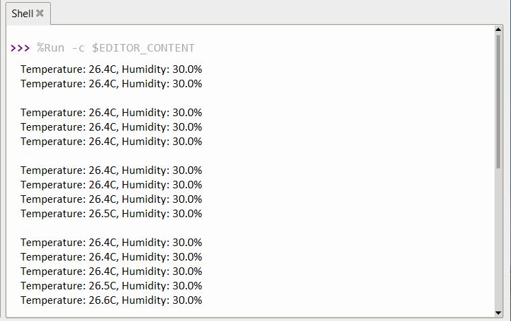
After all the files are saved in Raspberry Pi Pico, you can run the code, the Thonny Shell will start displaying the temperature and Humidity data saved in Raspberry Pi Pico.
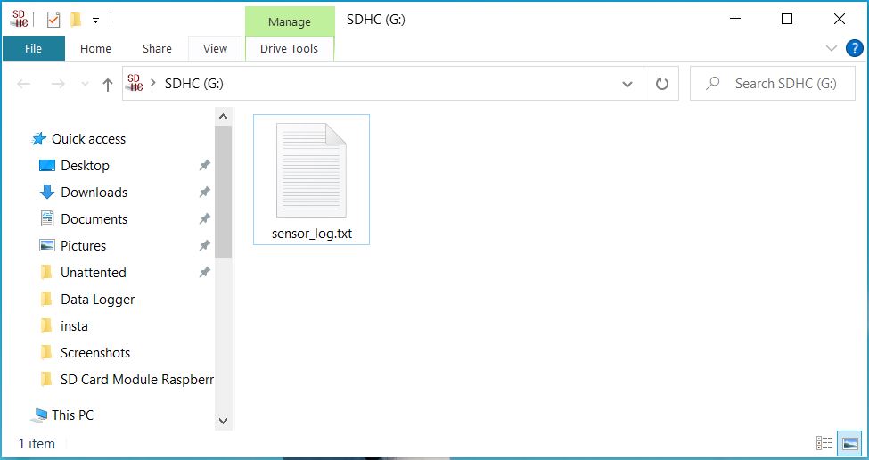
You can check the stored data on your computer. For that remove the SD Card from SD Card Module and put it into the SD Card Adapter. Then open the SD Card on your computer. A file named sensor_log.txt will appear.
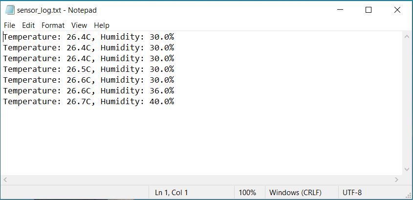
Open the file using text editor and you will see Sensor data logged in to the file.
This is how you can interface SD Card with Raspberry Pi Pico using MicroPython Code and use it as a Data Logger.
Conclusion
In conclusion, we have successfully developed a data logger using a Micro SD Card and Raspberry Pi Pico. With the integration of the DHT11 Sensor, we were able to read and log humidity and temperature data. Programming this project in Thonny IDE with MicroPython Code facilitated the process, and allowed us to store this environmental data directly on the SD Card. The collected DHT11 data provides a valuable record of temperature and humidity changes over time, serving as a practical tool for environmental monitoring. Through this project, we have demonstrated the potential uses of data logging in tracking and understanding our surroundings.


2 Comments
It’s a cool project. Here, if I want to record the water height with the ultrasonic sensor, what should be done in the code? If we could send data to lorawan gateway with ra-08h, it would be a complete project. Thanks.
Thank you for sharing this nice project.
If it is possible that each line with temperature and humidity can be logged with the date/time of a DS3231 real time clock module, then you can do much more with the data to analyze at a later moment.
I have puzzled a bit but some assistance is very welcome.
Thank you in advance!