

Overview
In this tutorial we will learn Interfacing of DHT11 Temperature Humidity Sensor with Raspberry Pi Pico. We will write a MicroPython code for DHT11 Sensor. We will use 0.96″ I2C OLED Display and disply the DHT11 temperature and Humidity value on it.
The DHT11 is a basic, ultra low-cost digital temperature and humidity sensor. It uses a capacitive humidity sensor and a thermistor to measure the surrounding air. This sensor can be easily interfaced with any microcontroller such as Arduino or RP2040 Raspberry Pi Pico to measure humidity and temperature instantaneously. You can make a Weather Station project with DHT11 Sensor.
This post explains, the method of retrieving the Humidity & Temperature data from the DHT11 sensor using Raspberry Pi Pico & MicroPython Code. The retrieved data will be displayed on Python Shell Window and later on OLED Display. But before moving ahead, please follow the Raspberry Pi Pico Getting Started Tutorial to learn more about the Pico Board in detail.
Bill of Materials
The list of components that you need for this project is given below. You can purchase all the components from Amazon.
| S.N. | Components Name | Quantity | Purchase Links |
|---|---|---|---|
| 1 | Raspberry Pi Pico | 1 | Amazon | AliExpress |
| 2 | 0.96" I2C OLED Display | 1 | Amazon | AliExpress |
| 3 | DHT11 Sensor | 1 | Amazon | AliExpress |
| 4 | Jumper Wires | 1 | Amazon | AliExpress |
| 5 | Breadboard | 1 | Amazon | AliExpress |
DHT11 Humidity Temperature Sensor
The DHT11 is a basic, ultra low-cost digital temperature and humidity sensor. It uses a capacitive humidity sensor and a thermistor to measure the surrounding air and spits out a digital signal on the data pin (no analog input pins needed). The temperature range of DHT11 is from 0 to 50 degrees Celsius with a 2-degree accuracy. The humidity range of this sensor is from 20 to 80% with 5% accuracy.

DHT11 sensor has four pins- VCC, GND, Data Pin, and a not connected pin. A pull-up resistor of 5k to 10k ohms is provided for communication between sensor and micro-controller.
It’s fairly simple to use, but requires careful timing to grab data. The only real downside of this sensor is you can only get new data from it once every 2 seconds, so when using the library, sensor readings can be up to 2 seconds old. To learn more about the DHT11 Sensor, you can check the DHT11 Datasheet.
Setting up DHT11 Sensor with Raspberry Pi Pico
The hardware setup and hookup guide for DHT11 Sensor with Raspberry Pi Pico board & OLED Display is super easy. The connection diagram is given below.

Connect the DHT11 digital output pin to GP28 of Pico Board. Connect the SCL & SDA pin of OLED Display to Raspberry Pi Pico GP9 & GP8 Pin. Supply DHT11 & OLED Display with 3.3V VCC & Connect their GND pins to Pico GND Pin.

DHT11 Raspberry Pi Pico MicroPython Code
The DHT11 MicroPython Code for Raspberry Pi Pico comprises of so many dependencies. We have to write MicroPython code for the DHT11 Library and also for the OLED Display.
The code comprises of 3 parts:
1. SSD1306.py
2. dht.py
3. main.py
SSD1306.py
First open a New Tab, and copy the following code. Save the file with the name SSD1306.py & then run or download it to the Raspberry Pi Pico Board.
|
1 2 3 4 5 6 7 8 9 10 11 12 13 14 15 16 17 18 19 20 21 22 23 24 25 26 27 28 29 30 31 32 33 34 35 36 37 38 39 40 41 42 43 44 45 46 47 48 49 50 51 52 53 54 55 56 57 58 59 60 61 62 63 64 65 66 67 68 69 70 71 72 73 74 75 76 77 78 79 80 81 82 83 84 85 86 87 88 89 90 91 92 93 94 95 96 97 98 99 100 101 102 103 104 105 106 107 108 109 110 111 112 113 114 115 116 117 118 119 120 121 122 123 124 125 126 127 128 129 130 131 132 133 134 135 136 137 138 139 140 141 142 143 144 145 146 147 148 149 150 151 152 153 154 155 |
# MicroPython SSD1306 OLED driver, I2C and SPI interfaces from micropython import const import framebuf # register definitions SET_CONTRAST = const(0x81) SET_ENTIRE_ON = const(0xA4) SET_NORM_INV = const(0xA6) SET_DISP = const(0xAE) SET_MEM_ADDR = const(0x20) SET_COL_ADDR = const(0x21) SET_PAGE_ADDR = const(0x22) SET_DISP_START_LINE = const(0x40) SET_SEG_REMAP = const(0xA0) SET_MUX_RATIO = const(0xA8) SET_COM_OUT_DIR = const(0xC0) SET_DISP_OFFSET = const(0xD3) SET_COM_PIN_CFG = const(0xDA) SET_DISP_CLK_DIV = const(0xD5) SET_PRECHARGE = const(0xD9) SET_VCOM_DESEL = const(0xDB) SET_CHARGE_PUMP = const(0x8D) # Subclassing FrameBuffer provides support for graphics primitives # http://docs.micropython.org/en/latest/pyboard/library/framebuf.html class SSD1306(framebuf.FrameBuffer): def __init__(self, width, height, external_vcc): self.width = width self.height = height self.external_vcc = external_vcc self.pages = self.height // 8 self.buffer = bytearray(self.pages * self.width) super().__init__(self.buffer, self.width, self.height, framebuf.MONO_VLSB) self.init_display() def init_display(self): for cmd in ( SET_DISP | 0x00, # off # address setting SET_MEM_ADDR, 0x00, # horizontal # resolution and layout SET_DISP_START_LINE | 0x00, SET_SEG_REMAP | 0x01, # column addr 127 mapped to SEG0 SET_MUX_RATIO, self.height - 1, SET_COM_OUT_DIR | 0x08, # scan from COM[N] to COM0 SET_DISP_OFFSET, 0x00, SET_COM_PIN_CFG, 0x02 if self.width > 2 * self.height else 0x12, # timing and driving scheme SET_DISP_CLK_DIV, 0x80, SET_PRECHARGE, 0x22 if self.external_vcc else 0xF1, SET_VCOM_DESEL, 0x30, # 0.83*Vcc # display SET_CONTRAST, 0xFF, # maximum SET_ENTIRE_ON, # output follows RAM contents SET_NORM_INV, # not inverted # charge pump SET_CHARGE_PUMP, 0x10 if self.external_vcc else 0x14, SET_DISP | 0x01, ): # on self.write_cmd(cmd) self.fill(0) self.show() def poweroff(self): self.write_cmd(SET_DISP | 0x00) def poweron(self): self.write_cmd(SET_DISP | 0x01) def contrast(self, contrast): self.write_cmd(SET_CONTRAST) self.write_cmd(contrast) def invert(self, invert): self.write_cmd(SET_NORM_INV | (invert & 1)) def show(self): x0 = 0 x1 = self.width - 1 if self.width == 64: # displays with width of 64 pixels are shifted by 32 x0 += 32 x1 += 32 self.write_cmd(SET_COL_ADDR) self.write_cmd(x0) self.write_cmd(x1) self.write_cmd(SET_PAGE_ADDR) self.write_cmd(0) self.write_cmd(self.pages - 1) self.write_data(self.buffer) class SSD1306_I2C(SSD1306): def __init__(self, width, height, i2c, addr=0x3C, external_vcc=False): self.i2c = i2c self.addr = addr self.temp = bytearray(2) self.write_list = [b"\x40", None] # Co=0, D/C#=1 super().__init__(width, height, external_vcc) def write_cmd(self, cmd): self.temp[0] = 0x80 # Co=1, D/C#=0 self.temp[1] = cmd self.i2c.writeto(self.addr, self.temp) def write_data(self, buf): self.write_list[1] = buf self.i2c.writevto(self.addr, self.write_list) class SSD1306_SPI(SSD1306): def __init__(self, width, height, spi, dc, res, cs, external_vcc=False): self.rate = 10 * 1024 * 1024 dc.init(dc.OUT, value=0) res.init(res.OUT, value=0) cs.init(cs.OUT, value=1) self.spi = spi self.dc = dc self.res = res self.cs = cs import time self.res(1) time.sleep_ms(1) self.res(0) time.sleep_ms(10) self.res(1) super().__init__(width, height, external_vcc) def write_cmd(self, cmd): self.spi.init(baudrate=self.rate, polarity=0, phase=0) self.cs(1) self.dc(0) self.cs(0) self.spi.write(bytearray([cmd])) self.cs(1) def write_data(self, buf): self.spi.init(baudrate=self.rate, polarity=0, phase=0) self.cs(1) self.dc(1) self.cs(0) self.spi.write(buf) self.cs(1) |
dht.py
After uploading the SSD1306 program, open a New Tab again and copy the following code. Save the file with the name dht.py & then run or download it to the Raspberry Pi Pico Board.
|
1 2 3 4 5 6 7 8 9 10 11 12 13 14 15 16 17 18 19 20 21 22 23 24 25 26 27 28 29 30 31 32 33 34 35 36 37 38 39 40 41 42 43 44 45 46 47 48 49 50 51 52 53 54 55 56 57 58 59 60 61 62 63 64 65 66 67 68 69 70 71 72 73 74 75 76 77 78 79 80 81 82 83 84 85 86 87 88 89 90 91 92 93 94 95 96 97 98 99 100 101 102 103 104 105 106 107 108 109 110 111 112 113 114 115 116 117 118 119 120 121 122 |
import array import micropython import utime from machine import Pin from micropython import const class InvalidChecksum(Exception): pass class InvalidPulseCount(Exception): pass MAX_UNCHANGED = const(100) MIN_INTERVAL_US = const(200000) HIGH_LEVEL = const(50) EXPECTED_PULSES = const(84) class DHT11: _temperature: float _humidity: float def __init__(self, pin): self._pin = pin self._last_measure = utime.ticks_us() self._temperature = -1 self._humidity = -1 def measure(self): current_ticks = utime.ticks_us() if utime.ticks_diff(current_ticks, self._last_measure) < MIN_INTERVAL_US and ( self._temperature > -1 or self._humidity > -1 ): # Less than a second since last read, which is too soon according # to the datasheet return self._send_init_signal() pulses = self._capture_pulses() buffer = self._convert_pulses_to_buffer(pulses) self._verify_checksum(buffer) self._humidity = buffer[0] + buffer[1] / 10 self._temperature = buffer[2] + buffer[3] / 10 self._last_measure = utime.ticks_us() @property def humidity(self): self.measure() return self._humidity @property def temperature(self): self.measure() return self._temperature def _send_init_signal(self): self._pin.init(Pin.OUT, Pin.PULL_DOWN) self._pin.value(1) utime.sleep_ms(50) self._pin.value(0) utime.sleep_ms(18) @micropython.native def _capture_pulses(self): pin = self._pin pin.init(Pin.IN, Pin.PULL_UP) val = 1 idx = 0 transitions = bytearray(EXPECTED_PULSES) unchanged = 0 timestamp = utime.ticks_us() while unchanged < MAX_UNCHANGED: if val != pin.value(): if idx >= EXPECTED_PULSES: raise InvalidPulseCount( "Got more than {} pulses".format(EXPECTED_PULSES) ) now = utime.ticks_us() transitions[idx] = now - timestamp timestamp = now idx += 1 val = 1 - val unchanged = 0 else: unchanged += 1 pin.init(Pin.OUT, Pin.PULL_DOWN) if idx != EXPECTED_PULSES: raise InvalidPulseCount( "Expected {} but got {} pulses".format(EXPECTED_PULSES, idx) ) return transitions[4:] def _convert_pulses_to_buffer(self, pulses): """Convert a list of 80 pulses into a 5 byte buffer The resulting 5 bytes in the buffer will be: 0: Integral relative humidity data 1: Decimal relative humidity data 2: Integral temperature data 3: Decimal temperature data 4: Checksum """ # Convert the pulses to 40 bits binary = 0 for idx in range(0, len(pulses), 2): binary = binary << 1 | int(pulses[idx] > HIGH_LEVEL) # Split into 5 bytes buffer = array.array("B") for shift in range(4, -1, -1): buffer.append(binary >> shift * 8 & 0xFF) return buffer def _verify_checksum(self, buffer): # Calculate checksum checksum = 0 for buf in buffer[0:4]: checksum += buf if checksum & 0xFF != buffer[4]: raise InvalidChecksum() |
main.py
Finally open a New Tab again and copy the following code for main file. Save the file with the name main.py & then run or download it to the Raspberry Pi Pico Board.
|
1 2 3 4 5 6 7 8 9 10 11 12 13 14 15 16 17 18 19 20 21 22 23 24 25 26 27 28 29 30 31 32 33 34 35 36 37 |
from machine import Pin, I2C from ssd1306 import SSD1306_I2C import utime as time from dht import DHT11, InvalidChecksum WIDTH = 128 # oled display width HEIGHT = 64 # oled display height i2c = I2C(0, scl=Pin(9), sda=Pin(8), freq=200000) # Init I2C using pins GP8 & GP9 (default I2C0 pins) print("I2C Address : "+hex(i2c.scan()[0]).upper()) # Display device address print("I2C Configuration: "+str(i2c)) # Display I2C config oled = SSD1306_I2C(WIDTH, HEIGHT, i2c) # Init oled display while True: time.sleep(1) pin = Pin(28, Pin.OUT, Pin.PULL_DOWN) sensor = DHT11(pin) t = (sensor.temperature) h = (sensor.humidity) print("Temperature: {}".format(sensor.temperature)) print("Humidity: {}".format(sensor.humidity)) # Clear the oled display in case it has junk on it. oled.fill(0) # Add some text oled.text("Temp: ",10,10) oled.text(str(sensor.temperature),50,10) oled.text("*C",90,10) oled.text("Humi: ",10,30) oled.text(str(sensor.humidity),50,30) oled.text("%",90,30) time.sleep(1) oled.show() |
Monitoring Humidity & Temperature Data
Now finally our project is ready and we can measure the temperature Humidity Data of the surrounding. As soon as the main.py is uploaded, the Shell window will start showing the tempeerature & Humidity Value.
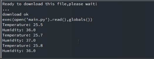
Similarly the OLED Display will also display the temperature & Humidity value on the screen. The data is refreshed and displayed after the interval of every two seconds.

Video Tutorial & Guide


13 Comments
Thank you, in my case work with:
in the main.py
“pin = Pin(28, Pin.IN, Pin.PULL_UP)”
Nice bit of code – with a few extensions to main.py (most now written and working when powered from a Pi4 via Thonny) and nearly ready to control a temperature and humidity controlled cabinet.
The question is, how can I get it to function independently from the Pi4?, i.e. just powered via USB or battery. I am very new to this game, and assumed that main.py would assure that everytihng would run fine in that situation.
Read Get started with MicroPython on Raspberry Pi Pico by Gareth Halfacree and Ben Everard starting on page 104.
i’m having problems with the main.py, “>>> %Run -c $EDITOR_CONTENT
I2C Address : 0X3C
I2C Configuration: I2C(0, freq=200000, scl=9, sda=8)
Traceback (most recent call last):
File “”, line 14, in
File “SSD1306.py”, line 110, in init
File “SSD1306.py”, line 31, in init
NameError: name ‘Height’ isn’t defined
Please Help?
trying to run on Pico – when I run main.py I get an error : ImportError: can’t import name SSD1306_I2C
hello , could you please help me to understand , why i see this error while run the “Main.py”
Traceback (most recent call last):
File “”, line 3, in
ImportError: no module named ‘ssd1306’
hi , i also see the similar error when try to run “main.py” error:
Traceback (most recent call last):
File “”, line 3, in
ImportError: no module named ‘ssd1306’
Clear the oled display in case it has junk on it.
Traceback (most recent call last):
File “”, line 26, in
AttributeError: ‘tuple’ object has no attribute ‘fill’
I’m honestly at a loss.
Did you try “SSD1306” instead of “ssd1306”?
It gave me an error for not using the correct capitalization.
how to round up the temp and hum with first digits
I had this, it was because I saved it as suggested, with UPPERCASE. I renamed SSD1306.py to ssd1306.py and it seemed to work.
I had this, it was because I saved it as suggested, with UPPERCASE. I renamed SSD1306.py to ssd1306.py and it seemed to work..
Thanks for the nice writeup.
I have a D091-12832-I2C oled display, so needed to change some settings.
Like: HEIGHT = 32 (and not 64)
And to this:
oled.text(“Temp: “,0,0)
oled.text(str(sensor.temperature),50,0)
oled.text(“*C”,90,0)
Now everything fits into the small screen.
I saved everything to the pico but does not start without my PC. So needs to figure out why.
All the best,
Nandor