

Overview
In this beginner’s guide, we’re going to play with a Micro SD Card Module and a microcontroller called Raspberry Pi Pico. With a language called MicroPython, we’ll teach our Pico to talk to the SD Card Module. This module is like a helper that lets Pico save and read data from a small SD card, just like the one you might use in your camera.
What’s cool is we’ll make a small device that can keep a record of things, like temperature or humidity, every second. This is called a Data Logger. This way, your Pico can store all kinds of data, like words, sounds, or pictures on the SD card. With this project, you can do more fun and useful things with your Raspberry Pi Pico.
Bill of Materials
For this tutorial, we recommend to buy the following list of components directly from given links.
| S.N. | Components Name | Quantity | Purchase Links |
|---|---|---|---|
| 1 | Raspberry Pi Pico | 1 | Amazon | AliExpress | SunFounder |
| 2 | SD Card Module | 1 | Amazon | AliExpress | SunFounder |
| 3 | SD Card 4-16 GB | 1 | Amazon | AliExpress | SunFounder |
| 4 | USB Card Reader | 1 | Amazon | AliExpress | SunFounder |
| 5 | Jumper Wires | 10 | Amazon | AliExpress | SunFounder |
SD Card Module/Adapter
The SD card module is especially useful for projects that require data logging. There are actually two ways to interface with micro SD cards – SPI mode and SDIO mode. Hobbyists like us prefer SPI Mode for interfacing as it’s easy compared to SDO mode which is very complex.

The operating voltage of micro SD Cards is 3.3 V. Therefore, we cannot SD Card directly with 5V logic. But the module has an onboard ultra-low dropout regulator that converts voltages from 3.3V – 6V down to ~3.3V. There is also a Logic Level converter IC 74LVC125A on the module which converts the interface logic from 3.3V-5V to 3.3V.
Micro SD Card Module Pinout
There are total of six pins (GND, VCC, MISO, MOSI, SCK, CS) on a SD-Card Adapter.

1. GND: Ground Pin
2. VCC: +5V power supply
3. MISO: SPI output
4. MOSI: SPI input
5. SCK: Accepts clock pulses for Data Synchronization
6. CS: Chip select signal pin to enable/disable line
Preparing the micro SD card

Before you insert the micro SD card into the module, you must properly format the card. You should format the SD card as FAT16 or FAT32.

To format the SD card, insert it into your computer. Go to My Computer and right-click on the SD card. A new window pops up. Select FAT32 as a Formatting option. Then press Start to initialize the formatting process

Now the SD Card is properly formatted and you can use the SD Card with SD Card Module to use in project applications.
Interfacing Micro SD Card Module with Raspberry Pi Pico
Now let us learn interfacing of SD Card Module with Raspberry Pi Pico to read & write data. Since the SD Card Module works on SPI Communication protocol, thus we need to connect it to SPI Pin of Raspberry Pi Pico Board.

Connect the SD Card Module to Raspberry Pi Pico as per the above Circuit Diagram. For Raspberry Pi Pico board, the SPI pins we can use are 2 (SCK), 4 (MISO), 3 (MOSI) and 1 (CS).

The connection between Pi Pico Board & SD Card Module is as follows.
| SD Card Pin | Raspberry Pi Pico |
| GND | GND |
| VCC | 3.3V |
| MISO | GP4 |
| MOSI | GP3 |
| SCK | GP2 |
| CS | GP1 |
SD Card MicroPython Library
For this project, we will require sdcard.py library. Here is a Micropython Library for interfacing Micro SD Card Module with a Raspberry Pi Pico.
|
1 2 3 4 5 6 7 8 9 10 11 12 13 14 15 16 17 18 19 20 21 22 23 24 25 26 27 28 29 30 31 32 33 34 35 36 37 38 39 40 41 42 43 44 45 46 47 48 49 50 51 52 53 54 55 56 57 58 59 60 61 62 63 64 65 66 67 68 69 70 71 72 73 74 75 76 77 78 79 80 81 82 83 84 85 86 87 88 89 90 91 92 93 94 95 96 97 98 99 100 101 102 103 104 105 106 107 108 109 110 111 112 113 114 115 116 117 118 119 120 121 122 123 124 125 126 127 128 129 130 131 132 133 134 135 136 137 138 139 140 141 142 143 144 145 146 147 148 149 150 151 152 153 154 155 156 157 158 159 160 161 162 163 164 165 166 167 168 169 170 171 172 173 174 175 176 177 178 179 180 181 182 183 184 185 186 187 188 189 190 191 192 193 194 195 196 197 198 199 200 201 202 203 204 205 206 207 208 209 210 211 212 213 214 215 216 217 218 219 220 221 222 223 224 225 226 227 228 229 230 231 232 233 234 235 236 237 238 239 240 241 242 243 244 245 246 247 248 249 250 251 252 253 254 255 256 257 258 259 260 261 262 263 264 265 266 267 268 269 270 271 272 273 274 275 276 277 278 279 280 281 282 283 284 285 286 287 288 289 290 291 292 293 294 295 296 297 298 299 300 301 |
""" MicroPython driver for SD cards using SPI bus. Origial: https://github.com/micropython/micropython/tree/master/drivers/sdcard RAW: https://raw.githubusercontent.com/micropython/micropython/master/drivers/sdcard/sdcard.py Requires an SPI bus and a CS pin. Provides readblocks and writeblocks methods so the device can be mounted as a filesystem. Example usage on pyboard: import pyb, sdcard, os sd = sdcard.SDCard(pyb.SPI(1), pyb.Pin.board.X5) pyb.mount(sd, '/sd2') os.listdir('/') Example usage on ESP8266: import machine, sdcard, os sd = sdcard.SDCard(machine.SPI(1), machine.Pin(15)) os.mount(sd, '/sd') os.listdir('/') """ from micropython import const import time _CMD_TIMEOUT = const(100) _R1_IDLE_STATE = const(1 << 0) # R1_ERASE_RESET = const(1 << 1) _R1_ILLEGAL_COMMAND = const(1 << 2) # R1_COM_CRC_ERROR = const(1 << 3) # R1_ERASE_SEQUENCE_ERROR = const(1 << 4) # R1_ADDRESS_ERROR = const(1 << 5) # R1_PARAMETER_ERROR = const(1 << 6) _TOKEN_CMD25 = const(0xFC) _TOKEN_STOP_TRAN = const(0xFD) _TOKEN_DATA = const(0xFE) class SDCard: def __init__(self, spi, cs, baudrate=1320000): self.spi = spi self.cs = cs self.cmdbuf = bytearray(6) self.dummybuf = bytearray(512) self.tokenbuf = bytearray(1) for i in range(512): self.dummybuf[i] = 0xFF self.dummybuf_memoryview = memoryview(self.dummybuf) # initialise the card self.init_card(baudrate) def init_spi(self, baudrate): try: master = self.spi.MASTER except AttributeError: # on ESP8266 self.spi.init(baudrate=baudrate, phase=0, polarity=0) else: # on pyboard self.spi.init(master, baudrate=baudrate, phase=0, polarity=0) def init_card(self, baudrate): # init CS pin self.cs.init(self.cs.OUT, value=1) # init SPI bus; use low data rate for initialisation self.init_spi(100000) # clock card at least 100 cycles with cs high for i in range(16): self.spi.write(b"\xff") # CMD0: init card; should return _R1_IDLE_STATE (allow 5 attempts) for _ in range(5): if self.cmd(0, 0, 0x95) == _R1_IDLE_STATE: break else: raise OSError("no SD card") # CMD8: determine card version r = self.cmd(8, 0x01AA, 0x87, 4) if r == _R1_IDLE_STATE: self.init_card_v2() elif r == (_R1_IDLE_STATE | _R1_ILLEGAL_COMMAND): self.init_card_v1() else: raise OSError("couldn't determine SD card version") # get the number of sectors # CMD9: response R2 (R1 byte + 16-byte block read) if self.cmd(9, 0, 0, 0, False) != 0: raise OSError("no response from SD card") csd = bytearray(16) self.readinto(csd) if csd[0] & 0xC0 == 0x40: # CSD version 2.0 self.sectors = ((csd[8] << 8 | csd[9]) + 1) * 1024 elif csd[0] & 0xC0 == 0x00: # CSD version 1.0 (old, <=2GB) c_size = (csd[6] & 0b11) << 10 | csd[7] << 2 | csd[8] >> 6 c_size_mult = (csd[9] & 0b11) << 1 | csd[10] >> 7 read_bl_len = csd[5] & 0b1111 capacity = (c_size + 1) * (2 ** (c_size_mult + 2)) * (2**read_bl_len) self.sectors = capacity // 512 else: raise OSError("SD card CSD format not supported") # print('sectors', self.sectors) # CMD16: set block length to 512 bytes if self.cmd(16, 512, 0) != 0: raise OSError("can't set 512 block size") # set to high data rate now that it's initialised self.init_spi(baudrate) def init_card_v1(self): for i in range(_CMD_TIMEOUT): self.cmd(55, 0, 0) if self.cmd(41, 0, 0) == 0: # SDSC card, uses byte addressing in read/write/erase commands self.cdv = 512 # print("[SDCard] v1 card") return raise OSError("timeout waiting for v1 card") def init_card_v2(self): for i in range(_CMD_TIMEOUT): time.sleep_ms(50) self.cmd(58, 0, 0, 4) self.cmd(55, 0, 0) if self.cmd(41, 0x40000000, 0) == 0: self.cmd(58, 0, 0, -4) # 4-byte response, negative means keep the first byte ocr = self.tokenbuf[0] # get first byte of response, which is OCR if not ocr & 0x40: # SDSC card, uses byte addressing in read/write/erase commands self.cdv = 512 else: # SDHC/SDXC card, uses block addressing in read/write/erase commands self.cdv = 1 # print("[SDCard] v2 card") return raise OSError("timeout waiting for v2 card") def cmd(self, cmd, arg, crc, final=0, release=True, skip1=False): self.cs(0) # create and send the command buf = self.cmdbuf buf[0] = 0x40 | cmd buf[1] = arg >> 24 buf[2] = arg >> 16 buf[3] = arg >> 8 buf[4] = arg buf[5] = crc self.spi.write(buf) if skip1: self.spi.readinto(self.tokenbuf, 0xFF) # wait for the response (response[7] == 0) for i in range(_CMD_TIMEOUT): self.spi.readinto(self.tokenbuf, 0xFF) response = self.tokenbuf[0] if not (response & 0x80): # this could be a big-endian integer that we are getting here # if final<0 then store the first byte to tokenbuf and discard the rest if final < 0: self.spi.readinto(self.tokenbuf, 0xFF) final = -1 - final for j in range(final): self.spi.write(b"\xff") if release: self.cs(1) self.spi.write(b"\xff") return response # timeout self.cs(1) self.spi.write(b"\xff") return -1 def readinto(self, buf): self.cs(0) # read until start byte (0xff) for i in range(_CMD_TIMEOUT): self.spi.readinto(self.tokenbuf, 0xFF) if self.tokenbuf[0] == _TOKEN_DATA: break time.sleep_ms(1) else: self.cs(1) raise OSError("timeout waiting for response") # read data mv = self.dummybuf_memoryview if len(buf) != len(mv): mv = mv[: len(buf)] self.spi.write_readinto(mv, buf) # read checksum self.spi.write(b"\xff") self.spi.write(b"\xff") self.cs(1) self.spi.write(b"\xff") def write(self, token, buf): self.cs(0) # send: start of block, data, checksum self.spi.read(1, token) self.spi.write(buf) self.spi.write(b"\xff") self.spi.write(b"\xff") # check the response if (self.spi.read(1, 0xFF)[0] & 0x1F) != 0x05: self.cs(1) self.spi.write(b"\xff") return # wait for write to finish while self.spi.read(1, 0xFF)[0] == 0: pass self.cs(1) self.spi.write(b"\xff") def write_token(self, token): self.cs(0) self.spi.read(1, token) self.spi.write(b"\xff") # wait for write to finish while self.spi.read(1, 0xFF)[0] == 0x00: pass self.cs(1) self.spi.write(b"\xff") def readblocks(self, block_num, buf): nblocks = len(buf) // 512 assert nblocks and not len(buf) % 512, "Buffer length is invalid" if nblocks == 1: # CMD17: set read address for single block if self.cmd(17, block_num * self.cdv, 0, release=False) != 0: # release the card self.cs(1) raise OSError(5) # EIO # receive the data and release card self.readinto(buf) else: # CMD18: set read address for multiple blocks if self.cmd(18, block_num * self.cdv, 0, release=False) != 0: # release the card self.cs(1) raise OSError(5) # EIO offset = 0 mv = memoryview(buf) while nblocks: # receive the data and release card self.readinto(mv[offset : offset + 512]) offset += 512 nblocks -= 1 if self.cmd(12, 0, 0xFF, skip1=True): raise OSError(5) # EIO def writeblocks(self, block_num, buf): nblocks, err = divmod(len(buf), 512) assert nblocks and not err, "Buffer length is invalid" if nblocks == 1: # CMD24: set write address for single block if self.cmd(24, block_num * self.cdv, 0) != 0: raise OSError(5) # EIO # send the data self.write(_TOKEN_DATA, buf) else: # CMD25: set write address for first block if self.cmd(25, block_num * self.cdv, 0) != 0: raise OSError(5) # EIO # send the data offset = 0 mv = memoryview(buf) while nblocks: self.write(_TOKEN_CMD25, mv[offset : offset + 512]) offset += 512 nblocks -= 1 self.write_token(_TOKEN_STOP_TRAN) def ioctl(self, op, arg): if op == 4: # get number of blocks return self.sectors if op == 5: # get block size in bytes return 512 |
Copy this code to Thonny IDE and save it to the Raspberry Pi Pico with a name “sdcard.py“.
MicroPython Sketch: Read/Write on a File
The following sketch can be used to read/write data on a .txt file. Open a new tab in Thonny IDE and copy the following MicroPython Code. Save the file as main.py.
|
1 2 3 4 5 6 7 8 9 10 11 12 13 14 15 16 17 18 19 20 21 22 23 24 25 26 27 28 29 30 31 32 33 34 |
import machine import sdcard import uos # Assign chip select (CS) pin (and start it high) cs = machine.Pin(1, machine.Pin.OUT) # Intialize SPI peripheral (start with 1 MHz) spi = machine.SPI(0, baudrate=1000000, polarity=0, phase=0, bits=8, firstbit=machine.SPI.MSB, sck=machine.Pin(2), mosi=machine.Pin(3), miso=machine.Pin(4)) # Initialize SD card sd = sdcard.SDCard(spi, cs) # Mount filesystem vfs = uos.VfsFat(sd) uos.mount(vfs, "/sd") # Create a file and write something to it with open("/sd/test01.txt", "w") as file: file.write("Hello, SD World!\r\n") file.write("This is a test\r\n") # Open the file we just created and read from it with open("/sd/test01.txt", "r") as file: data = file.read() print(data) |
This sketch will read and write data on a .txt file which will be saved on the microSD card.
Code Explanation
|
1 2 3 |
import machine import sdcard import uos |
The first three lines of the code import the modules that we will be using. The machine module gives us access to basic hardware components on the board such as pins and the SPI. The sdcard module contains classes for interacting with SD cards, and the uos module provides functions for file and directory handling.
|
1 |
cs = machine.Pin(1, machine.Pin.OUT) |
In this line, a GPIO pin (in this case, pin number 1) is being set up as an output pin. This output pin will be used as the Chip Select (CS) for the SPI interface.
|
1 2 3 4 5 6 7 8 9 |
spi = machine.SPI(0, baudrate=1000000, polarity=0, phase=0, bits=8, firstbit=machine.SPI.MSB, sck=machine.Pin(2), mosi=machine.Pin(3), miso=machine.Pin(4)) |
Here, we are initializing the SPI (Serial Peripheral Interface) with the desired settings. We’re using the SPI bus number 0 with a baud rate of 1 MHz. The polarity and phase are set to 0 which determines the idle state of the clock and the edge of the clock pulse on which data is captured, respectively. The data word size is 8 bits and the first bit sent/received is the most significant bit (MSB). The pins for the clock (sck), master out slave in (mosi), and master in slave out (miso) are also being set in this line.
|
1 2 3 |
sd = sdcard.SDCard(spi, cs) vfs = uos.VfsFat(sd) uos.mount(vfs, "/sd") |
These lines initialize the SD card over the SPI and mount it to the file system. First, the SD card is initialized using the SPI bus and the chip select pin. Then, a virtual file system (VFS) is created with a FAT file system on the SD card. Finally, the VFS is mounted at the “/sd” directory.
|
1 2 3 |
with open("/sd/test01.txt", "w") as file: file.write("Hello, SD World!\r\n") file.write("This is a test\r\n") |
Here, a file named “test01.txt” is opened in write mode in the “/sd” directory, which corresponds to the root directory of our SD card. If the file does not exist, it is created. Then, two lines of text are written to the file.
|
1 2 3 |
with open("/sd/test01.txt", "r") as file: data = file.read() print(data) |
In the last part, the same file is opened again, but this time in read mode. The contents of the file are read into the variable data and then printed out.
Demonstration & Results
Run the main.py code and you will see the following messages on Thonny Shell.
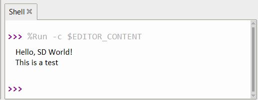
This message indicates the SD Card is working fine and a .txt file has been created with some written text.
In order to view the file and text, insert the SD Card into card reader and plug it into your computer.

You will see a file has been created. Open the .txt file.

This is how we write files in a SD Card using Raspberry Pi Pico with MicroPython Code.


