

Overview
In this project, we will build a portable pedometer using an ESP32 microcontroller and the BMI160 Accelerometer Gyroscope Module from Bosch. In a previous article (BMI160 Guide), we discussed the BMI160 module’s features, capabilities, and applications—comparing it with the MPU6050 along the way.
This project focuses on the practical application of the BMI160’s built‑in step-counting algorithm. Our design features an OLED display that provides real‑time feedback on your step count, while the unit is powered by a 3.7V Lithium‑ion battery. The device also includes a boost converter, a slide switch for power management, and a push button that resets the step counter when pressed. Compact enough to fit in your pocket, this pedometer records your walking steps accurately.
In addition to displaying the step count on the OLED, the ESP32 uses Bluetooth Low Energy (BLE) to transmit data to your mobile device via the nRF Connect app.
Bill of Materials
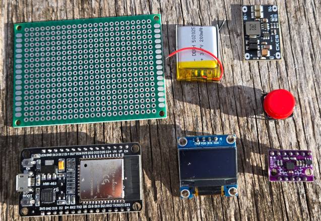
To build an ESP32 Pedometer for steps counting, we need the following components.
| S.N. | Components Name | Quantity | Purchase Link |
|---|---|---|---|
| 1 | ESP32 Board | 1 | Amazon | AliExpress |
| 2 | BMI160 Accelerometer Gyroscope | 1 | Amazon | AliExpress |
| 3 | 0.96" OLED Display | 1 | Amazon | AliExpress |
| Push Button Switch | 1 | Amazon | AliExpress | |
| Resistor 1K | 1 | Amazon | AliExpress | |
| 3.7V Lithium-ion Battery | 1 | Amazon | AliExpress | |
| Boost Converter Module | 1 | Amazon | AliExpress | |
| Slide Switch | 1 | Amazon | AliExpress |
BMI160 3 Axis Accelerometer & Gyroscope
The BMI160 is a high-performance, small, and ultra-low-power 16-bit Inertial Measurement Unit (IMU) that combines a 3-axis accelerometer and a 3-axis gyroscope in a single package.
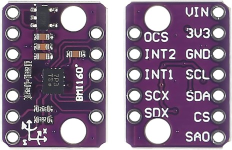
It is designed to deliver accurate and reliable motion sensing for a wide range of applications, such as augmented reality, indoor navigation, wearable devices, and gaming. The sensor offers advanced features like motion detection, step counting, and gesture recognition, making it versatile for modern technology needs.
The BMI160 supports both I2C and SPI interfaces for communication, making it compatible with a variety of microcontrollers and processors. Refer to Bosch BMI160 Datasheet for more information.
Steps Counter Algorithm in BMI160 Module
The BMI160 has a dedicated, on‐chip step counter that sets it apart from many older sensors like the MPU6050. Here’s how and why it can calculate steps:
-
Dedicated Hardware Algorithm:
Unlike the MPU6050—which only provides raw accelerometer and gyroscope data and requires you to implement your own step detection algorithm—the BMI160 integrates a digital signal processing block specifically for step counting. This hardware module continuously filters and analyzes the acceleration data to detect step-like movements. -
Threshold and Debounce Logic:
The sensor’s internal algorithm monitors the periodic changes in acceleration that occur during walking. It applies threshold detection (and adjustable sensitivity settings) to determine when a valid step occurs. It also incorporates debounce logic, ensuring that only distinct, well-separated peaks (steps) are counted.
-
Inbuilt Registers:
When a step is detected, the BMI160 automatically increments an internal step counter. This counter is stored in dedicated registers (typically found at addresses 0x78 and 0x79), which can be read directly via I²C or SPI. -
Simplified Integration:
Because the step counting is handled internally, designers can quickly implement a pedometer by simply reading the step count register—no complex filtering or peak detection algorithms need to be implemented in your firmware.
Building a Pedometer using BMI160 & ESP32
First, let’s design the ESP32 Pedometer hardware that can count steps and display on the OLED screen.
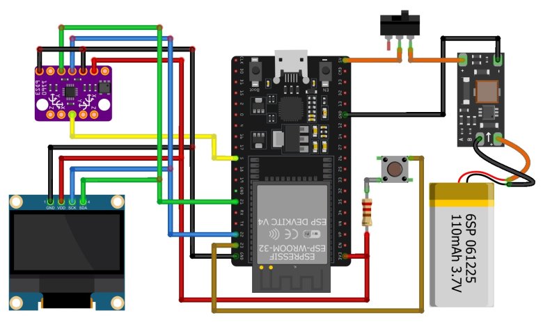
In this schematic, the ESP32 is the main board which supports Wi-Fi and Bluetooth. The BMI160 sensor measures acceleration and gyroscope data. The OLED display shows the step count.
Both the BMI160 and OLED connect to the same I2C pins on the ESP32. The BMI160’s interrupt pin goes to GPIO 5, and a push button on GPIO 23 resets the steps.
A 3.7 V lithium-ion battery powers the system. A boost converter steps the battery voltage up to 5 V, which goes to the 5 V pin on the ESP32. You must set the boost converter to 5 V before using it. By default, it may be at 12 V.
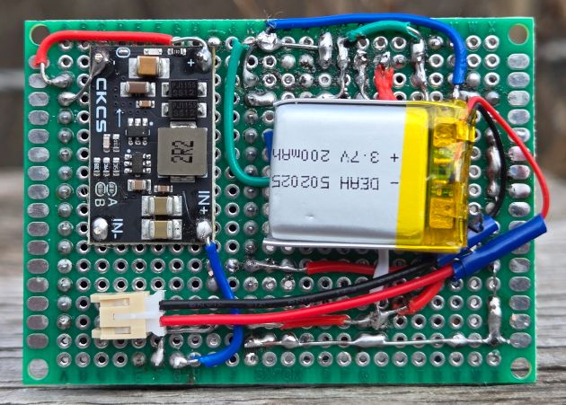
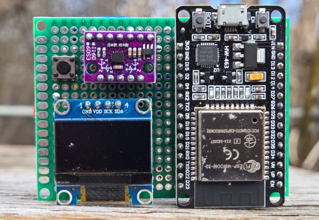
Everything is assembled on a zero PCB board. The ESP32, OLED, and BMI160 use female header pins for easy placement. A slide switch turns the circuit on or off.
Source Code/Program for ESP32 Pedometer (Steps Counter)
After doing the hardware assembly, we can write a C++ Code for ESP32 BMI160 Steps Counter.
This following code uses the BMI160’s built-in step counting algorithm, which filters and analyzes accelerometer data to detect valid footstep patterns. Each time the sensor identifies a step, it increments an internal counter. The code then reads that counter value and displays it on the OLED, as well as prints it to the Serial Monitor. A push button on pin 23 resets the count, letting you start fresh at any time.
Add the following libraries to the Arduino library folder, before working on the coding and debugging part.
- BMI160 Library: https://github.com/hanyazou/BMI160-Arduino
- Adafruit GFX Library: https://github.com/adafruit/Adafruit-GFX-Library
- Adafruit SSD1306 Library: https://github.com/adafruit/Adafruit_SSD1306
Copy the following code and paste it to the editor window.
|
1 2 3 4 5 6 7 8 9 10 11 12 13 14 15 16 17 18 19 20 21 22 23 24 25 26 27 28 29 30 31 32 33 34 35 36 37 38 39 40 41 42 43 44 45 46 47 48 49 50 51 52 53 54 55 56 57 58 59 60 61 62 63 64 65 66 67 68 69 70 71 72 73 74 75 76 77 78 79 80 81 82 83 84 85 86 87 88 89 90 91 92 93 94 95 96 97 98 99 100 101 102 103 104 105 106 107 108 109 110 111 112 113 114 115 116 117 118 119 120 121 122 123 124 125 126 127 128 129 130 131 |
#include <Wire.h> #include <BMI160Gen.h> #include <Adafruit_GFX.h> #include <Adafruit_SSD1306.h> // OLED display definitions for a 0.96" (128x64) display #define SCREEN_WIDTH 128 #define SCREEN_HEIGHT 64 #define OLED_RESET -1 // No dedicated reset pin Adafruit_SSD1306 display(SCREEN_WIDTH, SCREEN_HEIGHT, &Wire, OLED_RESET); // Sensor parameters: const int BMI160_I2C_ADDRESS = 0x68; // BMI160 I2C Address const int INTERRUPT_PIN = 5; // Digital pin used for sensor interrupt // Reset button pin: const int RESET_BUTTON_PIN = 23; // Reset button connected to GP23 // Optional: Interrupt callback (for future embellishments) void stepInterrupt() { // This callback is triggered on an interrupt (e.g., double-tap). // The built-in step counter works independently. } void setup() { Serial.begin(115200); while (!Serial) { } // Wait for Serial Monitor // Set the reset button pin with internal pulldown so that when not pressed, it is LOW. pinMode(RESET_BUTTON_PIN, INPUT_PULLDOWN); // Initialize the OLED display if (!display.begin(SSD1306_SWITCHCAPVCC, 0x3C)) { // Typical OLED I2C address is 0x3C Serial.println(F("SSD1306 allocation failed")); while (1); } display.clearDisplay(); display.display(); // Initialize BMI160 sensor in I2C mode if (!BMI160.begin(BMI160GenClass::I2C_MODE, BMI160_I2C_ADDRESS, INTERRUPT_PIN)) { Serial.println("BMI160 initialization failed!"); while (1); } BMI160.attachInterrupt(stepInterrupt); // --- Auto-Calibration for Improved Accuracy --- // (Ensure the sensor is stationary during calibration) BMI160.autoCalibrateGyroOffset(); BMI160.autoCalibrateXAccelOffset(0); // X-axis to 0g BMI160.autoCalibrateYAccelOffset(0); // Y-axis to 0g BMI160.autoCalibrateZAccelOffset(1); // Z-axis to +1g (gravity) // Set accelerometer range to 2g (for higher sensitivity in step detection) BMI160.setFullScaleAccelRange(BMI160_ACCEL_RANGE_2G); // --- Configure the Built-In Step Counter --- // Options: BMI160_STEP_MODE_NORMAL, SENSITIVE, or ROBUST BMI160.setStepDetectionMode(BMI160_STEP_MODE_NORMAL); BMI160.setStepCountEnabled(true); BMI160.resetStepCount(); // Initial OLED decoration display.clearDisplay(); // Draw border display.drawRect(0, 0, SCREEN_WIDTH, SCREEN_HEIGHT, SSD1306_WHITE); // Header text in small font display.setTextSize(1); display.setTextColor(SSD1306_WHITE); String header = "BMI160 STEP COUNTER"; int headerWidth = header.length() * 6; // Approximate width at size 1 int headerX = (SCREEN_WIDTH - headerWidth) / 2; display.setCursor(headerX, 3); display.println(header); // Draw a horizontal separator display.drawLine(0, 15, SCREEN_WIDTH, 15, SSD1306_WHITE); display.display(); delay(1000); } void loop() { // Check the reset button. When pressed, reset the step counter. if(digitalRead(RESET_BUTTON_PIN) == HIGH) { BMI160.resetStepCount(); Serial.println("Counter reset!"); delay(300); // simple debounce delay } // Read the step count from the BMI160 sensor uint16_t currentSteps = BMI160.getStepCount(); // Print the step count to Serial Monitor Serial.print("Steps: "); Serial.println(currentSteps); // Clear the display before redrawing display.clearDisplay(); // Draw a border around the screen display.drawRect(0, 0, SCREEN_WIDTH, SCREEN_HEIGHT, SSD1306_WHITE); // --- Header Section --- display.setTextSize(1); display.setTextColor(SSD1306_WHITE); String header = "BMI160 STEP COUNTER"; int headerWidth = header.length() * 6; int headerX = (SCREEN_WIDTH - headerWidth) / 2; display.setCursor(headerX, 3); display.println(header); display.drawLine(0, 15, SCREEN_WIDTH, 15, SSD1306_WHITE); // --- Step Count Section --- String stepText = String(currentSteps); display.setTextSize(3); int stepWidth = stepText.length() * 18; // Approximate width at size 3 int stepX = (SCREEN_WIDTH - stepWidth) / 2; display.setCursor(stepX, 25); display.println(stepText); // --- Footer Section --- display.setTextSize(1); String footer = "Steps"; int footerWidth = footer.length() * 6; int footerX = (SCREEN_WIDTH - footerWidth) / 2; display.setCursor(footerX, 55); display.println(footer); display.display(); delay(200); // Refresh display every 200 ms } |
To upload the code, choose the ESP32 Board and the COM port. Then hit the upload button to upload the code.
Testing the Pedometer Steps Counts
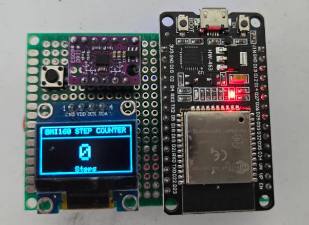
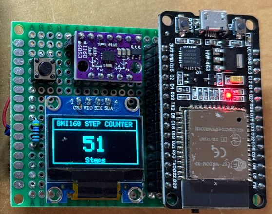
After uploading the code, the ESP32 Steps Counter project is ready for testing. First slide the switch to power it on. The OLED display should show zero steps at the center.
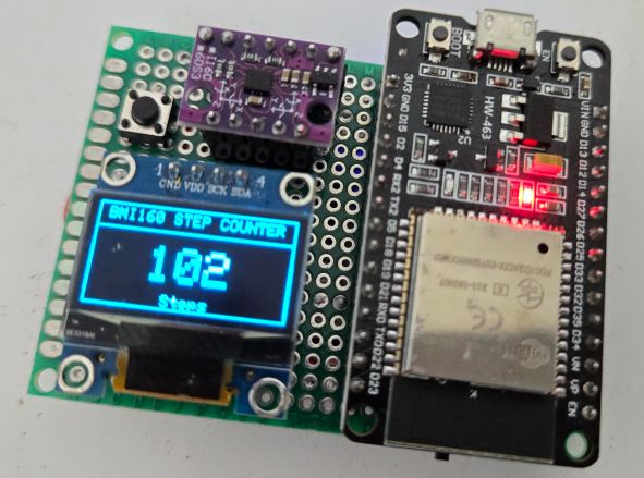
Place the device in your pocket and walk around for a minute or two, then check the displayed step count.
Compare it with your own manual count to see if it’s accurate.
You can also shake the sensor by hand to see if it adds any extra steps. In many cases, you’ll notice a few steps get recorded even when you’re just shaking it, but it’s generally far more accurate while walking.
If you need to start over, press the reset button to bring the count back to zero.
Sending Pedometer (Steps Counts) Data over ESP32 BLE
To enhance this project with wireless functionality, we took advantage of the ESP32’s built-in Bluetooth Low Energy (BLE) feature. We modified the original code by adding the necessary BLE libraries and creating a dedicated service and characteristic for the step count data. With these changes, the pedometer now broadcasts the current step count to any BLE-enabled device, such as a smartphone or tablet.
Copy the following code and upload it to the ESP32 Board.
|
1 2 3 4 5 6 7 8 9 10 11 12 13 14 15 16 17 18 19 20 21 22 23 24 25 26 27 28 29 30 31 32 33 34 35 36 37 38 39 40 41 42 43 44 45 46 47 48 49 50 51 52 53 54 55 56 57 58 59 60 61 62 63 64 65 66 67 68 69 70 71 72 73 74 75 76 77 78 79 80 81 82 83 84 85 86 87 88 89 90 91 92 93 94 95 96 97 98 99 100 101 102 103 104 105 106 107 108 109 110 111 112 113 114 115 116 117 118 119 120 121 122 123 124 125 126 127 128 129 130 131 132 133 134 135 136 137 138 139 140 141 142 143 144 145 146 147 148 149 150 151 152 153 154 155 156 157 158 159 160 161 162 163 164 165 166 167 168 169 170 171 172 173 174 |
#include <Wire.h> #include <BMI160Gen.h> #include <Adafruit_GFX.h> #include <Adafruit_SSD1306.h> #include <BLEDevice.h> #include <BLEUtils.h> #include <BLEServer.h> // OLED display definitions for a 0.96" (128x64) display #define SCREEN_WIDTH 128 #define SCREEN_HEIGHT 64 #define OLED_RESET -1 // No dedicated reset pin Adafruit_SSD1306 display(SCREEN_WIDTH, SCREEN_HEIGHT, &Wire, OLED_RESET); // Sensor parameters: const int BMI160_I2C_ADDRESS = 0x68; // BMI160 I2C Address const int INTERRUPT_PIN = 5; // Digital pin used for sensor interrupt // Reset button pin (connected to GP23) const int RESET_BUTTON_PIN = 23; // When pressed, this pin is pulled HIGH // BLE service and characteristic UUIDs (custom values) #define SERVICE_UUID "4fafc201-1fb5-459e-8fcc-c5c9c331914b" #define CHARACTERISTIC_UUID "beb5483e-36e1-4688-b7f5-ea07361b26a8" // BLE characteristic pointer and connection flag BLECharacteristic *pCharacteristic; bool deviceConnected = false; // BLE server callbacks to print connection messages class MyServerCallbacks: public BLEServerCallbacks { void onConnect(BLEServer* pServer) { deviceConnected = true; Serial.println("BLE client connected"); } void onDisconnect(BLEServer* pServer) { deviceConnected = false; Serial.println("BLE client disconnected"); } }; // Optional: Interrupt callback (for future embellishments) void stepInterrupt() { // This callback is triggered on a sensor interrupt. // The built-in step counter operates independently. } void setup() { Serial.begin(115200); while (!Serial) { } // Wait for Serial Monitor // Configure the reset button pin with internal pull-down pinMode(RESET_BUTTON_PIN, INPUT_PULLDOWN); // Initialize the OLED display if (!display.begin(SSD1306_SWITCHCAPVCC, 0x3C)) { // OLED I2C address is typically 0x3C Serial.println(F("SSD1306 allocation failed")); while (1); } display.clearDisplay(); display.display(); // Initialize BMI160 sensor in I2C mode if (!BMI160.begin(BMI160GenClass::I2C_MODE, BMI160_I2C_ADDRESS, INTERRUPT_PIN)) { Serial.println("BMI160 initialization failed!"); while (1); } BMI160.attachInterrupt(stepInterrupt); // --- Auto-Calibration for Improved Accuracy --- // Ensure the sensor is stationary during calibration! BMI160.autoCalibrateGyroOffset(); BMI160.autoCalibrateXAccelOffset(0); // Calibrate X-axis to 0g BMI160.autoCalibrateYAccelOffset(0); // Calibrate Y-axis to 0g BMI160.autoCalibrateZAccelOffset(1); // Calibrate Z-axis to +1g (gravity) // Set accelerometer range to 2g for higher sensitivity in step detection BMI160.setFullScaleAccelRange(BMI160_ACCEL_RANGE_2G); // --- Configure the Built-In Step Counter --- // Options: BMI160_STEP_MODE_NORMAL, SENSITIVE, or ROBUST BMI160.setStepDetectionMode(BMI160_STEP_MODE_NORMAL); BMI160.setStepCountEnabled(true); BMI160.resetStepCount(); // --- Initialize BLE --- BLEDevice::init("ESP32_StepCounter"); BLEServer *pServer = BLEDevice::createServer(); pServer->setCallbacks(new MyServerCallbacks()); BLEService *pService = pServer->createService(SERVICE_UUID); pCharacteristic = pService->createCharacteristic( CHARACTERISTIC_UUID, BLECharacteristic::PROPERTY_READ | BLECharacteristic::PROPERTY_NOTIFY ); pCharacteristic->setValue("0"); pService->start(); BLEAdvertising *pAdvertising = pServer->getAdvertising(); pAdvertising->start(); Serial.println("BLE advertising started"); // Initial OLED decoration display.clearDisplay(); display.drawRect(0, 0, SCREEN_WIDTH, SCREEN_HEIGHT, SSD1306_WHITE); display.setTextSize(1); display.setTextColor(SSD1306_WHITE); String header = "BMI160 STEP COUNTER"; int headerWidth = header.length() * 6; // Approximate width at size 1 int headerX = (SCREEN_WIDTH - headerWidth) / 2; display.setCursor(headerX, 3); display.println(header); display.drawLine(0, 15, SCREEN_WIDTH, 15, SSD1306_WHITE); display.display(); delay(1000); } void loop() { // Check if the reset button is pressed (reads HIGH when pressed) if (digitalRead(RESET_BUTTON_PIN) == HIGH) { BMI160.resetStepCount(); Serial.println("Counter reset!"); delay(300); // Simple debounce delay } // Read the step count from the BMI160 sensor uint16_t currentSteps = BMI160.getStepCount(); // Print the current step count to Serial Monitor Serial.print("Steps: "); Serial.println(currentSteps); // Update OLED display display.clearDisplay(); display.drawRect(0, 0, SCREEN_WIDTH, SCREEN_HEIGHT, SSD1306_WHITE); // --- Header Section --- display.setTextSize(1); display.setTextColor(SSD1306_WHITE); String header = "BMI160 STEP COUNTER"; int headerWidth = header.length() * 6; int headerX = (SCREEN_WIDTH - headerWidth) / 2; display.setCursor(headerX, 3); display.println(header); display.drawLine(0, 15, SCREEN_WIDTH, 15, SSD1306_WHITE); // --- Step Count Section --- String stepText = String(currentSteps); display.setTextSize(3); int stepWidth = stepText.length() * 18; // Approximate width at size 3 int stepX = (SCREEN_WIDTH - stepWidth) / 2; display.setCursor(stepX, 25); display.println(stepText); // --- Footer Section --- display.setTextSize(1); String footer = "Steps"; int footerWidth = footer.length() * 6; int footerX = (SCREEN_WIDTH - footerWidth) / 2; display.setCursor(footerX, 55); display.println(footer); display.display(); // Update BLE characteristic and send notification if connected String stepsStr = String(currentSteps); pCharacteristic->setValue(stepsStr.c_str()); pCharacteristic->notify(); // Print BLE notification info to Serial Monitor if connected if (deviceConnected) { Serial.println("BLE notification sent"); } delay(200); // Refresh display and BLE update every 200 ms } |
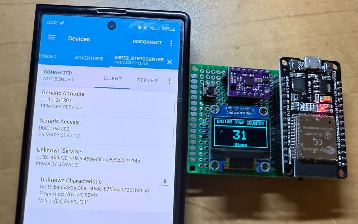
To test the BLE functionality, first install the nRF Connect app on your phone (available for both Android and iOS). Turn on your phone’s Bluetooth and GPS, then open the nRF Connect app to begin scanning.
You should see a device named “ESP32_StepCounter” appear in the list. Tap it to connect, and locate the characteristic UUID specified in the code. When you tap the download button (in the nRF Connect interface), the current step count will appear.

At first, it may show 0 steps, but if you walk around, the number will update (for example, to 31). Each time you want to see the latest value, tap the download button again to refresh.
This confirms that the ESP32 is broadcasting the step count data over Bluetooth Low Energy. This is how you an build a ESP32 Steps Counter using BMI160. You can make a project called Flight Black-Box Motion Recorder using ESP32 and BMI160.
Video Tutorial & Guide


2 Comments
thanks a lot.
Hello, I watch your YouTube with interest. I am a beginner with the ESP32 and purchased a FreeNove ESP32-S3 WROOM development board thinking it would make building project easier. I have to define the SDA and SCL pins in my program, but I notice you have not done this in your code. Can you tell me why not? In order to get your program to work with my ESP32S3, is it possible for you to tell me who I need to modify your code? Thank you for all your work. I have you can find a few minutes to answer my question. It is so frustrating to be so close (I think) and yet so far!
Lawrence