

Solder (or brazing filler metal) serves as a filler metal in the process of brazing. In contemporary manufacturing, welding technology functions as an essential method for uniting electronic components, metal parts, and precise devices. The solder melting temperature has a direct impact on the quality, effectiveness, and suitable situations for welding.
From conventional tin-lead alloys to eco-friendly lead-free options and specialized high-melting-point solders or low-temperature solders, the differences in melting single temperature illustrate a significant interaction among material science, technological needs, and environmental policies.
The Solder Material System
Conventional solder compositions are lead-based solders mainly consisting of a lead-tin ( eutectic Sn-Pb solder) alloy, recognized for its stable composition and comparatively low melting point (with the eutectic 63Sn-37Pb solder melting at 183 degrees Celsius). It features outstanding welding and processing capabilities and is economical, resulting in its extensive application.
Nonetheless, with the rise of global environmental awareness, nations are progressively seeking eco-conscious electronic production and alternative Pb-free solder. This change has triggered the wide range of creation and use of solders without lead. These new solders must not only fulfill the fundamental criteria of traditional solders but also have extra physical properties:
- They must not bring in any new pollutants moving forward.
- Their melting temperature ought to be similar to that of the 63Sn-37Pb eutectic solder.
- They need to be compatible with the current soldering station. They ought to demonstrate favorable processing traits.
In many countries, the creation and application of lead-free solder mainly emphasize Sn-based solders. The main lead-free solder alloys consist mainly of binary alloy systems such as Sn-Ag, Sn-Au, Sn-Cu, Sn-Bi solders, Sn-Zn, and Sn-In, as well as ternary systems such as Sn-Ag-Cu and Sn-Ag-Bi.
Table 9-35 details the performance traits of lead-free solders that could possibly serve as a solid solution for conventional lead-tin solders. Of these, the Sn-Ag-Cu system is now the most commonly utilized lead-free solder.
The Scientific Essence of Melting Point for Lead-Free Solder
The melting temperature of solder wire refers to the range of operating temperatures at which a material transitions from a solid to a liquid solder. For pure metals, this melting point is a fixed value. However, solder wire is typically an alloy, and its melting process generally occurs over a temperature range, from the solidus line to the liquidus line.
For example, a 60% tin/40% lead-based solder begins to soften at 183°C (solidus) and becomes fully liquid solder at 190°C (liquidus). This characteristic directly influences the control window in the soldering process: if the temperature is too low, it may lead to weak joints, while excessively high-melting-point solders can damage electrical components.
Eutectic Alloys
Such as the 63% tin/37% lead composition, where the solidus and liquidus lines coincide at 183°C, allowing for instantaneous melting, which is ideal for precision soldering iron.
Non-Eutectic Alloys:
These have a melting range and require the temperature to be maintained above the liquidus line to achieve adequate wetting.
Classification of Rohs Solder and Typical Melting Temperatures
The composition design of solder is directly related to its melting temperature. Below are the classifications and characteristics of mainstream soldiers:
Tin-Lead Solder (Traditional Mainstream)
- 63/37 Tin-Lead Solder (Eutectic Sn-Pb solder): Melting point of 183°C, solidifies quickly, offers high welding strength, and was once considered the “gold standard” in the electronics industry.
- 60/40 Tin-Lead Solder: Melting range of 183-190°C, with a wider melting window suitable for the flexibility required in manual soldering iron.
However, due to the toxicity of lead, this type of solder was restricted by the RoHS Directive issued in 2006.
Lead-Free Solder (Eco-Friendly Alternatives)
- SAC Series (e.g., SAC305): Zn Tin-Silver-Zinc alloys for soldering with a melting point of 217-220°C, offering excellent mechanical properties, though high soldering temperatures may cause PCB warping.
- Sn-Cu Alloy (e.g., Sn99.3Cu0.7): Melting point of 227°C, cost-effective and suitable for wave step soldering, though it has poorer wettability.
- Sn-Bi solder (e.g., Sn42Bi58): The Melting point of 138°C, ideal for heat-sensitive components like LEDs due to its low-temperature characteristic, but it exhibits higher brittleness for heat-sensitive components.
Specialty Solders
- High-Temperature Solder: Such as Pb-Ag alloy composition with a melting point of 300-400°C, used in aerospace engines or electrical equipment.
- Low-Temperature Solder: Such as In-48Sn solder with a melting point of 118°C, used in optoelectronic packaging or biological circuits to avoid thermal damage.
The Impact of Melting Temperature on the Welding Process
The melting temperature of solder candidates is one of the most critical parameters in the welding process, directly impacting the welding quality, efficiency, equipment selection, and ultimately the reliability of the final product. From the microscopic formation of intermetallic compounds to the macroscopic control of process windows, the melting temperature is integral throughout the entire welding procedure.
Benchmark for Process Parameter Settings
In the design of temperature profiles, it is essential to optimize the temperature curves of welding equipment (such as reflow soldering ovens and wave solder melting machines) based on the melting point solder. For example, in the preheat zone, the temperature should be gradually increased to slightly below the solidus temperature of the solder candidates to avoid thermal shock that may cause deformation of components or PCB.
In the activation zone, where the solder flux activates, it is crucial to ensure the temperature does not exceed the liquidus temperature of the solder flux to prevent premature melting. In the reflow zone, the temperature should rise 20-50°C above the liquidus line (e.g., SAC305 should reach 240-250°C) to ensure the solder adequately wets the pads. In the cooling zone, rapid cooling helps refine the grain hierarchy of solder joints, enhancing mechanical strength.
Wettability and Solder Joint Formation
Once the solder is fully melted, it must achieve good wettability on the substrate surface (such as copper or nickel), indicated by a contact angle of less than 90 degrees. If the temperature is insufficient, the solder exhibits poor fluidity, resulting in inadequate wetting and forming defective or “ball-shaped” joints (cold soldering). Conversely, if the temperature is too high, it accelerates metal oxidation, generating excessive dross (such as SnO), which diminishes the electrical hierarchy of solder joints.
Risks Associated with Thermally Sensitive Components
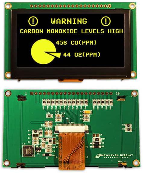
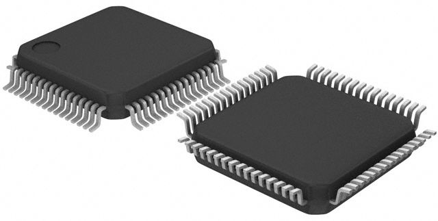
LEDs, plastic connectors, and IC chips typically have a temperature tolerance below 200°C. When using high-temperature solder, such as SAC305 with a melting point of 217°C, the soldering process may exceed the components’ thermal limits, potentially resulting in deformation or functional failure.
PCB Layering and Warping
The glass transition temperature (Tg) is approximately 130-180°C. If the soldering temperature exceeds Tg, such as in lead-free processes reaching up to 250°C, the PCB is prone to delamination or warping.
Weld Formation
Excessively high or low temperatures can adversely affect the weld’s quality. High-melting-point solders are incorrectly used the flowability of the molten metal increases, potentially leading to defects such as overly wide welds, uneven surfaces, and undercutting. Conversely, if the temperature is too low, the reduced flowability of the molten metal may result in incomplete penetration, narrow welds, and insufficient weld height.
Requirements for Solder Performance in Integrated Circuit
To meet the requirements of the brazing process and the performance of brazed joints, it is a solid solution that the solder used as a connecting material must generally satisfy the following basic criteria. You can also find such solder in Unikeyic.
- It should have an appropriate melting point solder, which must be lower than the melting temperature of the base material being welded.
- It should exhibit excellent adequate wetting ability and spreading characteristics with the base material, allowing for proper dissolution and diffusion with the metal of the base material.
- The welding interface should possess a certain mechanical strength and maintain stable physical and chemical properties.
- It should be moderately priced, with a low content of rare and precious metals.
The solder melting temperature is not merely a physical parameter; it serves as the “conductor’s baton” for welding processes. From microscopic interfacial reactions to the macroscopic selection of equipment, temperature control plays a primary role through the choice of solder. In the future, with the integration of new materials and intelligent technologies, welding processes will become more efficient and precise, yet the choice of solder is increasingly abundant, and the optimization of melting temperature will remain an enduring subject of research in this field.


