

Overview
This is the Getting Started guide with NuMaker UNO Board from the Nuvoton NuMicro NUC131 series of Microcontroller family. The NuMicro® NuMaker UNO Evaluation Board is Arduino-compatible hardware using a NuMicro® microcontroller (MCU) as the MCU. Its function can be extended with Arduino add-ons. With the Arduino IDE, users can develop their applications and leverage a large number of open-source samples.

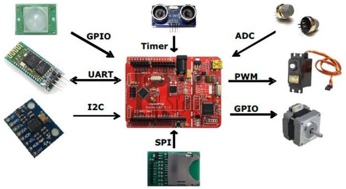
Using this board the users can develop and verify the application program easily with ADC, PWM, I²C, SPI, UART and other peripheral functions, the user can set different functions on the NuMaker UNO development kit, or increase the peripheral functions according to the user needs on the development kit.
The NuMaker UNO is pin-to-pin compatible with the Arduino UNO board. Digital pins provide UART, I2C, LED, INT, and 10-channels PWM. In addition, the extended pins of MCU NUC131SD2AE provide 24-channels PWM and 6-channels UART. Clock Output (CLKO) is also available on the extra pin.
In this guide, we will go through the Nuvoton NuMaker UNO Board overview, specifications, pin details, programming, and method to use the board with Arduino IDE. We will go through some projects like the blinking of LED, controlling RGB Light, using the Analog pin, using DHT11 Sensor, and controlling Servo Motor with PWM input.
Bill of Materials
You need to purchase the following components if you wanna get started with the Nuvoton NuMaker UNO NUC131 microcontroller.
| S.N. | Components | Quantity | Purchase Links |
|---|---|---|---|
| 1 | NuMaker UNO | 1 | TechDesign |
| 2 | RGB LED | 1 | Amazon | AliExpress |
| 3 | DHT11 Module | 1 | Amazon | AliExpress |
| 4 | Potentiometer 10K | 1 | Amazon | AliExpress |
| 5 | LED | 1 | Amazon | AliExpress |
| 6 | Resistor 200-ohm | 1 | Amazon | AliExpress |
| 7 | Servo Motor SG90 | 1 | Amazon | AliExpress |
| 8 | Breadboard | 1 | Amazon | AliExpress |
| 9 | Jumper Wires | 10 | Amazon | AliExpress |
Nuvoton NuMaker UNO NUC131 Microcontroller Board
The NuMaker Uno is a specific development tool for NuMicro® Cortex®-M0 series by which users can develop and verify the application program easily. The purpose is to provide a set of development and learning of both packages, with ADC, PWM, I²C, SPI, etc. peripheral functions.
Users can replace NuMaker Uno development kits with different functions that can also be based on user needs its own peripheral functions development Kit, easy to use and yet develop the required flexibility. The NuMaker Uno includes two portions: the evaluation board and the Nu-Link debugger/programmer. The Nu-Link is also included so users do not need additional ICE or debug the equipment.
Features & Specifications
- Learning / Applications / debug: full range of development tools
- Easy to carry the development debug kit
- Rich microcontroller peripheral functions, such as ADC, PWM, I²C, SPI, UART…
- With high scalability: Connection board can change to different application modules
- Support Arduino UNO Revision 3 connectivity
- Support Virtual COM port on USB
- Support Arduino IDE, IAR EWARM, and Keil RVMDK development environment
- Extension resources
- Nuvoton Microelectronics Morpho extension pin headers for full access to all NUC131 I/Os
- On-board Nu-Link debugger/programmer with SWD connector
- Flexible board power supply
- USB VBUS(can use jump to change 5V or 3.3V)
- External VIN (7V<VIN<12V) supply voltage from the transformer
- External 2.5 ~ 5.5V supply voltage from other power source input to VDD pin
- LEDs status
- Power, user, Tx, Rx and ICE status.
- One push button for RESET.
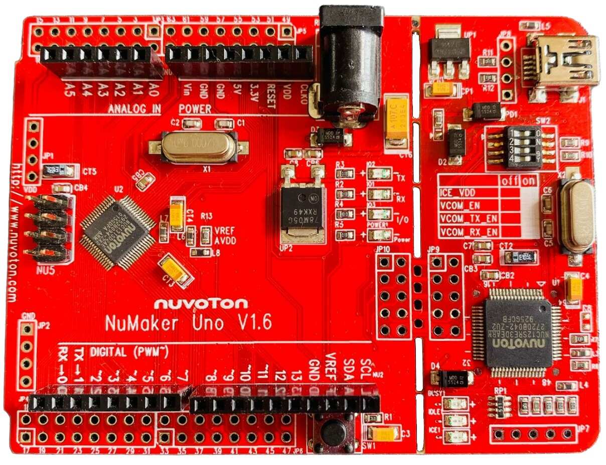
NuMaker UNO Development Board
The NuMaker UNO development board has left and right portion. The left portion is called NuMaker UNO target board and the right portion is Debug Adaptor called Nu-Link-Me. NuMaker UNO is pin-to-pin compatible with Arduino UNO revision 3.


The right portion is the debug adaptor called Nu-Link-Me which connects the USB port from the PC to the user’s target system (via the Serial Wired Debug port) and allows users to program and debug embedded programs on the target hardware. In addition, to loading external applications, it also provides virtual serial port (VCOM) functions. The debug messages through user-friendly NuLink–Me are displayed on the computer screen. The NuMaker UNO supports Arduino IDE, Keil, and IAR.
The NuMaker UNO development board provides the Arduino pin-out definition and extended connectors for each pin from the NUC131SD2AE MCU. It can be used to connect the application circuit board. The target board also supports a wide range of power supplies, such as from ICE, VDD & GND (JP1 & JP2), or from 7V ~ to 12V transformers. LED status is for power, I/O, TX, RX, and ICE.
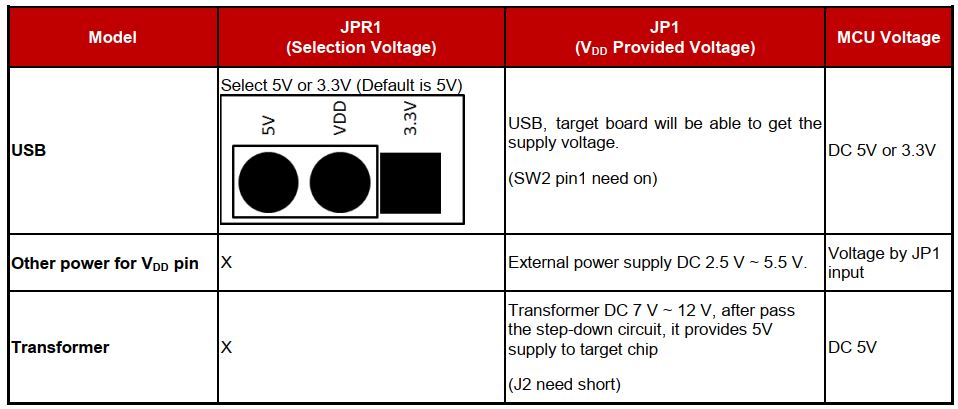
Power Settings
There are three methods to use the NuMaker UNO board to provide power to VDD.
- Method 1: Through the Nu-Link-Me USB interface. This power will go through LDO voltage regulator to 3.3V, JPR1 can be used to adjust VDD power to 5V or 3.3V.
- Method 2: Through the JP1 on the development board to VDD by DC 2.5V ~ 5.5V power supply.
- Method 3: Through a transformer (7V ~ 12V) and then the voltage is converted into 5V through the step-down circuit.
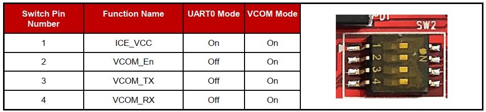
USB Virtual COM Function Setting
The Virtual COM function can be used for Arduino IDE, Keil, and IAR. To enable the VCOM function on Nu-Link Me, turn on all SW2 pins. To enable the UART0 function, turn off pin 2 ~ pin 4 on SW2. Please refer to the table below.
NuMaker UNO NUC131SD2AE Extended Connectors Layout
This is the NuMaker UNO NUC131SD2AE Extended Connectors Layout similar to Arduino UNO R3 Board.
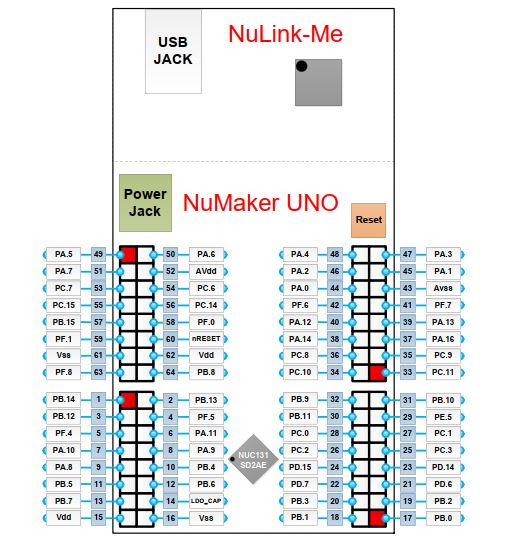
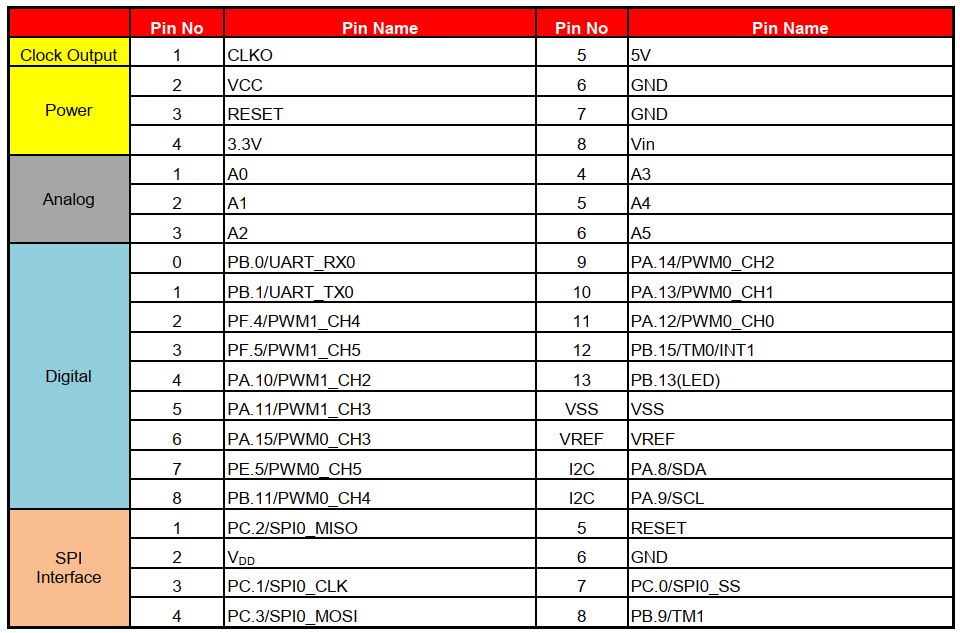
The NuMaker UNO provides the NUC131SD2AE target chip on board and the Arduino UNO extended connectors (NU1, NU2, NU3, NU4 and NU5) for LQFP64-pin. The table shows the pin assignment for NuMaker UNO.
Setting Up Arduino IDE
Visit https://www.arduino.cc/en/Main/Software, and download the latest Arduino.
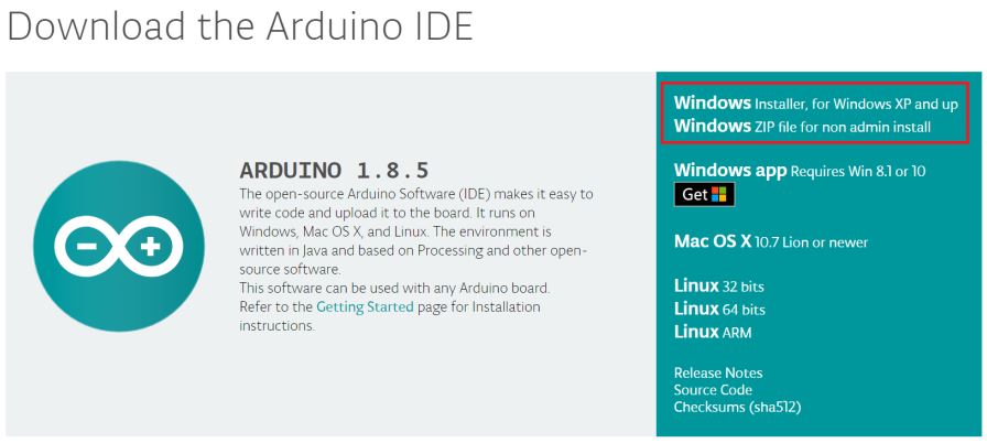
After downloading the Arduino IDE, install it into your computer system.
Please visit the Nuvoton NuMaker UNO official website (www.nuvoton.com/NuMaker_UNO) to download “Nu-Link USB Driver”.
After installing USB Driver, open your Arduino IDE. Then Go to File → Preferences, enter the following URL to textbox of ‘Additional Board Manager URLs:
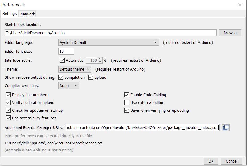
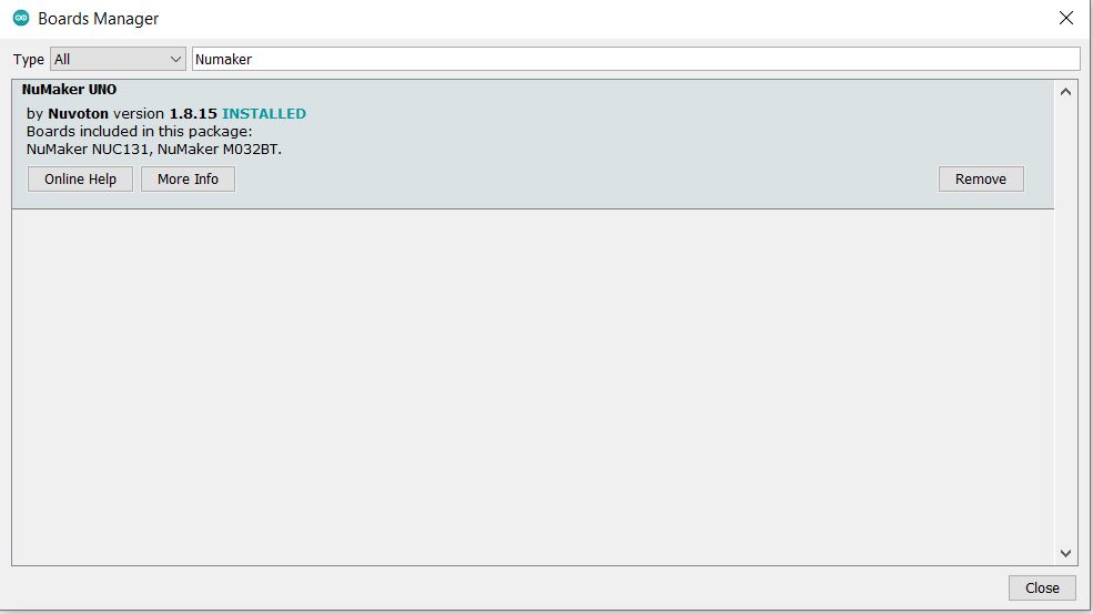
The go to Go to Tools → Board → Boards Manager on Arduino IDE and search for “Numaker”. The board manager will shown the NuMaker Board. You can install the board for the system.
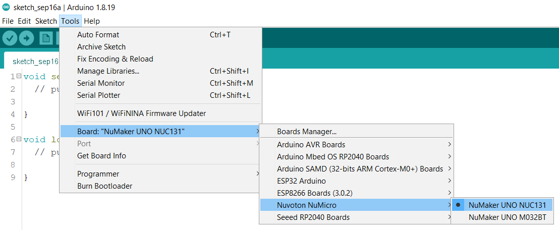
Now go to Tools and Select NuMaker UNO NUC131 Board from the board list.
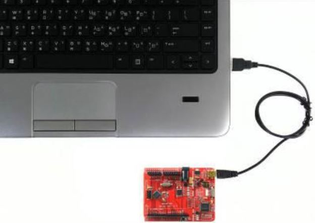
Now connect the NuMaker UNO Board to your computer via USB Cable.
Before connecting the NuMaker UNO development board to the computer, please enable SW2 of VCOM Function. All the SW2 pins shall be turned on.
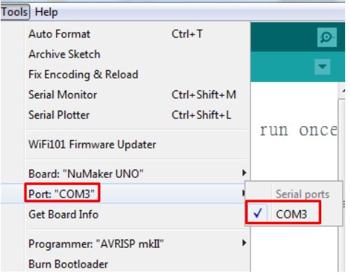
Open the device manager and check if the USB is detected. If it is not detected, please reinstall the NuLink USB Driver.
Now the device is ready and you can start programming the NuMaker UNO NUC131 via Arduino IDE.
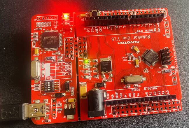
Example 1: Blinking of LED
Now the first program that we will test on this board is the blinking of LED. The on-board LED on the board is connected to Pin 13 of this board with a pull-up resistor.
Copy the following code and upload it to the board.
|
1 2 3 4 5 6 7 8 9 10 11 12 13 |
void setup() { // initialize digital pin LED_BUILTIN as an output. pinMode(LED_BUILTIN, OUTPUT); } void loop() { digitalWrite(LED_BUILTIN, HIGH); // turn the LED on (HIGH is the voltage level) delay(1000); // wait for a second digitalWrite(LED_BUILTIN, LOW); // turn the LED off by making the voltage LOW delay(1000); // wait for a second } |
While uploading the code the shell window will show you the following message.
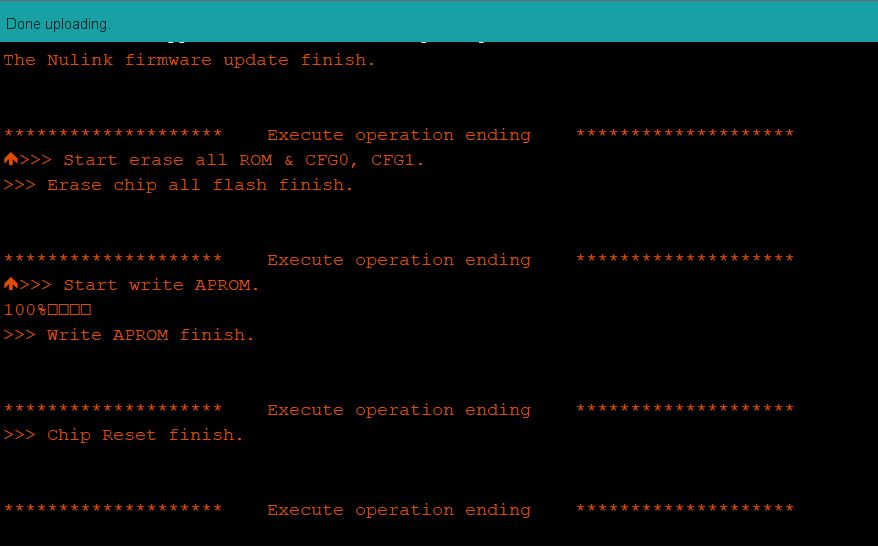
If you got this message, it means the code has been uploaded to your NuMaker UNO Board via Arduino IDE. The on-board LED on the board will blink after the interval of every one second.
Example 2: Controlling RGB LED
Now let us control the RGB LED using the UnMaker UNO Board. For this example you can use any RGB LED Module.
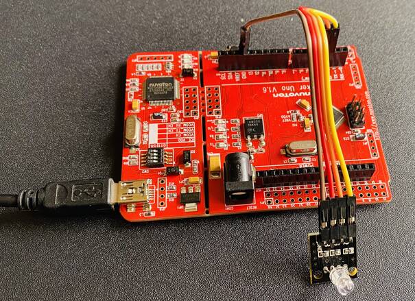
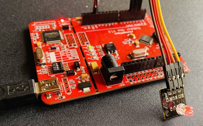
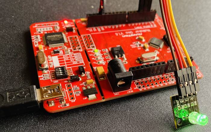
Connect the R, G, B & GND Pin of RGB LED to NuMaker UNO 2, 3, 4 & GND Pin as shown in the image below.
Now copy the following code and upload it to the NuMaker UNO Board.
|
1 2 3 4 5 6 7 8 9 10 11 12 13 14 15 16 17 18 19 20 21 22 23 24 25 26 27 28 29 30 31 32 33 34 |
const int lowestPin = 0; const int highestPin = 2; int rgbLed[]={ 2, 3, 4 }; /* R, G, B LED */ void setup() { // set pins 2 through 4 as outputs: for (int thisPin =lowestPin; thisPin <= highestPin; thisPin++) { pinMode(rgbLed[thisPin], OUTPUT); } } void loop() { // iterate over the pins: for (int thisPin =lowestPin; thisPin <= highestPin; thisPin++) { // fade the LED on thisPin from off to brightest: for (int brightness = 0; brightness < 255; brightness++) { analogWrite(rgbLed[thisPin], brightness); delay(2); } // fade the LED on thisPin from brithstest to off: for (int brightness = 255; brightness >= 0; brightness--) { analogWrite(rgbLed[thisPin], brightness); delay(2); } // pause between LEDs: delay(100); } } |
After uploading the code, the different color LED will glow as shown in the image below.
Example 3: Controlling LED Intensity using ADC Pin (Potentiometer)
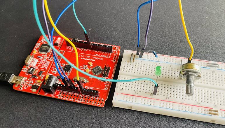
Now let us control the LED blinking intensity using the Analog Pin of NuMaker UNO Board. For this we will use a 10K Potentiometer and connect it pin to the Analog pin A0 of NuMaker UNO.
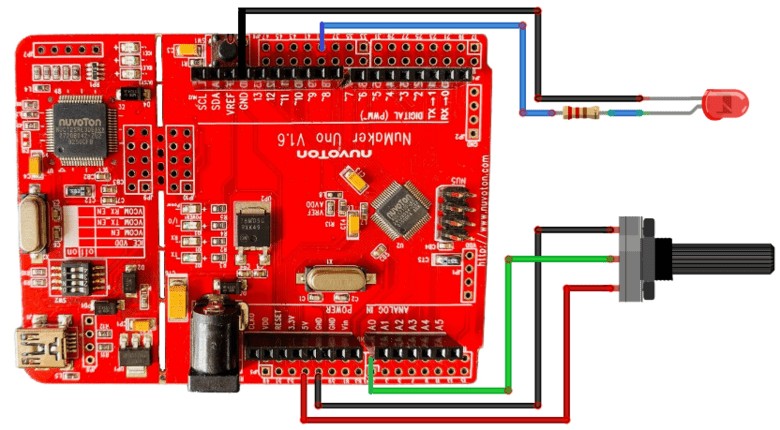
Connect the LED positive terminal to Pin 8 of NuMaker UNO via 560-ohm resistor.
Copy the following code and upload it to NuMaker UNO Board.
|
1 2 3 4 5 6 7 8 9 10 11 12 13 14 15 |
const int analog_ip = A0; const int LED = 8; int inputVal = 0; void setup() { pinMode (LED, OUTPUT); } void loop() { inputVal = analogRead(analog_ip); analogWrite (LED, inputVal/4); delay(100); } |
After uploading the code, rotate the potentiometer so that the LED blinking frequency can be controlled.

Example 4: Reading DHT11 Humidity Temperature Sensor Data
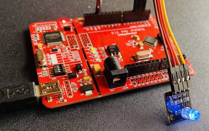
Let us interface the DHT11 Humidity and Temperature sensor with NuMaker UNO Board. Using the DHT11 Sensor, we can determine the environment temperature and humidity conditions. The connection diagram is fairly simple.
Connect the VCC, GND & output pin of DHT11 to 5V, GND & Pin 10 of UNO Board.
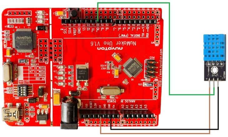
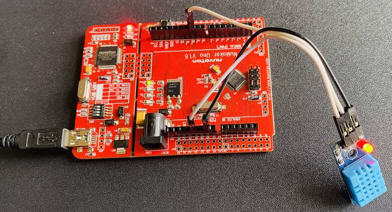
You can use jumper wires to connect the DHT11 Sensor to the board.
Copy the following code and upload it to the UNO Board.
|
1 2 3 4 5 6 7 8 9 10 11 12 13 14 15 16 17 18 19 20 21 22 23 24 25 26 27 28 29 30 31 32 33 34 35 36 37 38 39 40 41 |
#include <dht11.h> dht11 DHT; #define DHT11_PIN 10 void setup() { Serial.begin(115200); Serial.println("DHT TEST PROGRAM "); Serial.print("LIBRARY VERSION: "); Serial.println(DHT11LIB_VERSION); Serial.println(); Serial.println("Type,\tstatus,\tHumidity (%),\tTemperature (C)"); } void loop() { int chk; Serial.print("DHT11, \t"); chk = DHT.read(DHT11_PIN); // READ DATA switch (chk) { case DHTLIB_OK: Serial.print("OK,\t"); break; case DHTLIB_ERROR_CHECKSUM: Serial.print("Checksum error,\t"); break; case DHTLIB_ERROR_TIMEOUT: Serial.print("Time out error,\t"); break; default: Serial.print("Unknown error,\t"); break; } // DISPLAT DATA Serial.print(DHT.humidity,1); Serial.print(",\t"); Serial.println(DHT.temperature,1); delay(1500); } |
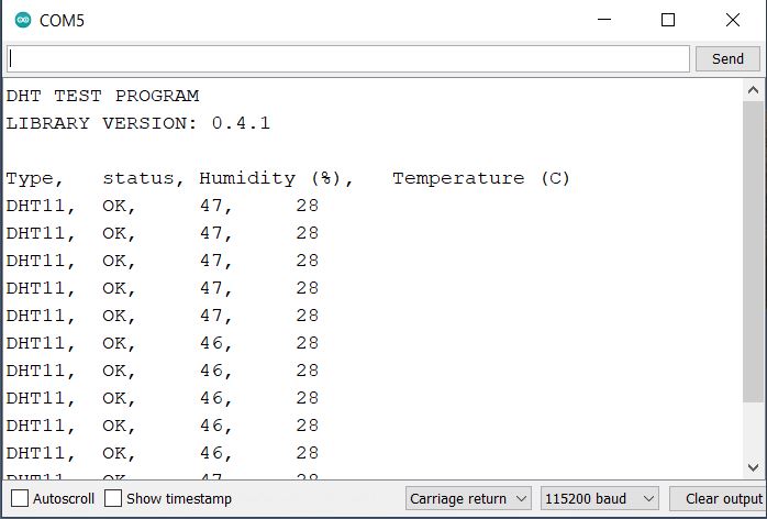
After uploading code, open the Serial Monitor, you will be able to see the Humidity and Temperature data.
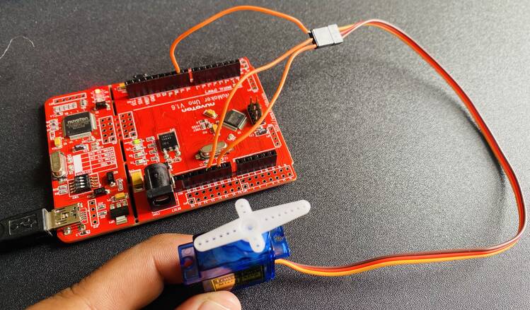
Example 5: Controlling Servo Motor using PWM Signal
Now let us control the servo motor using the PWM pin of NuMaker UNO Board. The connection diagram is fairly simple again.
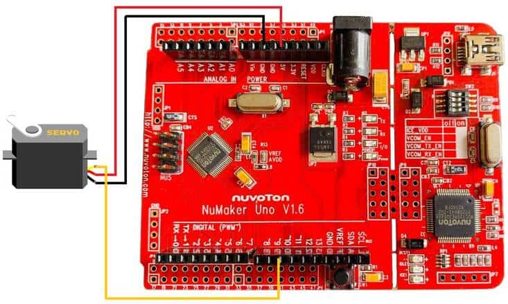
Connect the VCC, GND & Output pin of Servo Motor to 5V, GND & Pin 9 of UNO Board. You can use a jumper wire for connection.
Copy the following code and upload it to the UNO Board.
|
1 2 3 4 5 6 7 8 9 10 11 12 13 14 15 16 17 18 19 20 21 22 23 |
#include <nvtServo.h> Servo myservo; // create servo object to control a servo // twelve servo objects can be created on most boards int pos = 0; // variable to store the servo position void setup() { myservo.attach(9); // attaches the servo on pin 9 to the servo object } void loop() { for (pos = 0; pos <= 180; pos += 1) { // goes from 0 degrees to 180 degrees // in steps of 1 degree******************************************************************************************************** myservo.write(pos); // tell servo to go to position in variable 'pos' delay(15); // waits 15ms for the servo to reach the position } for (pos = 180; pos >= 0; pos -= 1) { // goes from 180 degrees to 0 degrees myservo.write(pos); // tell servo to go to position in variable 'pos' delay(15); // waits 15ms for the servo to reach the position } } |
After uploading the code, the Servo Motor shaft will rotate anticlockwise and clockwise direction.
Video Tutorial & Guide


