

Overview
In this project, we will build a Water Filling Machine using Flow Sensor & Arduino. The user inputs the total quantity of liquid using a 4×4 Keypad. The pump draws the exact quantity of water after receiving the user input. When an exact quantity is fulfilled, the pump disconnects automatically and stops further drawing of liquid. The maximum amount of liquid is up to 1500ml only.
Automatic Bottle Filling Machines are most commonly used in the beverages and soft drink industries. The project can be used in measuring the quantity of water, petrol, milk, drinks, and any other liquid based on user input. A better advancement of the project could be making a prepaid Liquid Dispenser Machine or a Conveyer based water filling system.
Bill of Materials
We need the following components to build this DIY Arduino Water Filling Machine project.

You can purchase the components from the given links.
| S.N. | Components | Quantity | Purchase Link |
|---|---|---|---|
| 1 | Arduino Nano | 1 | Amazon | AliExpress |
| 2 | YF-S201 Water Flow Sensor | 1 | Amazon | AliExpress |
| 3 | 16X2 LCD Display | 1 | Amazon | AliExpress |
| 4 | 10K Potentiometer | 1 | Amazon | AliExpress |
| 5 | 4x4 Keypad Matrix | 1 | Amazon | AliExpress |
| 6 | 5V Relay Module | 1 | Amazon | AliExpress |
| 7 | 5V DC Water Pump | 1 | Amazon | AliExpress |
| 8 | 9V DC Adapter | 1 | Amazon | AliExpress |
| 9 | 7805 Voltage Regulator IC | 1 | Amazon | AliExpress |
| 10 | 10uF/16V Capacitor | 1 | Amazon | AliExpress |
| 11 | 100uF/25V Capacitor | 1 | Amazon | AliExpress |
| 12 | DC Jack | 1 | Amazon | AliExpress |
YF-S201 Hall-Effect Water Flow Sensor

This is the YF-S201 Hall-Effect Water Flow Sensor used in this project. This sensor can be connected to the waterline as it has both an inlet and an outlet. Inside the sensor, there is a pinwheel that measures how much liquid has moved through it. There’s an integrated magnetic hall effect sensor that outputs an electrical pulse with every revolution.

The sensor comes with three wires:
1. Red (5-24VDC power)
2. Black (ground)
3. Yellow (Hall effect pulse output)
The water flow rate can be calculated by counting the pulses from the output of the sensor. Each pulse is approximately 2.25 milliliters. The pulse signal is a simple square wave so it’s quite easy to log and convert into liters per minute using the following formula.
4×4 Matrix Keypad

The 4×4 matrix keypad is an input device, it is usually used to provide input value in a project. It has 16 keys in total, which means it can provide 16 input values. The most interesting thing is it used only 8 GPIO pins of a microcontroller.

These Keypad modules are made of thin, flexible membrane material. The 4 x4 keypad module consists of 16 keys, these Keys are organized in a matrix of rows and columns. All these switches are connected to each other with a conductive trace. Normally there is no connection between rows and columns. When we will press a key, then a row and a column make contact.
Circuit: DIY Arduino Water Filling Machine
Lets have a look at a circuit diagram for Water Filling Machine using Flow Sensor & Arduino.

The circuit contains Arduino Nano Board, Water Flow Sensor, Relay Module, Water Pump, and LCD Display. The YF-S201 Water Flow Sensor is used to measure water flow during filling. The relay is the intermediate component between the Arduino board and the 5V DC water pump. It allows the Arduino board to control the water pump. Similarly, the 4×4 Matrix Keypad is used to input the quantity of Water that is to be dispersed. The LCD displays the flow Rate and Total Volume of water.

The LCD Display, Relay, Water Pump, and Water flow sensor is powered via a 5V from 7805 Voltage regulator IC. A DC barrel Jack is available where you can supply 9V using a 9V DC Adapter. In the circuit diagram, we connect the Relay input pin to D3 of Arduino and the Water Flow Sensor input pin to D2 of Arduino. The 5V DC pump is connected to the output of the 5V single-channel Relay Module. One end of the Water flow sensor takes water as input from the motor and gives output as water from the external end.
Connect the LCD 4, 6, 11, 12, 13, and 14 Pin to Arduino A0, A1, A2, A3, A4, and A5 pins. Also, connect the 4×4 Keypad matrix to Arduino D4, D5, D6, D7, D8, D9, D10, and D11 Pins.
Project PCB Gerber File & PCB Ordering Online
If you don’t want to assemble the circuit on a zero PCB and you want PCB for the project, then here is the PCB for you. I used EasyEDA to draw the schematic first.

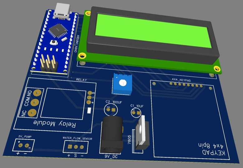
Then I converted the schematic to PCB. The PCB Board for Water Filling Machine using Flow Sensor & Arduino looks something like below.

The Gerber File for the PCB is given below. You can simply download the Gerber File and order the PCB from ALLPCB at 1$ only.
You can use this Gerber file to order high quality PCB for this project. To do that visit the ALLPCB official website by clicking here: https://www.allpcb.com/.

You can now upload the Gerber File by choosing the Quote Now option. From these options, you can choose the Material Type, Dimensions, Quantity, Thickness, Solder Mask Color and other required parameters.

After filling all details, select your country and shipping method. Finally you can place the order.
You can assemble the components on the PCB Board.
Source Code/Program
The program for the Water Filling Machine is written in Arduino IDE. Copy the following code and upload it to the Arduino Nano Board.
|
1 2 3 4 5 6 7 8 9 10 11 12 13 14 15 16 17 18 19 20 21 22 23 24 25 26 27 28 29 30 31 32 33 34 35 36 37 38 39 40 41 42 43 44 45 46 47 48 49 50 51 52 53 54 55 56 57 58 59 60 61 62 63 64 65 66 67 68 69 70 71 72 73 74 75 76 77 78 79 80 81 82 83 84 85 86 87 88 89 90 91 92 93 94 95 96 97 98 99 100 101 102 103 104 105 106 107 108 109 110 111 112 113 114 115 116 117 118 119 120 121 |
#include <Keypad.h> const int ROW_NUM = 4; const int COLUMN_NUM = 4; #include <LiquidCrystal.h> LiquidCrystal lcd(A0, A1, A2, A3, A4, A5); char keys[ROW_NUM][COLUMN_NUM] = { { '1', '2', '3', 'A' }, { '4', '5', '6', 'B' }, { '7', '8', '9', 'C' }, { '*', '0', '#', 'D' } }; byte pin_rows[ROW_NUM] = { 8, 9, 10, 11 }; byte pin_column[COLUMN_NUM] = { 4, 5, 6, 7 }; Keypad keypad = Keypad(makeKeymap(keys), pin_rows, pin_column, ROW_NUM, COLUMN_NUM); int sensorInterrupt = 0; int sensorPin = 2; int solenoidValve = 5; unsigned int SetPoint = 400; String code = ""; float calibrationFactor = 90; volatile byte pulseCount = 0; float flowRate = 0.0; unsigned int flowMilliLitres = 0; unsigned long totalMilliLitres = 0, volume = 0; unsigned long oldTime; const int relais_moteur = 3; void setup() { totalMilliLitres = 0; pinMode(relais_moteur, OUTPUT); lcd.begin(16, 2); lcd.setCursor(0, 0); lcd.print("Set Volume:"); Serial.begin(9600); pinMode(solenoidValve, OUTPUT); digitalWrite(solenoidValve, HIGH); pinMode(sensorPin, INPUT); digitalWrite(sensorPin, HIGH); attachInterrupt(sensorInterrupt, pulseCounter, FALLING); } void loop() { char key = keypad.getKey(); if (key) { code += key; lcd.setCursor(0, 1); lcd.print(code); delay(100); } if (key == 'D') { if (code.toInt() <= 1500) { volume = code.toInt(); } else { lcd.clear(); lcd.setCursor(0, 0); lcd.print("Set Volume:"); } code = ""; } if (totalMilliLitres < volume) { digitalWrite(relais_moteur, HIGH); if ((millis() - oldTime) > 1000) { detachInterrupt(sensorInterrupt); flowRate = ((1000.0 / (millis() - oldTime)) * pulseCount) / calibrationFactor; oldTime = millis(); flowMilliLitres = (flowRate / 60) * 1000; totalMilliLitres += flowMilliLitres; unsigned int frac; Serial.print("Flow rate :-"); Serial.print(flowMilliLitres, DEC); Serial.print("mL/Second"); Serial.print("\t"); lcd.clear(); lcd.setCursor(0, 0); lcd.print("Speed :"); lcd.print(flowMilliLitres); lcd.print(" ml/s"); Serial.print("Output Liquid Quantity: "); Serial.print(totalMilliLitres, DEC); Serial.println("mL"); Serial.print("\t"); lcd.setCursor(0, 1); lcd.print("Filled:"); lcd.print(totalMilliLitres); lcd.print(" ml"); if (totalMilliLitres > 40) { SetSolinoidValve(); } pulseCount = 0; attachInterrupt(sensorInterrupt, pulseCounter, FALLING); } } else { digitalWrite(relais_moteur, LOW); volume = 0; } } void pulseCounter() { pulseCount++; } void SetSolinoidValve() { digitalWrite(solenoidValve, LOW); } |
Testing DIY Arduino Water Filling Machine
After uploading the code to the Arduino Nano Board, the project is ready for testing. Power the entire circuit with a 5V Supply or using the USB port of Arduino Nano.

The set volume option will appear on the LCD Screen. We need to input the water quantity between 0-1500ml using the 4×4 Keypad.

After entering the volume, press the D button the water will start dispersing.
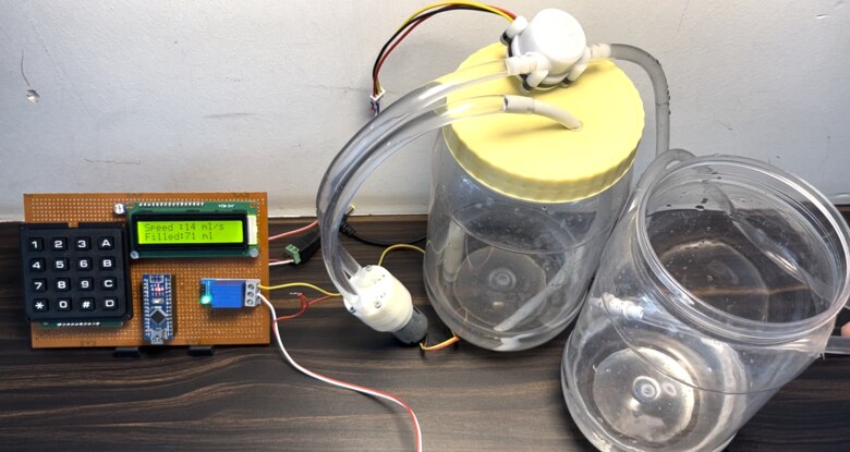
Once the filling is done, the Relay disconnects the water pump, and hence the water dispersing stops.
You can press the ‘A’ button to reset the water quantity and restart the process again.

The water filling machine project has a lot of applications in industries and you can use this as a prototype for a college demo.
Video Tutorial & Guide


")


1 Comment
Hello
What type of check valve do you use at the end of the hose?