

Overview
In this tutorial we will learn about the Interfacing of SSD1306 OLED Display with Raspberry Pi Pico. The OLED displays are one of the most attractive displays available for a microcontroller. It has a good view angle and pixel density which makes it reliable for displaying small level graphics.
The SSD1306 OLED display is available in both I2C & SPI Modules. But in this tutorial, we will use the 0.96″ I2C OLED Display as it requires only 2 wires for Interfacing. The Raspberry Pi Pico that comes with an RP2040 microcontroller has two Pairs of I2C Pins. You can use any of the I2C Pins of Raspberry Pi Pico for Interfacing SSD1306 OLED Display.
We will use Micropython code here to used OLED Display with Pico Board. The MicroPython IDE requires the SSD1306 Driver Code. After writing the driver code, we can write anything and display it on OLED Display. We will display the Analog value voltage from the Potentiometer on OLED Display. But before that we recommend you to go through Raspberry Pi Pico Getting Started Guide and also about the way of using the I2C Pin.
Bill of Materials
You cany purchase the required components for this tutorial from the following Amazon link.
| S.N. | Components Name | Quantity | Purchase Links |
|---|---|---|---|
| 1 | Raspberry Pi Pico | 1 | Amazon | AliExpress |
| 2 | 0.96" I2C OLED Display | 1 | Amazon | AliExpress |
| 3 | Potentiometer | 1 | Amazon | AliExpress |
| 4 | Breadboard | 1 | Amazon | AliExpress |
| 5 | Jumper Wires | 10 | Amazon | AliExpress |
SSD1306 OLED Display
The OLED displays are one of the most attractive displays available for a microcontroller because of their viewing angle and pixel density. This SSD1306 is a 0.96/1.3 inch blue OLED display module. You can interface this display module with any microcontroller using SPI/IIC protocols. It is having a resolution of 128×64. The package includes a display board, a display,4 pin male header pre-soldered to board.

OLED (Organic Light-Emitting Diode) is a self-light-emitting technology composed of a thin, multi-layered organic film placed between an anode and cathode. In contrast to LCD technology, OLED does not require a backlight. OLED possesses high application potential for virtually all types of displays and is regarded as the ultimate technology for the next generation of flat-panel displays.
Interfacing SSD1306 OLED Display with Raspberry Pi Pico
Now let us learn how we can interface SSD1306 OLED Display with Raspberry Pi Pico. The Raspberry Pi Pico Board has two pair of I2C Pins. You can use any of the pair of I2C Pins for interfacing applications. To learn more about the I2C Pins use & Applications you can use our Raspberry Pi Pico I2C Guide.
In this example we will feed the input value of analog voltage from Potentiometer to analog Pin GP28 of Raspberry Pi Pico. Then we will display the analog voltage on OLED Screen. The schematic is very simple and easy to use.

Connect the SDA & SCL Pin of OLED Display to PICO GP8 & GP9 Pin respectively. Connect the VCC & GND pin of OLED Display to 3.3V & GND Pin of Pico. You can use a breadboard to Assemble the entire circuit.
OLED Display Raspberry Pi Pico Code
In order to program the Raspberry Pi Pico Board, we will use MicroPython programming language. MicroPython is similar to Python. You can either use Thonny IDE or the uPyCraft IDE for programming and testing the board.
I prefer uPyCraft IDE for programming. The programming here is divided into two main parts:
1. SSD1306.py
2. Main.py
This is because the OLED Display requires SSD1306 Driver Code first. We have to write the code for the SSD1306 Driver first. After uploading the SSD1306 Code, we can then run the main.py code.

SSD1306.py
So in uPyCraft IDE, create a new file. Copy the following code & save the file by the name ssd1306.py.
|
1 2 3 4 5 6 7 8 9 10 11 12 13 14 15 16 17 18 19 20 21 22 23 24 25 26 27 28 29 30 31 32 33 34 35 36 37 38 39 40 41 42 43 44 45 46 47 48 49 50 51 52 53 54 55 56 57 58 59 60 61 62 63 64 65 66 67 68 69 70 71 72 73 74 75 76 77 78 79 80 81 82 83 84 85 86 87 88 89 90 91 92 93 94 95 96 97 98 99 100 101 102 103 104 105 106 107 108 109 110 111 112 113 114 115 116 117 118 119 120 121 122 123 124 125 126 127 128 129 130 131 132 133 134 135 136 137 138 139 140 141 142 143 144 145 146 147 148 149 150 151 152 153 154 |
# MicroPython SSD1306 OLED driver, I2C and SPI interfaces from micropython import const import framebuf # register definitions SET_CONTRAST = const(0x81) SET_ENTIRE_ON = const(0xA4) SET_NORM_INV = const(0xA6) SET_DISP = const(0xAE) SET_MEM_ADDR = const(0x20) SET_COL_ADDR = const(0x21) SET_PAGE_ADDR = const(0x22) SET_DISP_START_LINE = const(0x40) SET_SEG_REMAP = const(0xA0) SET_MUX_RATIO = const(0xA8) SET_COM_OUT_DIR = const(0xC0) SET_DISP_OFFSET = const(0xD3) SET_COM_PIN_CFG = const(0xDA) SET_DISP_CLK_DIV = const(0xD5) SET_PRECHARGE = const(0xD9) SET_VCOM_DESEL = const(0xDB) SET_CHARGE_PUMP = const(0x8D) # Subclassing FrameBuffer provides support for graphics primitives # http://docs.micropython.org/en/latest/pyboard/library/framebuf.html class SSD1306(framebuf.FrameBuffer): def __init__(self, width, height, external_vcc): self.width = width self.height = height self.external_vcc = external_vcc self.pages = self.height // 8 self.buffer = bytearray(self.pages * self.width) super().__init__(self.buffer, self.width, self.height, framebuf.MONO_VLSB) self.init_display() def init_display(self): for cmd in ( SET_DISP | 0x00, # off # address setting SET_MEM_ADDR, 0x00, # horizontal # resolution and layout SET_DISP_START_LINE | 0x00, SET_SEG_REMAP | 0x01, # column addr 127 mapped to SEG0 SET_MUX_RATIO, self.height - 1, SET_COM_OUT_DIR | 0x08, # scan from COM[N] to COM0 SET_DISP_OFFSET, 0x00, SET_COM_PIN_CFG, 0x02 if self.width > 2 * self.height else 0x12, # timing and driving scheme SET_DISP_CLK_DIV, 0x80, SET_PRECHARGE, 0x22 if self.external_vcc else 0xF1, SET_VCOM_DESEL, 0x30, # 0.83*Vcc # display SET_CONTRAST, 0xFF, # maximum SET_ENTIRE_ON, # output follows RAM contents SET_NORM_INV, # not inverted # charge pump SET_CHARGE_PUMP, 0x10 if self.external_vcc else 0x14, SET_DISP | 0x01, ): # on self.write_cmd(cmd) self.fill(0) self.show() def poweroff(self): self.write_cmd(SET_DISP | 0x00) def poweron(self): self.write_cmd(SET_DISP | 0x01) def contrast(self, contrast): self.write_cmd(SET_CONTRAST) self.write_cmd(contrast) def invert(self, invert): self.write_cmd(SET_NORM_INV | (invert & 1)) def show(self): x0 = 0 x1 = self.width - 1 if self.width == 64: # displays with width of 64 pixels are shifted by 32 x0 += 32 x1 += 32 self.write_cmd(SET_COL_ADDR) self.write_cmd(x0) self.write_cmd(x1) self.write_cmd(SET_PAGE_ADDR) self.write_cmd(0) self.write_cmd(self.pages - 1) self.write_data(self.buffer) class SSD1306_I2C(SSD1306): def __init__(self, width, height, i2c, addr=0x3C, external_vcc=False): self.i2c = i2c self.addr = addr self.temp = bytearray(2) self.write_list = [b"\x40", None] # Co=0, D/C#=1 super().__init__(width, height, external_vcc) def write_cmd(self, cmd): self.temp[0] = 0x80 # Co=1, D/C#=0 self.temp[1] = cmd self.i2c.writeto(self.addr, self.temp) def write_data(self, buf): self.write_list[1] = buf self.i2c.writevto(self.addr, self.write_list) class SSD1306_SPI(SSD1306): def __init__(self, width, height, spi, dc, res, cs, external_vcc=False): self.rate = 10 * 1024 * 1024 dc.init(dc.OUT, value=0) res.init(res.OUT, value=0) cs.init(cs.OUT, value=1) self.spi = spi self.dc = dc self.res = res self.cs = cs import time self.res(1) time.sleep_ms(1) self.res(0) time.sleep_ms(10) self.res(1) super().__init__(width, height, external_vcc) def write_cmd(self, cmd): self.spi.init(baudrate=self.rate, polarity=0, phase=0) self.cs(1) self.dc(0) self.cs(0) self.spi.write(bytearray([cmd])) self.cs(1) def write_data(self, buf): self.spi.init(baudrate=self.rate, polarity=0, phase=0) self.cs(1) self.dc(1) self.cs(0) self.spi.write(buf) self.cs(1) |
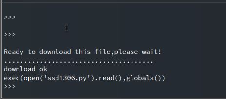
Now hit download & run button. So you will be able to see the SSD1306 driver saved in the Raspberry Pi Pico.
main.py
Open a new tab again in the uPyCraft IDE. Copy the following code and paste it on the uPyCraft IDE Window. Save the file by the name main.py.
|
1 2 3 4 5 6 7 8 9 10 11 12 13 14 15 16 17 18 19 20 21 22 23 24 25 26 27 28 29 30 31 32 33 34 35 36 37 38 39 40 41 42 |
# Display Image & text on I2C driven ssd1306 OLED display from machine import Pin, I2C from ssd1306 import SSD1306_I2C import framebuf import machine import utime sensor_temp = machine.ADC(28) conversion_factor = 3.3 / (65535) WIDTH = 128 # oled display width HEIGHT = 64 # oled display height i2c = I2C(0, scl=Pin(9), sda=Pin(8), freq=200000) # Init I2C using pins GP8 & GP9 (default I2C0 pins) print("I2C Address : "+hex(i2c.scan()[0]).upper()) # Display device address print("I2C Configuration: "+str(i2c)) # Display I2C config oled = SSD1306_I2C(WIDTH, HEIGHT, i2c) # Init oled display # Raspberry Pi logo as 32x32 bytearray buffer = bytearray(b"\x00\x00\x00\x00\x00\x00\x00\x00\x00\x00\x00\x00\x00|?\x00\x01\x86@\x80\x01\x01\x80\x80\x01\x11\x88\x80\x01\x05\xa0\x80\x00\x83\xc1\x00\x00C\xe3\x00\x00~\xfc\x00\x00L'\x00\x00\x9c\x11\x00\x00\xbf\xfd\x00\x00\xe1\x87\x00\x01\xc1\x83\x80\x02A\x82@\x02A\x82@\x02\xc1\xc2@\x02\xf6>\xc0\x01\xfc=\x80\x01\x18\x18\x80\x01\x88\x10\x80\x00\x8c!\x00\x00\x87\xf1\x00\x00\x7f\xf6\x00\x008\x1c\x00\x00\x0c \x00\x00\x03\xc0\x00\x00\x00\x00\x00\x00\x00\x00\x00\x00\x00\x00\x00") while True: reading = sensor_temp.read_u16() * conversion_factor # Load the raspberry pi logo into the framebuffer (the image is 32x32) fb = framebuf.FrameBuffer(buffer, 32, 32, framebuf.MONO_HLSB) # Clear the oled display in case it has junk on it. oled.fill(0) # Blit the image from the framebuffer to the oled display oled.blit(fb, 96, 0) # Add some text oled.text("ADC: ",5,8) oled.text(str(round(reading,2)),40,8) # Finally update the oled display so the image & text is displayed oled.show() |
Now again hit download & run button. The code will be saved to Raspberry Pi Pico Board.
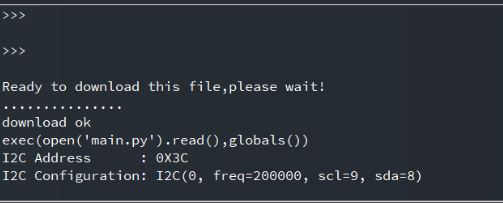
Now you are ready to go. The OLED Display will immediately start showing the Raspberry Pi Logo along with the Analog voltage value from the potentiometer.

You can rotate the potentiometer knob and see the OLED Display showing the different values.

This is how you can display the text or logo in an OLED Display using MicroPython Code. So interfacing SSD1306 OLED Display with Raspberry Pi Pico is so easy as this tutorial.
Video Tutorial & Guide


