

Overview
In this tutorial, we will learn Interfacing of 16×2 LCD Display with Raspberry Pi Pico. An LCD is an electronic display module that uses liquid crystal technology to produce a visible image. The 16×2 LCD display is a very basic module commonly used in electronic circuit applications. The 16×2 translates 16 characters per line in 2 such lines. In this LCD each character is displayed in a 5×8 pixel matrix.

Raspberry Pi Pico which was released a few months ago requires some LCD Display in engineering applications. Here we will go through the LCD Display details and features. The LCD Display is based on HD44780 Driver. There are I2C versions and non-I2C versions of LCD Display. We will take both of these LCDs as an example and interface with Raspberry Pi Pico. We will write MicroPython Code for Interfacing 16×2 LCD Display with Raspberry Pi Pico.
Bill of Materials
You need to purchase following components for building this project.
| S.N. | Components | Quantity | Purchase Links |
|---|---|---|---|
| 1 | Raspberry Pi Pico | 1 | Amazon | AliExpress |
| 2 | 16x2 LCD Display | 1 | Amazon | AliExpress |
| 3 | 10K Potentiometer | 1 | Amazon | AliExpress |
| 4 | 16x2 I2C LCD Display | 1 | Amazon | AliExpress |
| 5 | Jumper Wires | 10 | Amazon | AliExpress |
| 6 | BreadBoard | 11 | Amazon | AliExpress |
Brief Description of 16X2 LCD Display
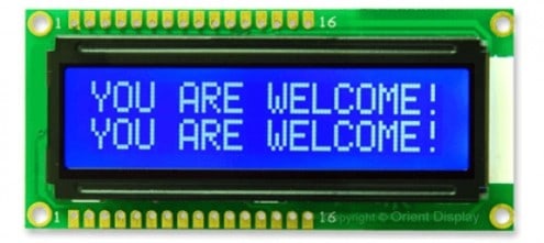
16×2 LCD is named so because it has 16 Columns and 2 Rows. So, it will have (16×2=32) 32 characters in total and each character will be made of 5×8 Pixel Dots. A Single character with all its Pixels is shown in the below picture.
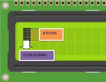
Each character has (5×8=40) 40 Pixels and for 32 Characters we will have (32×40) 1280 Pixels. Further, the LCD should also be instructed about the Position of the Pixels. Hence it will be a complicated task to handle everything with the help of a microcontroller. Hence the LCD uses an interface IC like HD44780. This IC is mounted on the backside of the LCD Module. You can check the HD44780 Datasheet for more information.
The function of this IC is to get the Commands and Data from the MCU and process them to display meaningful information on LCD Screen. The LCD operating Voltage is 4.7V to 5.3V & the Current consumption is 1mA without a backlight. It can work on both 8-bit and 4-bit mode
It can also display any custom-generated characters. These LCDs are available in Green and Blue Backlight.

There are two section pins on the whole 16×2 LCD module. Some of them are data pins and some are command pins. Somehow, every pin has a role in controlling a single pixel on the display.
16X2 I2C LCD Display
This display incorporates an I2C interface that requires only 2 pins on a microcontroller to the interface. The I2C interface is a daughter board attached to the back of the LCD module. The I2C address for these displays is either 0x3F or 0x27.

The adapter has an 8-Bit I/O Expander chip PCF8574. This chip converts the I2C data from a microcontroller into the parallel data required by the LCD display. There is a small trimpot to make fine adjustments to the contrast of the display. In addition, there is a jumper on the board that supplies power to the backlight.
Interfacing 16×2 LCD Display with Raspberry Pi Pico
Now, let us interface the 16×2 LCD Display with Raspberry Pi Pico. You can use Fritzing Software to draw the Schematic. You can assemble the circuit on breadboard as shown in the image below.

Connect the pin 1, 5 & 16 of LCD to GND of Raspberry Pi Pico. Similarly, connect the Pin 2 & 15 of LCD to 5V Pin, i.e Vbus of Raspberry Pi Pico. Connect the Pin 4, 6, 11, 12, 13, 14 of LCD Display to Raspberry Pi Pico GP16, GP17, GP18, GP19, GP20, GP21 Pin.
To adjust the LCD Contrast, connect a 10K Potentiometer at Pin 3 of LCD Display.

Source Code/Program
Raspberry Pi Pico supports MicroPython Program for interfacing 16×2 LCD Display. You can either use Thonny IDE or uPyCraft IDE for running the MicroPython Code.
Here is a complete code for interfacing the 16X2 HD44780 LCD with Raspberry Pi Pico. Copy the code to the IDE and save it with the name main.py.
|
1 2 3 4 5 6 7 8 9 10 11 12 13 14 15 16 17 18 19 20 21 22 23 24 25 26 27 28 29 30 31 32 33 34 35 36 37 38 39 40 41 42 43 44 45 46 47 48 |
import machine import utime rs = machine.Pin(16,machine.Pin.OUT) e = machine.Pin(17,machine.Pin.OUT) d4 = machine.Pin(18,machine.Pin.OUT) d5 = machine.Pin(19,machine.Pin.OUT) d6 = machine.Pin(20,machine.Pin.OUT) d7 = machine.Pin(21,machine.Pin.OUT) def pulseE(): e.value(1) utime.sleep_us(40) e.value(0) utime.sleep_us(40) def send2LCD4(BinNum): d4.value((BinNum & 0b00000001) >>0) d5.value((BinNum & 0b00000010) >>1) d6.value((BinNum & 0b00000100) >>2) d7.value((BinNum & 0b00001000) >>3) pulseE() def send2LCD8(BinNum): d4.value((BinNum & 0b00010000) >>4) d5.value((BinNum & 0b00100000) >>5) d6.value((BinNum & 0b01000000) >>6) d7.value((BinNum & 0b10000000) >>7) pulseE() d4.value((BinNum & 0b00000001) >>0) d5.value((BinNum & 0b00000010) >>1) d6.value((BinNum & 0b00000100) >>2) d7.value((BinNum & 0b00001000) >>3) pulseE() def setUpLCD(): rs.value(0) send2LCD4(0b0011)#8 bit send2LCD4(0b0011)#8 bit send2LCD4(0b0011)#8 bit send2LCD4(0b0010)#4 bit send2LCD8(0b00101000)#4 bit,2 lines?,5*8 bots send2LCD8(0b00001100)#lcd on, blink off, cursor off. send2LCD8(0b00000110)#increment cursor, no display shift send2LCD8(0b00000001)#clear screen utime.sleep_ms(2)#clear screen needs a long delay setUpLCD() rs.value(1) for x in 'Hello World!': send2LCD8(ord(x)) |
Hence, once you run the code, the LCD Display will start showing the Hello World! message in LCD Display.

Interfacing 16×2 I2C LCD Display with Raspberry Pi Pico
The above code is valid for 16×2 LCD Display without any I2C Module. The PCF8574 I2C or SMBus module simplifies the above connection. Instead of using so many wiring, you can use this IC Module and convert the data output lines just to 2 pins.
Hence the LCD Display becomes an I2C Display with an I2C address of 0x27. The connection between the Raspberry Pi Pico and I2C LCD is very simples as shown below in the schematic.

Connect the LCD VCC & GND Pin to Raspberry Pi Pico 5V & GND Pin respectively. Connect the SDA & SCL pin of LCD to Raspberry Pi Pico GP8 & GP9 respectively.

Source Code/Program
The program for this section is divided into 3 parts. We need to write some driver code as well as I2C protocol code for this part.
Copy all this code and then save all of the 3 codes to Raspberry Pi Pico Board.
lcd_api.py
|
1 2 3 4 5 6 7 8 9 10 11 12 13 14 15 16 17 18 19 20 21 22 23 24 25 26 27 28 29 30 31 32 33 34 35 36 37 38 39 40 41 42 43 44 45 46 47 48 49 50 51 52 53 54 55 56 57 58 59 60 61 62 63 64 65 66 67 68 69 70 71 72 73 74 75 76 77 78 79 80 81 82 83 84 85 86 87 88 89 90 91 92 93 94 95 96 97 98 99 100 101 102 103 104 105 106 107 108 109 110 111 112 113 114 115 116 117 118 119 120 121 122 123 124 125 126 127 128 129 130 131 132 133 134 135 136 137 138 139 140 141 142 143 144 145 146 147 148 149 150 151 152 153 154 155 156 157 158 159 160 161 162 163 164 165 166 167 168 169 170 171 172 173 174 175 176 177 178 179 180 181 182 183 184 185 186 187 188 |
import time class LcdApi: LCD_CLR = 0x01 # DB0: clear display LCD_HOME = 0x02 # DB1: return to home position LCD_ENTRY_MODE = 0x04 # DB2: set entry mode LCD_ENTRY_INC = 0x02 # --DB1: increment LCD_ENTRY_SHIFT = 0x01 # --DB0: shift LCD_ON_CTRL = 0x08 # DB3: turn lcd/cursor on LCD_ON_DISPLAY = 0x04 # --DB2: turn display on LCD_ON_CURSOR = 0x02 # --DB1: turn cursor on LCD_ON_BLINK = 0x01 # --DB0: blinking cursor LCD_MOVE = 0x10 # DB4: move cursor/display LCD_MOVE_DISP = 0x08 # --DB3: move display (0-> move cursor) LCD_MOVE_RIGHT = 0x04 # --DB2: move right (0-> left) LCD_FUNCTION = 0x20 # DB5: function set LCD_FUNCTION_8BIT = 0x10 # --DB4: set 8BIT mode (0->4BIT mode) LCD_FUNCTION_2LINES = 0x08 # --DB3: two lines (0->one line) LCD_FUNCTION_10DOTS = 0x04 # --DB2: 5x10 font (0->5x7 font) LCD_FUNCTION_RESET = 0x30 # See "Initializing by Instruction" section LCD_CGRAM = 0x40 # DB6: set CG RAM address LCD_DDRAM = 0x80 # DB7: set DD RAM address LCD_RS_CMD = 0 LCD_RS_DATA = 1 LCD_RW_WRITE = 0 LCD_RW_READ = 1 def __init__(self, num_lines, num_columns): self.num_lines = num_lines if self.num_lines > 4: self.num_lines = 4 self.num_columns = num_columns if self.num_columns > 40: self.num_columns = 40 self.cursor_x = 0 self.cursor_y = 0 self.implied_newline = False self.backlight = True self.display_off() self.backlight_on() self.clear() self.hal_write_command(self.LCD_ENTRY_MODE | self.LCD_ENTRY_INC) self.hide_cursor() self.display_on() def clear(self): """Clears the LCD display and moves the cursor to the top left corner. """ self.hal_write_command(self.LCD_CLR) self.hal_write_command(self.LCD_HOME) self.cursor_x = 0 self.cursor_y = 0 def show_cursor(self): """Causes the cursor to be made visible.""" self.hal_write_command(self.LCD_ON_CTRL | self.LCD_ON_DISPLAY | self.LCD_ON_CURSOR) def hide_cursor(self): """Causes the cursor to be hidden.""" self.hal_write_command(self.LCD_ON_CTRL | self.LCD_ON_DISPLAY) def blink_cursor_on(self): """Turns on the cursor, and makes it blink.""" self.hal_write_command(self.LCD_ON_CTRL | self.LCD_ON_DISPLAY | self.LCD_ON_CURSOR | self.LCD_ON_BLINK) def blink_cursor_off(self): """Turns on the cursor, and makes it no blink (i.e. be solid).""" self.hal_write_command(self.LCD_ON_CTRL | self.LCD_ON_DISPLAY | self.LCD_ON_CURSOR) def display_on(self): """Turns on (i.e. unblanks) the LCD.""" self.hal_write_command(self.LCD_ON_CTRL | self.LCD_ON_DISPLAY) def display_off(self): """Turns off (i.e. blanks) the LCD.""" self.hal_write_command(self.LCD_ON_CTRL) def backlight_on(self): """Turns the backlight on. This isn't really an LCD command, but some modules have backlight controls, so this allows the hal to pass through the command. """ self.backlight = True self.hal_backlight_on() def backlight_off(self): """Turns the backlight off. This isn't really an LCD command, but some modules have backlight controls, so this allows the hal to pass through the command. """ self.backlight = False self.hal_backlight_off() def move_to(self, cursor_x, cursor_y): """Moves the cursor position to the indicated position. The cursor position is zero based (i.e. cursor_x == 0 indicates first column). """ self.cursor_x = cursor_x self.cursor_y = cursor_y addr = cursor_x & 0x3f if cursor_y & 1: addr += 0x40 # Lines 1 & 3 add 0x40 if cursor_y & 2: # Lines 2 & 3 add number of columns addr += self.num_columns self.hal_write_command(self.LCD_DDRAM | addr) def putchar(self, char): """Writes the indicated character to the LCD at the current cursor position, and advances the cursor by one position. """ if char == '\n': if self.implied_newline: # self.implied_newline means we advanced due to a wraparound, # so if we get a newline right after that we ignore it. pass else: self.cursor_x = self.num_columns else: self.hal_write_data(ord(char)) self.cursor_x += 1 if self.cursor_x >= self.num_columns: self.cursor_x = 0 self.cursor_y += 1 self.implied_newline = (char != '\n') if self.cursor_y >= self.num_lines: self.cursor_y = 0 self.move_to(self.cursor_x, self.cursor_y) def putstr(self, string): """Write the indicated string to the LCD at the current cursor position and advances the cursor position appropriately. """ for char in string: self.putchar(char) def custom_char(self, location, charmap): """Write a character to one of the 8 CGRAM locations, available as chr(0) through chr(7). """ location &= 0x7 self.hal_write_command(self.LCD_CGRAM | (location << 3)) self.hal_sleep_us(40) for i in range(8): self.hal_write_data(charmap[i]) self.hal_sleep_us(40) self.move_to(self.cursor_x, self.cursor_y) def hal_backlight_on(self): """Allows the hal layer to turn the backlight on. If desired, a derived HAL class will implement this function. """ pass def hal_backlight_off(self): """Allows the hal layer to turn the backlight off. If desired, a derived HAL class will implement this function. """ pass def hal_write_command(self, cmd): """Write a command to the LCD. It is expected that a derived HAL class will implement this function. """ raise NotImplementedError def hal_write_data(self, data): """Write data to the LCD. It is expected that a derived HAL class will implement this function. """ raise NotImplementedError def hal_sleep_us(self, usecs): """Sleep for some time (given in microseconds).""" time.sleep_us(usecs) |
pico_i2c_lcd.py
|
1 2 3 4 5 6 7 8 9 10 11 12 13 14 15 16 17 18 19 20 21 22 23 24 25 26 27 28 29 30 31 32 33 34 35 36 37 38 39 40 41 42 43 44 45 46 47 48 49 50 51 52 53 54 55 56 57 58 59 60 61 62 63 64 65 66 67 68 69 70 71 72 73 74 75 76 77 |
from lcd_api import LcdApi from machine import I2C from time import sleep_ms DEFAULT_I2C_ADDR = 0x27 # Defines shifts or masks for the various LCD line attached to the PCF8574 MASK_RS = 0x01 MASK_RW = 0x02 MASK_E = 0x04 SHIFT_BACKLIGHT = 3 SHIFT_DATA = 4 class I2cLcd(LcdApi): """Implements a character based lcd connected via PCF8574 on i2c.""" def __init__(self, i2c, i2c_addr, num_lines, num_columns): self.i2c = i2c self.i2c_addr = i2c_addr self.i2c.writeto(self.i2c_addr, bytearray([0])) sleep_ms(20) # Allow LCD time to powerup # Send reset 3 times self.hal_write_init_nibble(self.LCD_FUNCTION_RESET) sleep_ms(5) # need to delay at least 4.1 msec self.hal_write_init_nibble(self.LCD_FUNCTION_RESET) sleep_ms(1) self.hal_write_init_nibble(self.LCD_FUNCTION_RESET) sleep_ms(1) # Put LCD into 4 bit mode self.hal_write_init_nibble(self.LCD_FUNCTION) sleep_ms(1) LcdApi.__init__(self, num_lines, num_columns) cmd = self.LCD_FUNCTION if num_lines > 1: cmd |= self.LCD_FUNCTION_2LINES self.hal_write_command(cmd) def hal_write_init_nibble(self, nibble): """Writes an initialization nibble to the LCD. This particular function is only used during intiialization. """ byte = ((nibble >> 4) & 0x0f) << SHIFT_DATA self.i2c.writeto(self.i2c_addr, bytearray([byte | MASK_E])) self.i2c.writeto(self.i2c_addr, bytearray([byte])) def hal_backlight_on(self): """Allows the hal layer to turn the backlight on.""" self.i2c.writeto(self.i2c_addr, bytearray([1 << SHIFT_BACKLIGHT])) def hal_backlight_off(self): """Allows the hal layer to turn the backlight off.""" self.i2c.writeto(self.i2c_addr, bytearray([0])) def hal_write_command(self, cmd): """Writes a command to the LCD. Data is latched on the falling edge of E. """ byte = ((self.backlight << SHIFT_BACKLIGHT) | (((cmd >> 4) & 0x0f) << SHIFT_DATA)) self.i2c.writeto(self.i2c_addr, bytearray([byte | MASK_E])) self.i2c.writeto(self.i2c_addr, bytearray([byte])) byte = ((self.backlight << SHIFT_BACKLIGHT) | ((cmd & 0x0f) << SHIFT_DATA)) self.i2c.writeto(self.i2c_addr, bytearray([byte | MASK_E])) self.i2c.writeto(self.i2c_addr, bytearray([byte])) if cmd <= 3: # The home and clear commands require a worst case delay of 4.1 msec sleep_ms(5) def hal_write_data(self, data): """Write data to the LCD.""" byte = (MASK_RS | (self.backlight << SHIFT_BACKLIGHT) | (((data >> 4) & 0x0f) << SHIFT_DATA)) self.i2c.writeto(self.i2c_addr, bytearray([byte | MASK_E])) self.i2c.writeto(self.i2c_addr, bytearray([byte])) byte = (MASK_RS | (self.backlight << SHIFT_BACKLIGHT) | ((data & 0x0f) << SHIFT_DATA)) self.i2c.writeto(self.i2c_addr, bytearray([byte | MASK_E])) self.i2c.writeto(self.i2c_addr, bytearray([byte])) |
main.py
|
1 2 3 4 5 6 7 8 9 10 11 12 |
from pico_i2c_lcd import I2cLcd from machine import I2C from machine import Pin import utime as time i2c = I2C(id=1,scl=Pin(9),sda=Pin(8),freq=100000) lcd = I2cLcd(i2c, 0x27, 2, 16) while True: lcd.move_to(2,0) lcd.putstr('Hello world') |
Once, you run all these codes on Raspberry Pi Pico, the LCD will start displaying the Hello World Message.

If you want the Scrolling effect of the text and characters on 16X2 I2C LCD Display, you may refer to the post: Billboard Scrolling


10 Comments
It is not showing hello world, just a light blink
following is my code
from pico_i2c_lcd import I2cLcd
from machine import I2C
from machine import Pin
import utime as time
i2c = I2C(id=0,sda=Pin(8),scl=Pin(9),freq=100000)
lcd = I2cLcd(i2c, 0x3F, 2, 16)
while True:
lcd.move_to(2,0)
lcd.putstr(‘Hello world’)
i changed id to 0 because on 1 it gives ValueError: bad SCL pin
i changed address because on 0x27 it gives error OSError: [Errno 5] EIO
Any advice, thanks in advance
Hello Sachin!
I have had the same problem, but I solved it by using first I2C and other pins:
Req’d: lcd_api.py, pico_i2c_lcd.py
from pico_i2c_lcd import I2cLcd
from machine import I2C
from machine import Pin
import utime as time
i2c = I2C(id=0,scl=Pin(1),sda=Pin(0),freq=100000)
lcd = I2cLcd(i2c, 0x27, 2, 16)
while True:
lcd.move_to(2,0)
lcd.putstr(‘Hello world’)
lcd.move_to(2,1)
lcd.putstr(‘* Zeile 2 *’)
The schematic for the non-I2C needs updating. Pin 15 on the lcd needs to route to 5v (vbus), as per the written description. Also, 1 wire between the Pico and LCD is missing.
After making those adjustments, code worked great.
Most code online assumes your LCD has the daughter board and only needs 4 wires.
Thanks for your distinguishing between the two types of 1602a LCDs !!!
Thank you Sanjay — very helpful. However it would be worth mentioning when using PCF8574 I2C module that if nothing appears on the display, the fix could be as simple as adjusting the trim pot on the board! I was puzzling over this, looking for an error in my wiring and then for an error in your code, for a couple of hours before the obvious occurred to me!
THanks for the advise, I too had the same problem but after following your advise on changing the id to 0 it all worked fine
i2c = I2C(id=0,scl=Pin(9),sda=Pin(8),freq=100000)
lcd = I2cLcd(i2c, 0x27, 2, 1
Is there a way for the LCD to display a temperature sensor reading? I get the error ‘float object not iterable’.
from pico_i2c_lcd import I2cLcd
from machine import I2C
from machine import Pin
import utime as time
i2c = I2C(id=0,scl=Pin(9),sda=Pin(8),freq=100000)
lcd = I2cLcd(i2c, 0x27, 2, 16)
sensor_temp = machine.ADC(4)
conversion_factor = 3.3 / (65535)
while True:
reading = sensor_temp.read_u16() * conversion_factor
temperature = 27 – (reading – 0.706)/0.001721
just replace the “–” with “-”
than “-” is considered as minus symbol and the mathematical operation can happen
OMG THANK YOU THANK YOU, I would have never figured it out. Anyone else having problems should definitely look into this and don’t ignore it like I did!!!!!
Thank you so much. I spent hours thinking I was doing something wrong!
I have a Grove 2×16 LCD with I2C but when running the code I get a first row with white blocks, second row blanks. I get no errors when running the program below:
from pico_i2c_lcd import I2cLcd
from machine import I2C
from machine import Pin
import utime as time
i2c = I2C(0,scl=Pin(1),sda=Pin(0),freq=100000)
lcd = I2cLcd(i2c, 0x3E, 2, 16)
while True:
lcd.move_to(2,0)
lcd.putstr(‘Hello world’)
I