

Overview: LoRa Based Soil Moisture Monitoring
In this Smart Agriculture Project, we will make LoRa Based Soil Moisture Monitoring System Project. The LoRa Soil Moisture Module is the robust, simple, and fully wireless solution to soil moisture measurement for agriculture.
The LoRa Soil Moisture Sensor Node is made up of Capacitive Soil Moisture Sensor PCB. The PCB Combines ATmega328 microcontroller with LoRa Module RFM95. The gateway is an ESP32 LoRa Shield that fits on MakePython ESP32 Module. This gateway uploads the data to the cloud and is capable of managing an unlimited number of wireless soil moisture sensors. The revolutionary Sensor soil moisture solution is self-sustaining, wireless, and remote.

Before moving ahead you can check our previous project using LoRa Soil Moisture Sensor. The LoRa Gateway creates a WebServer where you can monitor Soil Moisture Data. You can also make your own LoRa WebServer Gateway.
Bill of Materials
The following is the list of components that you need for this project. You can purchase all the components online from the official Manufacturer of the Sensor.
| S.N. | Components | Quantity | Purchase Links |
|---|---|---|---|
| 1 | LoRa Soil Moisture Sensor | 1 | Makerfabs |
| 2 | LoRa ESP32 Gateway Shield | 1 | Makerfabs |
| 3 | MakePython ESP32 Board | 1 | Makerfabs |
| 4 | FTDI Module | 1 | Amazon | AliExpress |
| 5 | Battery | 2 | Amazon |
| 6 | Type C USB Cable | 1 | Amazon | AliExpress |
LoRa Sensor Node Transmitter
The Transmitter part consists of Lora soil moisture sensor and AHT10 Humidity/Temperature Sensor. The microcontroller used in this board is Atmel’s Atmega328P which supports Arduino Programming. The AHT10 Sensor collects local air temperature & humidity. The Capacitive Soil Moisture Sensor detects the soil humidity. The Sensor is based on 555-Timer IC. The Lora Radio and the Soil Moisture Sensor must have the same work frequency. Otherwise, it receive nothing from another. The transmitter transmits the local environment data to the gateway using LoRa Module RFM95.

The Lora Transmitter is powered by a pair of AAA Battery. The device transmits the data regularly after the interval of a few minutes and then goes to sleep mode for saving the Battery Power. The sensor function could be shut down or they can be only powered ON for a short time based on code and hardware setup. Thus because of sleep mode and low power consumption mode, the battery life can be extended up to several months. The capacitive soil Moisture sensor is coated with waterproof paint, so it doesn’t have any corrosion effect even the sensor is dipped in the soil for a long time. The module suits for applications for smart-farm, irrigation, agriculture, etc.
The ATmega328 chip has default Arduino bootloader and thus can be easily programmed using Arduino IDE. We just need a USB-to-TTL Converter Module like CP2104 Module.

Power Consumption & Sleep Mode
MCU Power Consumption at 1MHz, 1.8V, 25°C
– Active Mode: 0.2mA
– Power-down Mode: 0.1µA
– Power-save Mode: 0.75µA (Including 32kHz RTC)
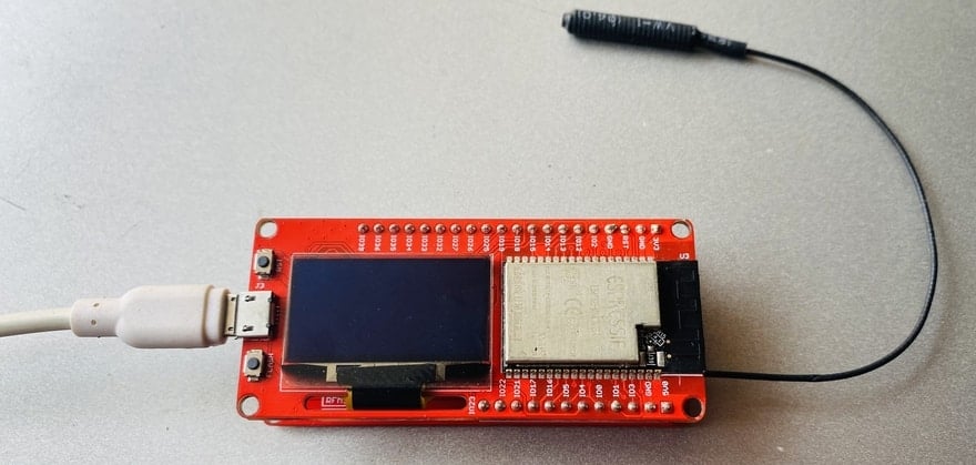
ESP32 LoRa Gateway
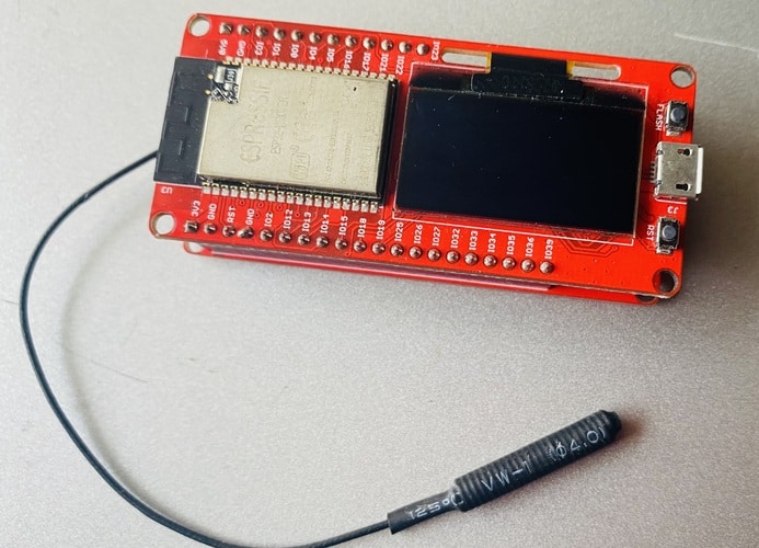
To create the LoraWAN, a gateway is needed to make all the items in Lora networks assessable to the Internet. This Lora Gateway based on the MakePython ESP32 and 2 Channel Lora Expansion board. The Makepython Lora transceivers feature the LoRaTM long-range modem that provides ultra-long range spread spectrum communication and high interference immunity whilst minimizing current consumption.

The combined board contains the LoRa Module RFM95W which handles the 433MHz band while the ESP32 takes care of Bluetooth or WiFi capabilities. The Lora Gateway offers bandwidth options ranging from 7.8125kHz to 500 kHz with spreading factors ranging from 6 to 12.
The two Lora gateways are used for long-distance communication in the complex environment of the city. The actual test distance reaches 2.8 kilometers. If the interference is small in the suburbs, the distance will be farther.
Block Diagram: LoRa Based Soil Moisture Monitoring System
The following is the block diagram of entire LoRa Based Soil Moisture Monitoring System Project. The block contains mutiple wireless Network along with LoRa Sensor Node & the Gateway.
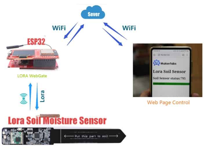
The LoRa Soil Moisture Sensor acts a Sensor Node. It reads the soil moisture value in analog form after an interval of every 5 seconds or more. You can set the timing in the code part. The sensor node sends the data to Gateway using the LoRa Radio.
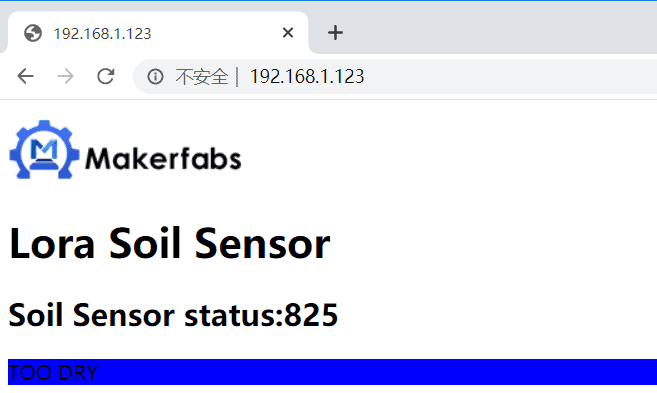
The receiver is also made using ESP32 & LoRa Module. The receiver collects the data from one or more Sensor Nodes. Then receiver creates a local Web Server using the ESP32 inbuilt library function. You can access the web page using the IP Address that appears on the OLED display on ESP32.
The webpage will display the Soil Moisture Analog data value and indicates whether the soil moisture value is good, normal, or excess.
Setting up Loara Soil Moisture Transmitter Part
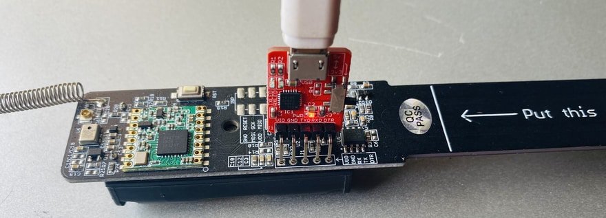
In order to upload the Code to the Transmitter Part you need to solder a 5 Pin Male Header pin. So first Solder the Male header pin here.

Now you need to connect USB-to-UART Module to upload the Code the Atmega328 Chip using Arduino IDE. Make a connection between the USB-to-UART Module as follow.

Note that the DTR in the USB-to-UART converter is needed to connect to the “Reset” pin for Arduino sketch uploading. If there is no DTR, you may need to press the “reset” button manually for uploading the code.
Install AAA Battery on the backside of the Module.
Now in order to program the Board using Arduino IDE for Lora agriculture sensor Board, there is already a default package board installed on Arduino IDE.
From the top Arduino IDE menu, select Tools-> Board-> Arduino Pro or Pro Mini. Also select Tools-> Processor->Atmega328P(3.3V,8Mhz).

Now your LoRa Sender Part is ready. You can insert the LoRa Soil Moisture Sensor in the soil.

Source Code/Program for Sensor Node
The code requires RFM95 LIbrary for compilation. You can get the Radio Head Library and add it to the Arduino Library Folder.
|
1 2 3 4 5 6 7 8 9 10 11 12 13 14 15 16 17 18 19 20 21 22 23 24 25 26 27 28 29 30 31 32 33 34 35 36 37 38 39 40 41 42 43 44 45 46 47 48 49 50 51 52 53 54 55 56 57 58 59 60 61 62 63 64 65 66 67 68 69 70 71 72 73 74 75 76 77 78 79 80 81 82 83 |
#include <SPI.h> #include <ArduinoJson.h> #include "RH_RF95.h" #define RFM95_CS 10 #define RFM95_RST 4 #define RFM95_INT 2 #define RF95_FREQ 433.0 #define RF95_PREMABLE_LENGTH 8 #define SENSOR_PIN A2 //土壤湿度传感器adc引脚 int sensorValue = 0; int sensorPowerCtrlPin = 5; //Lora芯片对象 RH_RF95 rf95(RFM95_CS, RFM95_INT); void setup() { Serial.begin(115200); pinMode(sensorPowerCtrlPin, OUTPUT); //重启 pinMode(RFM95_RST, OUTPUT); digitalWrite(RFM95_RST, HIGH); delay(10); digitalWrite(RFM95_RST, LOW); delay(10); digitalWrite(RFM95_RST, HIGH); delay(10); //初始化 while (!rf95.init()) { Serial.println("LoRa radio init failed"); while (1) ; } Serial.println("LoRa radio init OK!"); //设置频率 if (!rf95.setFrequency(RF95_FREQ)) { Serial.println("setFrequency failed"); while (1) ; } Serial.print("Set Freq to: "); Serial.println(RF95_FREQ); //设置发射功率 rf95.setTxPower(23, false); //设置前导码长度 rf95.setPreambleLength(RF95_PREMABLE_LENGTH); Serial.print("Set setPreambleLength to: "); Serial.println(RF95_PREMABLE_LENGTH); //rf95.printRegisters(); digitalWrite(sensorPowerCtrlPin, HIGH); } //土壤传感器代码 void loop() { sensorValue = analogRead(SENSOR_PIN); String temp = String(sensorValue); Serial.println(sensorValue); String message = "SOIL" + temp; Serial.println(message); // Send a message to rf95_server uint8_t radioPacket[message.length() + 1]; message.toCharArray(radioPacket, message.length() + 1); radioPacket[message.length() + 1] = '\0'; Serial.println("Sending..."); delay(10); rf95.send((uint8_t *)radioPacket, message.length() + 1); delay(5000); //unit: ms } |
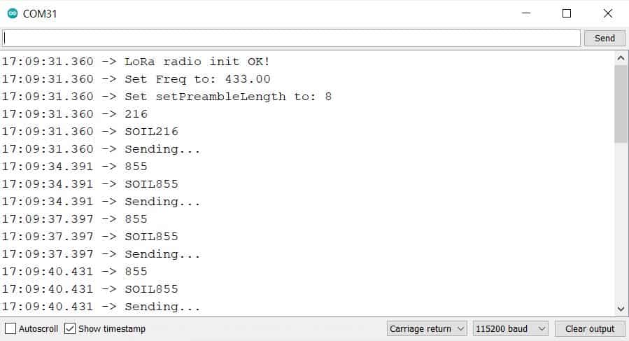
After uploading the code, you can open the Serial Monitor. The Serial Monitor will display the following message along with the analog value of Soil Moisture Sensor.
Setting up Loara Gateway Receiver Part
We use MicroPython for the LoRa Gateway Part. If you want to learn how to use MicroPython with ESP32, then you can following our ESP32 MicroPython Guide.
1. Plug the ESP32 and Lora extension boards together.
2. Connect MakePython ESP32 to your PC, open uPyCraft, and select Connect to the serial port.
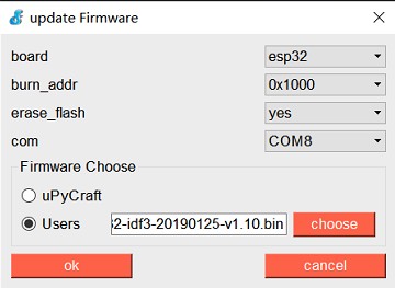
3. The firmware will be prompted if it has not been burned before. Do the following selection from the list. For firmware check the ESP32 Bin File
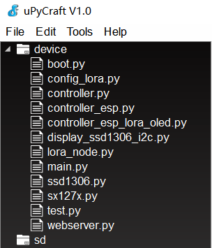
4. Download all python programs ending in.py from the LoraS2G/workSpace/ Folder to ESP32.
5. Press the RST button on ESP32 to reset the development board. The serial monitor displays the boot self-check information. If all goes well, the serial port will have a log of the wifi connection and display it on the ESP32’S LCD screen.
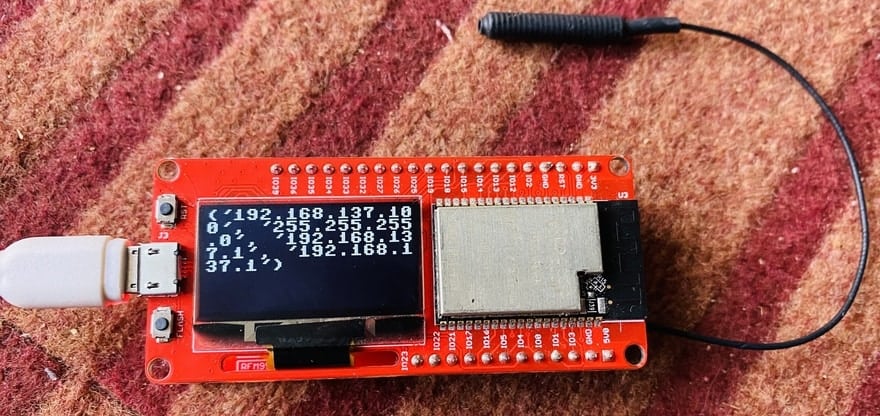
6. The first IP is the IP address that the node connects to WiFi. Open the browser and enter the first IP in the address bar and hit enter.
You can refresh the page after every 5 seconds. The sensor receives and uploads the data to WebServer after the interval of every 5 seconds.
MicroPython Code Explanation
1 controller.py
The Controller class is the parent class that abstracts the basic pin content of the Lora module.
Add_transceiver () adds an SX127X chip object as the sending chip because the MakePython Lora can carry two SX127X chips.
The remaining functions are some of the early test functions, or hardware pin preparation functions, of no concern to this experiment.
2 controller_esp.py
Machine module of MicroPyton is referenced to prepare SPI and GPIO initialization.
The Controller_esp is the Controller class inherits from the controller.
The model and SPI pins of the hardware for ESP were determined.
The rest of the overloaded member functions are initialized by hardware pins such as SPI.
3 controller_esp_lora_oled.py
controller_esp_lora_oled.Controller class inherits from the controller_esp.Controller。
The Controller_ESP_lora_OLd.Controller class inherits from the Controller_esp.Controller.
4 ssd1306.py
Ssd1306 led screen driver.
5 display_ssd1306_i2c.py
Ssd1306 LED screen based on I2C basic display library.
Text display function.
Image display function.
6 sx127x.py
Lora module driver function.
Includes basic Lora module Settings such as frequency, lead code, calibration, spread spectrum factor, etc.
7 config_lora.py
To accommodate some configuration code for multiple platforms.
8 lora_node.py
Lora Gateway object.
Encapsulated send method and receive interrupt and other functional functions.
Video Tutorial


2 Comments
can I buy this project
Great project, but I have run into a problem with the sensor node. It does not read the capacitance and only returns 0, even when put into water.
10:48:06.399 -> LoRa radio init OK!
10:48:06.399 -> Set Freq to: 915.00
10:48:06.399 -> Set setPreambleLength to: 8
10:48:06.399 -> 0
10:48:06.399 -> SOIL0
10:48:06.399 -> Sending…
10:48:11.377 -> 0
10:48:11.377 -> SOIL0
10:48:11.377 -> Sending…
10:48:16.417 -> 0
10:48:16.417 -> SOIL0
10:48:16.417 -> Sending…
The SENSOR_PIN is set to A2
Any suggestions