

Overview: IoT Based Battery Monitoring System using ESP8266
In this project, we will build an IoT based Battery Monitoring System using ESP8266 where you can monitor the battery charging/discharging status along with Battery Voltage & Percentage.
As we know, the battery is the most important component for any device as it powers the entire system. So, it is important to monitor the voltage level of the battery as improper or excess charging/discharging may lead to damage to the Battery or System Failure. Most of the electrical/electronics devices has a separate system called Battery Management System (BMS). The BMS monitors all the properties of the battery like the voltage, current, temperature & auto cut-off system. This ensures the safety and proper handling of Lithium-Ion or Lithium Polymer batteries.
Earlier BMS only monitors the condition of the battery and alarms the user via a battery indicator. But now due to the use of the Internet of Things, we can directly notify the users remotely. They can check the battery status on their smartphones or Computer dashboards from anywhere in the world.
In this IoT-based Battery Monitoring System, we will use Wemos D1 Mini with ESP8266 Chip to send the battery status data to ThingSpeak cloud. The Thingspeak will display the battery voltage along with the battery percentage in both the charging and discharging cases. A very precise version of this project can be checked at DIY LiPo Charger with IoT Battery Voltage Monitor, as this contains a customized PCB baord. In case you wanna monitor a Lead-Acid Battery, you can check 12V Battery Monitoring System project.
Bill of Materials
You will need the following components for the IoT Based Battery Monitoring System Project. You can purchase all the components online from Amazon.
| S.N. | Components | Quantity | Purchase Links |
|---|---|---|---|
| 2 | NodeMCU ESP8266 or Wemos D1 Mini Board | 1 | Amazon | AliExpress |
| 3 | TP4056 Battery Charging Module | 1 | Amazon | AliExpress |
| 4 | Resistor 100K | 2 | Amazon | AliExpress |
| 5 | Micro-USB Cable | 2 | Amazon | AliExpress |
| 6 | 3.7V Li-ion Battery | 1 | Amazon | AliExpress |
Lithium-Ion Batteries
A lithium-ion battery or Li-ion battery is a type of rechargeable battery. Lithium-ion batteries are commonly used for portable electronics and electric vehicles.

In this battery, lithium ions move from the negative electrode through an electrolyte to the positive electrode during discharge, and back when charging. Li-ion batteries use an intercalated lithium compound as the material at the positive electrode and typically graphite at the negative electrode. The batteries have a high energy density, no memory effect and low self-discharge.
Nominal, Maximum & Cut-off Voltage
I’ve been using several Lithium-Ion batteries for quite some time across multiple projects. Some of these batteries come with an attached Battery Management System Circuit, providing over-voltage protection, balanced charging, and short-circuit protection.
Typically, Lithium-Ion batteries have a nominal voltage of 3.7V. When fully charged, their maximum voltage can reach up to 4.2±0.5V. Manufacturer datasheets usually state the cut-off voltage to be around 3V, though this can vary based on the battery type and its specific applications. The battery I frequently use has a discharge cut-off voltage of 2.8V. However, there are also batteries available with a cut-off voltage as low as 2.5V.
Circuit & Schematic Designing
We will design a system to monitor this battery voltage along with charging and discharging status. For the microcontroller, we use Wemos D1 Mini which has an ESP8266 wifi-enabled chip. You can also use the NodeMCU ESP8266 Board. This WiFi chip can connect to the WiFi network and uploads the data regularly to the server.

You can use the TP4056 module to charge the battery as its best suited for Battery Management Applications. The MCP73831 IC can also be used instead of TP4056.
The ESP8266 Chip can only support the input analog voltage of 3.3V. But Battery voltage goes up to 4.2V. Hence we have to form a voltage divider network to lower down the input voltage.
Voltage Divider Network Calculations
The Battery Maximum voltage is 4.2V and the cut of voltage is 2.8V. Anything lesser than 3.3V will be easily supported by ESP8266 Analog Pin.
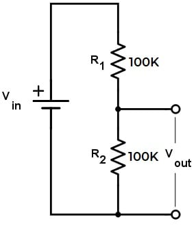
We have to first step down the upper voltage level. The source voltage is 4.2V and there is a pair of 100K resistors. This will give an output of 2.1V. Similarly, the minimum voltage is 2.8V as a cutoff voltage which steps down to 1.4V using the same voltage divider network. Hence, both the upper and lower voltage is supported by ESP8266 Analog Pin.
Here is a complete assembly of the project. This is the same connection as shown in the circuit diagram. For testing, you can use a Lithium-Ion Battery of any capacity. For example, I am using a Battery with a capacity 1950mAh.

Setting up Thingspeak
In order to Monitor the Battery Data on Thingspeak Server, you first need to Setup the Thingspeak. To set up the Thingspeak Server, visit https://thingspeak.com/. Create an account or simply sign in if you created the account earlier. Then create a new channel with following details.
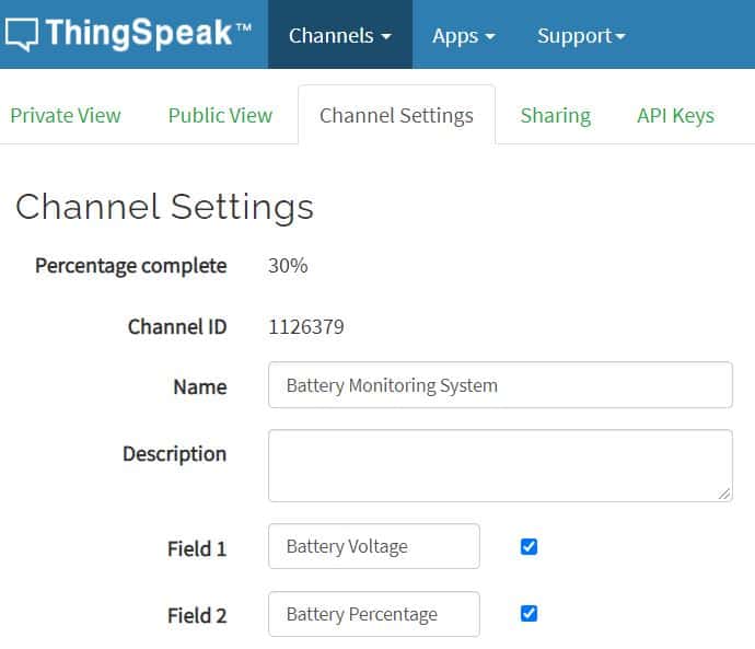
Then go to the API section of the dashboard and copy the API Key. This API key is needed in the code part.

Source Code/Program
Here is the source code for IoT Based Battery Status Monitoring System using ESP8266. Replace the WiFi SSID, Password and API Key in the code.
|
1 2 3 |
String apiKey = "**************"; // Enter your Thingspeak API Key const char* ssid = "**************"; // Enter your WiFi Network's SSID const char* pass = "**************"; // Enter your WiFi Network's Password |
Now copy the following code and upload it to your NodeMCU or Wemos D1 Mini Board.
|
1 2 3 4 5 6 7 8 9 10 11 12 13 14 15 16 17 18 19 20 21 22 23 24 25 26 27 28 29 30 31 32 33 34 35 36 37 38 39 40 41 42 43 44 45 46 47 48 49 50 51 52 53 54 55 56 57 58 59 60 61 62 63 64 65 66 67 68 69 70 71 72 73 74 75 76 77 78 79 80 81 82 83 84 85 86 87 88 89 90 91 92 |
#include <ESP8266WiFi.h> String apiKey = "**************"; const char* ssid = "**************"; // Enter your WiFi Network's SSID const char* pass = "**************"; // Enter your WiFi Network's Password const char* server = "api.thingspeak.com"; int analogInPin = A0; // Analog input pin int sensorValue; // Analog Output of Sensor float calibration = 0.36; // Check Battery voltage using multimeter & add/subtract the value int bat_percentage; WiFiClient client; void setup() { Serial.begin(115200); Serial.println("Connecting to "); Serial.println(ssid); WiFi.begin(ssid, pass); while (WiFi.status() != WL_CONNECTED) { delay(100); Serial.print("*"); } Serial.println(""); Serial.println("WiFi connected"); } void loop() { sensorValue = analogRead(analogInPin); float voltage = (((sensorValue * 3.3) / 1024) * 2 + calibration); //multiply by two as voltage divider network is 100K & 100K Resistor bat_percentage = mapfloat(voltage, 2.8, 4.2, 0, 100); //2.8V as Battery Cut off Voltage & 4.2V as Maximum Voltage if (bat_percentage >= 100) { bat_percentage = 100; } if (bat_percentage <= 0) { bat_percentage = 1; } Serial.print("Analog Value = "); Serial.print(sensorValue); Serial.print("\t Output Voltage = "); Serial.print(voltage); Serial.print("\t Battery Percentage = "); Serial.println(bat_percentage); delay(1000); if (client.connect(server, 80)) { String postStr = apiKey; postStr += "&field1="; postStr += String(voltage); postStr += "&field2="; postStr += String(bat_percentage); postStr += "\r\n\r\n"; client.print("POST /update HTTP/1.1\n"); delay(100); client.print("Host: api.thingspeak.com\n"); delay(100); client.print("Connection: close\n"); delay(100); client.print("X-THINGSPEAKAPIKEY: " + apiKey + "\n"); delay(100); client.print("Content-Type: application/x-www-form-urlencoded\n"); delay(100); client.print("Content-Length: "); delay(100); client.print(postStr.length()); delay(100); client.print("\n\n"); delay(100); client.print(postStr); delay(100); } client.stop(); Serial.println("Sending...."); delay(15000); } float mapfloat(float x, float in_min, float in_max, float out_min, float out_max) { return (x - in_min) * (out_max - out_min) / (in_max - in_min) + out_min; } |
IoT Based Battery Monitoring System using ESP8266 on Thingspeak
Open the Serial Monitor after uploading the code. The ESP8266 will try connecting to the WiFi Network. Once it connects to the WiFi Network, it will display the Analog Value along with Battery Voltage & Percentage.

Then go to the private view of Thingspeak Dashboard. The Battery Voltage and Battery Percentage will fill the graph. The graph will rise up when the device is charging and will go down when it’s discharging.

Fixing Voltage Value and Calibration
The circuit is designed to fix 100K pair of resistors. But most of the resistors have a tolerance of ±5%. Because of this resistor values may be between 95K to 105K. As a result, the output voltage and the analog signal output both are affected.
In order to fix this issue, you can compare the voltage difference between the Serial Monitor reading and Multimeter reading. Read the output voltage value at the TP4056 output terminal using a multimeter.

Subtract the Multimeter voltage value from the value obtained on Serial Monitor.
In the following line of the code add this calibration factor.
|
1 |
float calibration = 0.36; // Check Battery voltage using multimeter & add/subtract the value |
This will fix any error in the voltage reading. So this is how we can design IoT Based Battery Status Monitoring System using ESP8266 and get the reading on Thingspeak Server.
Incase you want an accurate battery status monitoring device, they you can use MAX17043 fule gauge IC which removes all the limiatations of measuring battery percentage by this method.
Video Tutorial & Guide: IoT Based Battery Monitoring System

If you want to monitor the Solar power using the same Thingspeak Server, you may refer to Solar Power Monitoring System project for managing the Solar Panel.
 & Live Dashboard")


5 Comments
In your voltage divider calculation you seem to ignore the fact the Wemos has an onboard voltage divider
Its Good turorial, thank you for sharing,
In this prroject you are using 3.7V and 500 MAh Battery…!, can we use same method(circuit and code) for 8000 MAh
and 3.7 V battery?
it shouldnt really matter since youre measuring voltage not mAh/Wh
I wish in these type of examples, you wouldn’t overcomplicate it by adding in an aspect like ThingSpeak. It just makes the resulting code harder to understand for newbies and adds another level of complexity. Just Serial Print it and let us format the data how we will!
I have built this project, but find the readings to be wildly incorrect when you look at lower of higher voltages than the one you calibrate it for (12 volt) 10 volts then reads 7 volts.14 volts reads 16 volts. Can you advise of a fix to make it more accurate. Thanks.