

Overview: IoT Based Heart Rate Monitor using ESP8266 & Arduino
In this project, we will make IoT Based Heart Rate Monitor using NodeMCU ESP8266, Arduino & Easy Pulse Sensor. We will display the value of Pulse Rate or BPM on OLED Display as well as MQTT Dashboard simultaneously. In one of the previous project, we use Optical Pulse Sensor with NodeMCU ESP8266 that can connect to the Wifi Network and uploads the Heart Rate (BPM) Value to Thingspeak Server regularly.
The free version of Thingspeak Server has limited access. The data uploads to Thingspeak Server only after an interval of 15 seconds. This is why it is necessary to select the method that can easily suit our requirements. MQTT protocol fulfills our requirements. MQTT is a lightweight publish/subscribe messaging protocol designed for low-bandwidth, high latency, unreliable networks. MQTT’s features make it an excellent option for sending high volumes of sensor messages to analytics platforms and cloud solutions.
So, one of the best MQTT platforms for IoT Project is Ubidots. We can use the Ubidots platform to send data to the cloud from any Internet-enabled device. In this IoT MQTT Based Heart Rate Monitor Project, we will interface the Easy Pulse Sensor with Arduino & ESP8266. We will first display the Pulse Rate Data on OLED Display. Then using the WiFi connectivity, the data will be sent to the Ubidtos MQTT Cloud.
Bill of Materials
Following are the list of components and modules that you need for this project. You can purchase all the components online from Amazon from the given purchase link.
| S.N. | Components | Quantity | Purchase Links |
|---|---|---|---|
| 1 | Arduino Nano Board | 1 | Amazon | AliExpress |
| 2 | NodeMCU ESP8266 Board | 1 | Amazon | AliExpress |
| 3 | Easy Pulse Sensor HRM-2511-E | 1 | Graylogix |
| 4 | 0.96" I2C OLED Display | 1 | Amazon | AliExpress |
| 5 | 5V DC Power Supply | 1 | Amazon | AliExpress |
| 6 | Connecting Wires | 10 | Amazon | AliExpress |
| 7 | Breadboard | 1 | Amazon | AliExpress |
Easy Pulse Sensor
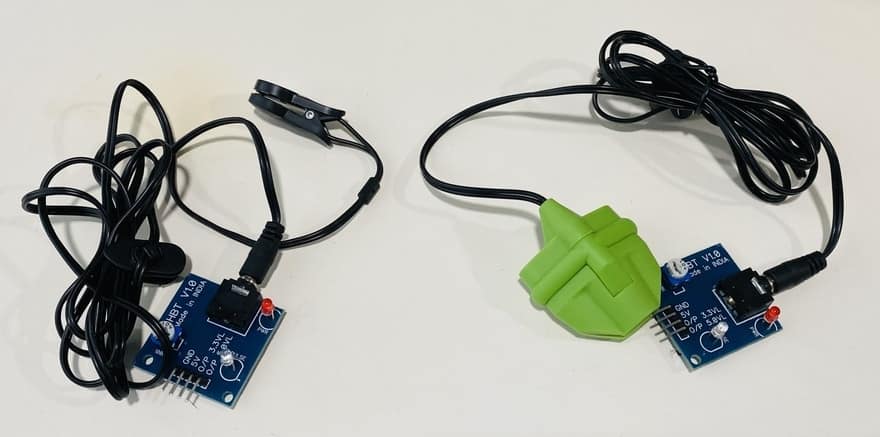
The Easy Pulse Sensor is a DIY pulse sensor that is designed for hobbyists and educational applications. It is used to illustrate the principle of photoplethysmography (PPG). PPG is a non-invasive technique for detecting the cardio-vascular pulse wave from a fingertip. The Easy Pulse Sensor uses a transmission mode PPG probe (HRM-2511E) sensor.

The Sensor uses an infrared light source to illuminate the finger on one side. On the other side of the sensor, there is a photodetector that measures small variations in the transmitted light intensity due to changes in blood volume inside the tissue. The onboard components & instrumentation provide a clean and filtered analog PPG waveform. The on-board LED also indicates the digital pulse output. The analog and digital signals are both synchronous with the heartbeat.

Earlier, we used the Easy Pulse Sensor with Arduino to display the BPM Value on OLED Display. You can check the post here: Arduino Easy Pulse Sensor Tutorial
Block Diagram: IoT Based Heart Rate Monitor using ESP8266 Arduino on MQTT
For easy and clear understanding let us go through the block diagram. This is a simple diagramatic demonstration of the project: IoT Based Heart Rate Monitor using ESP8266 Arduino & Pulse Sensor.

We first Connect the Pulse Sensor to Arduino. Using UART Communication, we send the data from Arduino to NodeMCU ESP8266. We could have directly connected the Pulse Sensor to NodeMCU ESP8266 Board. But the pulse sensor doesn’t seem working and giving any output on Serial Monitor. So it’s easy to use the UART method to retrieve the data from Arduino to ESP8266.
The NodeMCU ESP8266 connects to the WiFi Network. It then uploads or publishes the BPM topic to MQTT Cloud Called Ubidots. The published data can be viewed on Computer or Mobile phones using the Ubidots Dashboard as they are the subscriber. This is how the entire IoT Based Heart Rate Monitor Project works.
Circuit Diagram & Connections
You can convert the above block diagram to the circuit diagram. I use Fritzing to draw the schematics. The connetion between Pulse Sensor ESP8266 & Arduino is fairly simple.

We use Software Serial Method to communicate between ESP8266 & Arduino. For that connect the TX & RX Pins of ESP8266 to Arduino digital 7 & 8 Pins. Connect the input of the pulse sensor to Arduino A0 Pin. Similarly, connect the Pulse Sensor VCC & GND Pin to 5V & GND of Arduino.
As OLED Display is an I2C Module, so connect its I2C Pin, i.e SDA & SCL to D2 & D1 of NodeMCU respectively. Also connect the VCC & GND Pin of OLED Display to 3.3V & GND of ESP8266.

Setting Up Ubidots
We need to setup the Ubidots dashboard in order to recieve the Pulse Sensor BPM data from ESP8266 MQTT. In order to set up Ubidots, visit https://ubidots.com/ & create a New Account using your email address.

After login into Ubidots Dashboard, we need an API Key. To get the API key, click on the top right of the dashboard on the profile option. You will see an option called “API Credentials”. Click on the option.

Now when you click on Default Token and copy the API Token. You need an API Token in the code part to receive the data.

Source Code/program
The code for IoT Based Heart Rate Monitor using ESP8266 & Arduino on MQTT is divided into two part. We have to write and upload the program for both Arduino & NodeMCU Board.
But before that, there are few libraries that are required for project compilation. Check all of these libraries below and add it to the Arduino Library Folder.
- Pulse Sensor Library: Download
-
ESP8266 MQTT Ubidots Library: Download
-
PubSubClient Library: Download
-
Adafruit GFX Library: Download
-
Adafruit SSD1306 Library: Download
Code for Arduino Board
|
1 2 3 4 5 6 7 8 9 10 11 12 13 14 15 16 17 18 19 20 21 22 23 24 25 26 27 28 29 30 31 32 33 34 35 36 37 38 39 40 41 42 43 44 45 46 47 48 49 |
#include <SoftwareSerial.h> #define USE_ARDUINO_INTERRUPTS true // Set-up low-level interrupts for most acurate BPM math #include <PulseSensorPlayground.h> // Includes the PulseSensorPlayground Library SoftwareSerial nodemcu(7, 8); // nodemcu module connected here const int PulseWire = 0; // 'S' Signal pin connected to A0 const int LED13 = 13; // The on-board Arduino LED int Threshold = 550; // Determine which Signal to "count as a beat" and which to ignore String myString; String cmessage; // complete message char buff[10]; PulseSensorPlayground pulseSensor; // Creates an object void setup() { Serial.begin(9600); nodemcu.begin(9600); // Configure the PulseSensor object, by assigning our variables to it pulseSensor.analogInput(PulseWire); pulseSensor.blinkOnPulse(LED13); // Blink on-board LED with heartbeat pulseSensor.setThreshold(Threshold); // Double-check the "pulseSensor" object was created and began seeing a signal if (pulseSensor.begin()) { Serial.println("PulseSensor object created!"); } } void loop() { int myBPM = pulseSensor.getBeatsPerMinute(); // Calculates BPM if (pulseSensor.sawStartOfBeat()) // Constantly test to see if a beat happened { Serial.println("♥ A HeartBeat Happened ! "); // If true, print a message Serial.print("BPM: "); Serial.println(myBPM); // Print the BPM value myString = dtostrf(myBPM, 3, 0, buff); cmessage = cmessage + myString ; nodemcu.println(cmessage); Serial.println(cmessage); cmessage = ""; Serial.println(); } delay(20); } |
Code for NodeMCU ESP8266 Board
From this code, change the WiFi SSID, Password & Ubidots Token.
|
1 2 3 4 5 6 7 8 9 10 11 12 13 14 15 16 17 18 19 20 21 22 23 24 25 26 27 28 29 30 31 32 33 34 35 36 37 38 39 40 41 42 43 44 45 46 47 48 49 50 51 52 53 54 55 56 57 58 59 60 61 62 63 64 65 66 67 68 69 70 71 72 73 74 75 76 77 78 79 80 81 82 83 84 85 86 87 88 89 90 91 92 93 94 95 96 97 98 99 100 |
#include <Wire.h> #include <SPI.h> #include <Adafruit_GFX.h> #include <Adafruit_SSD1306.h> #include "UbidotsESPMQTT.h" #include <SoftwareSerial.h> String myString; // complete message from arduino, which consistors of snesors data char rdata; // received charactors String myBPM; #define TOKEN "******************" // Your Ubidots TOKEN #define WIFINAME "******************" //Your SSID #define WIFIPASS "******************" // Your Wifi Pass #define SCREEN_WIDTH 128 // OLED display width, in pixels #define SCREEN_HEIGHT 64 // OLED display height, in pixels #define OLED_RESET -1 // Reset pin # (or -1 if sharing Arduino reset pin) Adafruit_SSD1306 display(SCREEN_WIDTH, SCREEN_HEIGHT, &Wire, OLED_RESET); Ubidots client(TOKEN); void callback(char* topic, byte* payload, unsigned int length) { Serial.print("Message arrived ["); Serial.print(topic); Serial.print("] "); for (int i = 0; i < length; i++) { Serial.print((char)payload[i]); } Serial.println(); } void setup() { client.setDebug(true); // Pass a true or false bool value to activate debug messages Serial.begin(9600); if (!display.begin(SSD1306_SWITCHCAPVCC, 0x3C)) { Serial.println(F("SSD1306 allocation failed")); for (;;); // Don't proceed, loop forever } display.display(); delay(100); display.clearDisplay(); client.wifiConnection(WIFINAME, WIFIPASS); client.begin(callback); } void loop() { if (Serial.available() > 0 ) { rdata = Serial.read(); myString = myString + rdata; if ( rdata == '\n') { Serial.println(myString); myBPM = getValue(myString, ',', 0); myString = ""; } if (!client.connected()) { client.reconnect(); } int BPMvalue = myBPM.toInt(); client.add("BPM", BPMvalue); client.ubidotsPublish("ESP8266"); client.loop(); Serial.println(); delay(100); } display.clearDisplay(); display.setTextSize(2); display.setTextColor(WHITE); display.setCursor(10, 30); display.print("BPM"); //display.setCursor(5, 40); display.print(myBPM); display.display(); } String getValue(String data, char separator, int index) { int found = 0; int strIndex[] = { 0, -1 }; int maxIndex = data.length() - 1; for (int i = 0; i <= maxIndex && found <= index; i++) { if (data.charAt(i) == separator || i == maxIndex) { found++; strIndex[0] = strIndex[1] + 1; strIndex[1] = (i == maxIndex) ? i + 1 : i; } } return found > index ? data.substring(strIndex[0], strIndex[1]) : ""; } |
Monitoring the Pulse Rate (BPM) Value on OLED & Cloud
Upload the code to the Arduino & NodeMCU Board. After uploading the code, attach the Probe to Finger or if you are using Earlobe clip attach it to ear.

Open the Serial Monitor on Arduino Code Part. Then you will see the Pulse Rate or BPM Value on Serial Monitor.
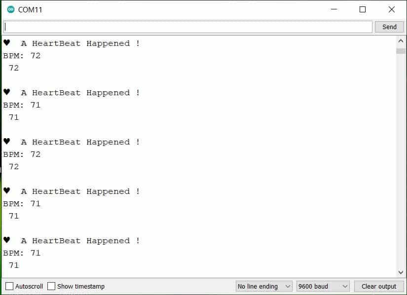
Also open the tab Serial Monitor for NodeMCU ESP8266 Output. You will see data being received via UART of Arduino. The data publish log will also be displayed on Serial Monitor.

Apart from the Serial Monitor, you can see the BPM value on OLED Display as well. In case if you don’t want this project with MQTT Connection, then you can use OLED to monitor the Heart Rate data.

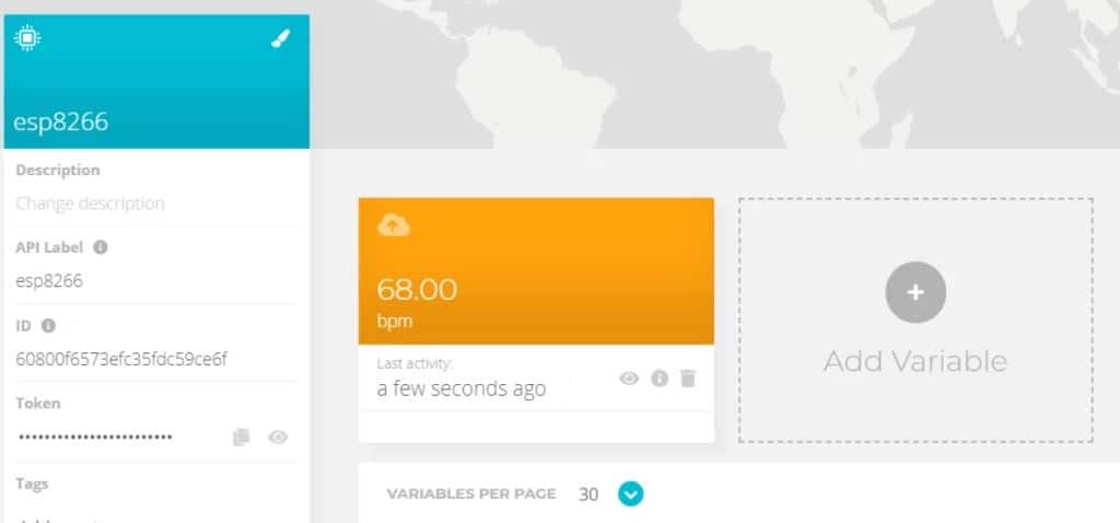
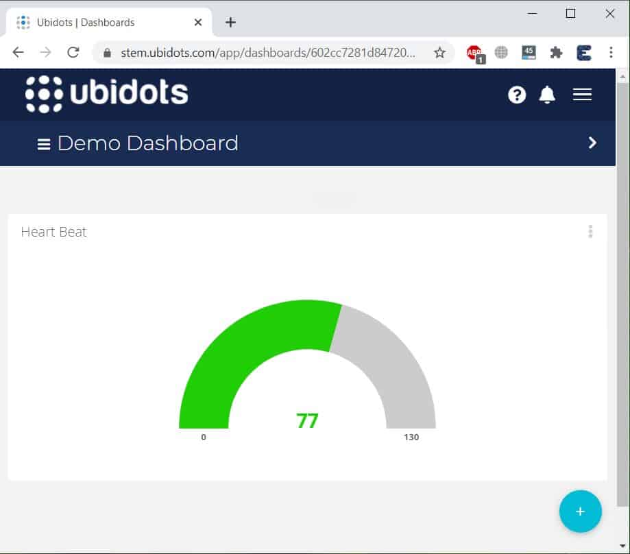
To check the data online from any part of the world, you can visit the Ubidots Dashboard.
The data get logged after regular intervals. You can check all the logged data in table format as well.
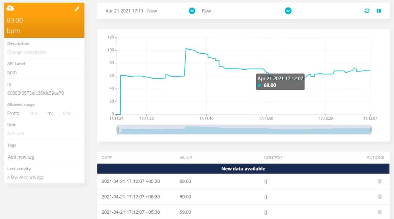
You can create your own widgets from the dashboard. The widgets make the dashboard more beautiful.
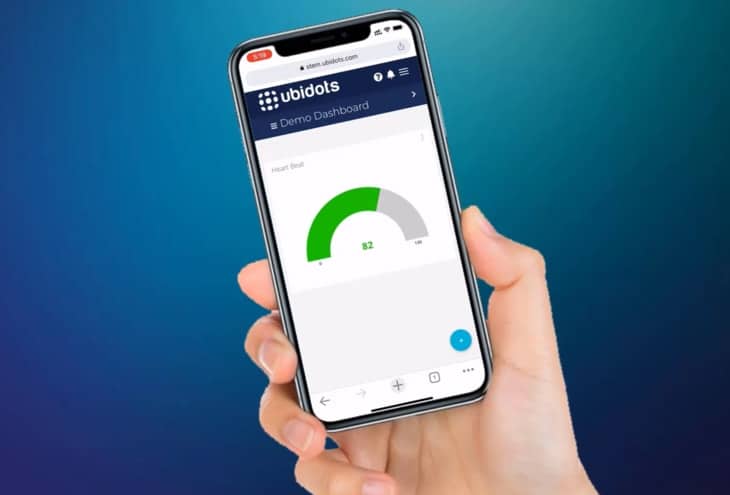
The online monitoring of Heart Rate Data is not only limited to the Computer dashboard. But you can also check it on the mobile dashboard.
Video Tutorial & Guide


1 Comment
How to Interface Pulse Sensor with ESP8266 using Arduino Programming