

Overview
In this tutorial, we will make Ultrasonic Range Finder with ESP32 TFT Display & HC-SR04 Ultrasonic Sensor. The project uses an embedded board that combines a 3.5” touchscreen display and ESP32-WROVER Module with a built-in 2M pixel OV2640 camera. We will connect the HC-SR04 Ultrasonic Sensor externally to the digital pins of ESP32.
The HC-SR04 ultrasonic sensor uses SONAR to determine the distance of an object just like the bats do. It offers excellent non-contact range detection with high accuracy and stable readings in an easy-to-use package from 2 cm to 400 cm or 1” to 13 feet. The 3.5″ TFT Touch Screen Display uses an ILI9488 TFT LCD Driver. The screen resolution is 320×480. There are multiple external pins to connect the ESP32 display with sensors/actuators. This is the reason they are suitable for various IoT applications.
We will now see how we can use the ESP32 TFT Display along with the Ultrasonic Sensor to create a beautiful dynamic analog type display. The ESP32 Ultrasonic Range Finder will display the distance in cm on TFT Touch Display.
Bill of Materials
Following are the list of components that you need for making this project. You can purchase all these components online.
| S.N. | Components | Quantity | Purchase Link |
|---|---|---|---|
| 1 | ESP32+TFT Touch Display | 1 | Makerfabs Link |
| 2 | Ultrasonic Sensor HC-SR04 | 1 | Amazon | AliExpress |
| 3 | Type C USB Cable | 1 | Amazon | AliExpress |
| 3 | Connecting Wires | 3 | Amazon | AliExpress |
ESP32 3.5″ TFT Touch(Capacitive) with Camera
This is a beautiful 3.5” touchscreen display, based on ESP32-WROVER chip, with a built-in 2M pixel OV2640 camera. The combination of all these gives a perfect platform for multiple ESP32 Applications & Projects.

The TFT LCD driver is basically ILI9488 & has a dimension of 3.5″ with 320×480 screen resolution. The ILI9488 LCD uses SPI for communication with the ESP32 chip. The SPI main clock could be up to 60M~80M, make the display smooth enough for videos.
While the camera is not used, you can freely use all these pins with the breakout connectors. You can then connect the ESP32 display with sensors or modules & use it for any IoT applications. The ESP32 chip support Arduino or MicroPython programming
The board is having a micro SD-Card slot for attaching an external SD-Card. The SD Card can be used for storing files and images. There is a type C USB Port, basically a USB to UART converter for ESP32 programming. You can connect a Type-C data cable to the board & directly upload the code to the Board.

Specification
1. 3.5 inch display, 320×480
2. Capacitive/Resistive Touch
3. ESP32-WROVER Controller
4. WIFI/ BLE Connection.
5. Onboard USB2UART convertor for ESP32 programming
6. 2M pixel OV2640 Camera
7. OV2640 supports output images up to 2 million pixels
8. LCD 3.5-inch Amorphous-TFT-LCD for mobile-phone or handy electrical equipment
9. LCD Driver: ILI9488
10. LCD Resolution: 320*480
11. Micro SD card slot on the board
12. NS2009: A 4-wire resistive touch screen control circuit
13. FT6236: single-chip capacitive touch panel controller Integrated Circuit
14. Power supply: 5V, Type-C USB
Check some of our previous projects using this TFT Touch Screen Display:
1. ESP32 TFT Touch Display Video Games
2. ESP32 TFT Touch & Camera Projects
HC-SR04 Ultrasonic Sensor
The HC-SR04 ultrasonic sensor uses sonar to determine the distance to an object like bats do. It offers excellent non-contact range detection with high accuracy and stable readings in an easy-to-use package.

The module can measure the distance from 2cm to 400 cm or 1” to 13 feet. Its operation is not affected by sunlight or black material like sharp rangefinders are (although acoustically soft materials like cloth can be difficult to detect). It comes complete with the ultrasonic transmitter and a receiver module.
Specifications:
- Minimum measuring range – 2 cm
- Maximum measuring range : 400 cm or 4 meter
- Accuracy : 3 mm
- Operating Voltage : +5V
- Operating Current : 15mA
- Working Frequency : 40 KHz
- Trigger Input signal : 10us pulse
- Measuring angle : 15 degree
Pins:
- VCC: +5VDC
- Trig : Trigger (INPUT)
- Echo: Echo (OUTPUT)
- GND: GND
How Does it Work?
Ultrasonic sensors emit short, high-frequency sound pulses at regular intervals. These propagate in the air at the velocity of sound. If they strike an object, then they are reflected back as echo signals to the sensor, which itself computes the distance to the target based on the time span between emitting the signal and receiving the echo.

We have to convert this time into cm to calculate the distance traveled. We will use the following equation to calculate the distance.
S = v * t
The ultrasonic wave is basically a sound wave that travels at a speed of 340 m/s (0.034 cm/s). The ultrasonic sensor is measuring the time it takes to hit the object and then come back but we need only the time that it takes to hit the object. So, we will divide it by 2.
S = (t * 0.034)/2
To learn more in detail about this sensor, check our previous post related to HC-SR04 Ultrasonic Sensor: HC-SR04 Arduino Guide.
Hardware Connections for ESP32 TFT Display with HC-SR04 Ultrasonic Sensor
To make an Ultrasonic Range Finder using ESP32 & HC-SR04 Sensor, we need following connections. As TFT Touch Display and ESP32-Wrover Module are internally connected to the PCB, we only require Ultrasonic Sensor Connection. Connect the HC-SR04 Sensor as per the diagram below.

Connect the VCC and GND Pin of HC-SR04 Sensor to 3.3V & GND Pin of ESP32. Similarly, connect its echo and trig pin to GPIO26 & GPIO27 of ESP32 respectively.
Adding Necessary Libraries to Arduino IDE
1. TFT_eSPI Library
This is a TFT graphics library for Arduino processors with performance optimization for STM32, ESP8266 & ESP32. The library is targeted at 32-bit processors. It supports “Four wire” SPI and 8 bit parallel interfaces. The library supports some TFT displays with drivers for ILI9163, ILI9225, ILI9341, ILI9488, ST7735 etc.
You can download the library from the Github directory. But the library requires some modification for our project. So here is an edited version of the library. You can download and add it to the library folder.
Download: TFT_eSPI Library
2. Simple HCSR04 Library
This is a simple library for Ultrasonic Sensor HC-SR04. You can use the method with multiple sensors by creating multiple Simple_HCSR04 Objects.
Download: Simple HCSR04 Library
Source Code/program
|
1 2 3 4 5 6 7 8 9 10 11 12 13 14 15 16 17 18 19 20 21 22 23 24 25 26 27 28 29 30 31 32 33 34 35 36 37 38 39 40 41 42 43 44 45 46 47 48 49 50 51 52 53 54 55 56 57 58 59 60 61 62 63 64 65 66 67 68 69 70 71 72 73 74 75 76 77 78 79 80 81 82 83 84 85 86 87 88 89 90 91 92 93 94 95 96 97 98 99 100 101 102 103 104 105 106 107 108 109 110 111 112 113 114 115 116 117 118 119 120 121 122 123 124 125 126 127 128 129 130 131 132 133 134 135 136 137 138 139 140 141 142 143 144 145 146 147 148 149 150 151 152 153 154 155 156 157 158 159 160 161 162 163 164 165 166 167 168 169 170 171 172 173 174 175 176 177 178 179 180 181 182 183 184 185 186 187 188 189 190 191 192 193 194 195 196 197 198 199 200 201 202 203 204 205 206 207 208 209 210 211 212 213 214 215 216 217 218 219 220 221 222 223 224 225 226 227 228 |
#include <SPI.h> #include <Simple_HCSR04.h> #include <TFT_eSPI.h> // Hardware-specific library #include <Arduino.h> #define ECHO_PIN 26 /// the pin at which the sensor echo is connected #define TRIG_PIN 27 /// the pin at which the sensor trig is connected // Define meter size as multiplier of 240 pixels wide 1.0 and 1.3333 work OK #define M_SIZE 2.05 Simple_HCSR04 *sensor; TFT_eSPI tft = TFT_eSPI(); // Invoke custom library const char union_text[] = "cm"; #define TFT_GREY 0x5AEB float ltx = 0; // Saved x coord of bottom of needle uint16_t osx = M_SIZE * 120, osy = M_SIZE * 120; // Saved x & y coords uint32_t updateTime = 0; // time for next update int old_analog = -999; // Value last displayed int value[6] = {0, 0, 0, 0, 0, 0}; int old_value[6] = {-1, -1, -1, -1, -1, -1}; int d = 0; void setup(void) { Serial.begin(115200); // For debug sensor = new Simple_HCSR04(ECHO_PIN, TRIG_PIN); tft.init(); tft.setRotation(3); tft.fillScreen(TFT_BLACK); analogMeter(); // Draw analogue meter tft.setCursor(10, 300); tft.setTextSize(2); tft.println("Makerfabs Ultrasonic Ranging"); updateTime = millis(); // Next update time } void loop() { if (updateTime <= millis()) { unsigned long distance = sensor->measure()->cm(); Serial.print("distance: "); Serial.print(distance); Serial.print("cm\n"); updateTime = millis() + 35; // Update emter every 35 milliseconds plotNeedle(distance, 0); } } // ######################################################################### // Draw the analogue meter on the screen // ######################################################################### void analogMeter() { // Meter outline tft.fillRect(0, 0, M_SIZE * 239, M_SIZE * 126, TFT_GREY); tft.fillRect(5, 3, M_SIZE * 230, M_SIZE * 119, TFT_WHITE); tft.setTextColor(TFT_BLACK); // Text colour // Draw ticks every 5 degrees from -50 to +50 degrees (100 deg. FSD swing) for (int i = -50; i < 51; i += 5) { // Long scale tick length int tl = 15; // Coodinates of tick to draw float sx = cos((i - 90) * 0.0174532925); float sy = sin((i - 90) * 0.0174532925); uint16_t x0 = sx * (M_SIZE * 100 + tl) + M_SIZE * 120; uint16_t y0 = sy * (M_SIZE * 100 + tl) + M_SIZE * 140; uint16_t x1 = sx * M_SIZE * 100 + M_SIZE * 120; uint16_t y1 = sy * M_SIZE * 100 + M_SIZE * 140; // Coordinates of next tick for zone fill float sx2 = cos((i + 5 - 90) * 0.0174532925); float sy2 = sin((i + 5 - 90) * 0.0174532925); int x2 = sx2 * (M_SIZE * 100 + tl) + M_SIZE * 120; int y2 = sy2 * (M_SIZE * 100 + tl) + M_SIZE * 140; int x3 = sx2 * M_SIZE * 100 + M_SIZE * 120; int y3 = sy2 * M_SIZE * 100 + M_SIZE * 140; // Green zone limits if (i >= 0 && i < 25) { tft.fillTriangle(x0, y0, x1, y1, x2, y2, TFT_GREEN); tft.fillTriangle(x1, y1, x2, y2, x3, y3, TFT_GREEN); } // Orange zone limits if (i >= 25 && i < 50) { tft.fillTriangle(x0, y0, x1, y1, x2, y2, TFT_ORANGE); tft.fillTriangle(x1, y1, x2, y2, x3, y3, TFT_ORANGE); } // Short scale tick length if (i % 25 != 0) tl = 8; // Recalculate coords incase tick lenght changed x0 = sx * (M_SIZE * 100 + tl) + M_SIZE * 120; y0 = sy * (M_SIZE * 100 + tl) + M_SIZE * 140; x1 = sx * M_SIZE * 100 + M_SIZE * 120; y1 = sy * M_SIZE * 100 + M_SIZE * 140; // Draw tick tft.drawLine(x0, y0, x1, y1, TFT_BLACK); // Check if labels should be drawn, with position tweaks if (i % 25 == 0) { // Calculate label positions x0 = sx * (M_SIZE * 100 + tl + 10) + M_SIZE * 120; y0 = sy * (M_SIZE * 100 + tl + 10) + M_SIZE * 140; switch (i / 25) { case -2: tft.drawCentreString("0", x0, y0 - 12, 2); break; case -1: tft.drawCentreString("25", x0, y0 - 9, 2); break; case 0: tft.drawCentreString("50", x0, y0 - 7, 2); break; case 1: tft.drawCentreString("75", x0, y0 - 9, 2); break; case 2: tft.drawCentreString("100", x0, y0 - 12, 2); break; } } // Now draw the arc of the scale sx = cos((i + 5 - 90) * 0.0174532925); sy = sin((i + 5 - 90) * 0.0174532925); x0 = sx * M_SIZE * 100 + M_SIZE * 120; y0 = sy * M_SIZE * 100 + M_SIZE * 140; // Draw scale arc, don't draw the last part if (i < 50) tft.drawLine(x0, y0, x1, y1, TFT_BLACK); } tft.drawString(union_text, M_SIZE * (5 + 230 - 40), M_SIZE * (119 - 20), 2); // Units at bottom right tft.drawCentreString(union_text, M_SIZE * 120, M_SIZE * 70, 4); // Comment out to avoid font 4 tft.drawRect(5, 3, M_SIZE * 230, M_SIZE * 119, TFT_BLACK); // Draw bezel line plotNeedle(0, 0); // Put meter needle at 0 } // ######################################################################### // Update needle position // This function is blocking while needle moves, time depends on ms_delay // 10ms minimises needle flicker if text is drawn within needle sweep area // Smaller values OK if text not in sweep area, zero for instant movement but // does not look realistic... (note: 100 increments for full scale deflection) // ######################################################################### void plotNeedle(int value, byte ms_delay) { tft.setTextColor(TFT_BLACK, TFT_WHITE); char buf[8]; dtostrf(value, 4, 0, buf); tft.drawRightString(buf, M_SIZE * 40, M_SIZE * (119 - 20), 2); if (value < -10) value = -10; // Limit value to emulate needle end stops if (value > 110) value = 110; // Move the needle until new value reached while (!(value == old_analog)) { if (old_analog < value) old_analog++; else old_analog--; if (ms_delay == 0) old_analog = value; // Update immediately if delay is 0 float sdeg = map(old_analog, -10, 110, -150, -30); // Map value to angle // Calcualte tip of needle coords float sx = cos(sdeg * 0.0174532925); float sy = sin(sdeg * 0.0174532925); // Calculate x delta of needle start (does not start at pivot point) float tx = tan((sdeg + 90) * 0.0174532925); // Erase old needle image tft.drawLine(M_SIZE * (120 + 20 * ltx - 1), M_SIZE * (140 - 20), osx - 1, osy, TFT_WHITE); tft.drawLine(M_SIZE * (120 + 20 * ltx), M_SIZE * (140 - 20), osx, osy, TFT_WHITE); tft.drawLine(M_SIZE * (120 + 20 * ltx + 1), M_SIZE * (140 - 20), osx + 1, osy, TFT_WHITE); // Re-plot text under needle tft.setTextColor(TFT_BLACK); //tft.drawCentreString(union_text, M_SIZE * 120, M_SIZE * 70, 4); // // Comment out to avoid font 4 // Store new needle end coords for next erase ltx = tx; osx = M_SIZE * (sx * 98 + 120); osy = M_SIZE * (sy * 98 + 140); // Draw the needle in the new postion, magenta makes needle a bit bolder // draws 3 lines to thicken needle tft.drawLine(M_SIZE * (120 + 20 * ltx - 1), M_SIZE * (140 - 20), osx - 1, osy, TFT_RED); tft.drawLine(M_SIZE * (120 + 20 * ltx), M_SIZE * (140 - 20), osx, osy, TFT_MAGENTA); tft.drawLine(M_SIZE * (120 + 20 * ltx + 1), M_SIZE * (140 - 20), osx + 1, osy, TFT_RED); // Slow needle down slightly as it approaches new postion if (abs(old_analog - value) < 10) ms_delay += ms_delay / 5; // Wait before next update delay(ms_delay); } } |
From the tools menu select the ESP32 Wrover Module and following other options.

Connect the ESP32 Board with Type-C USB Cable and then upload the code.
Ultrasonic Range Finder with ESP32 TFT Display & HC-SR04
After uploading the code, the TFT Display will start showing the distance data with a Analog Type Circular needle display.
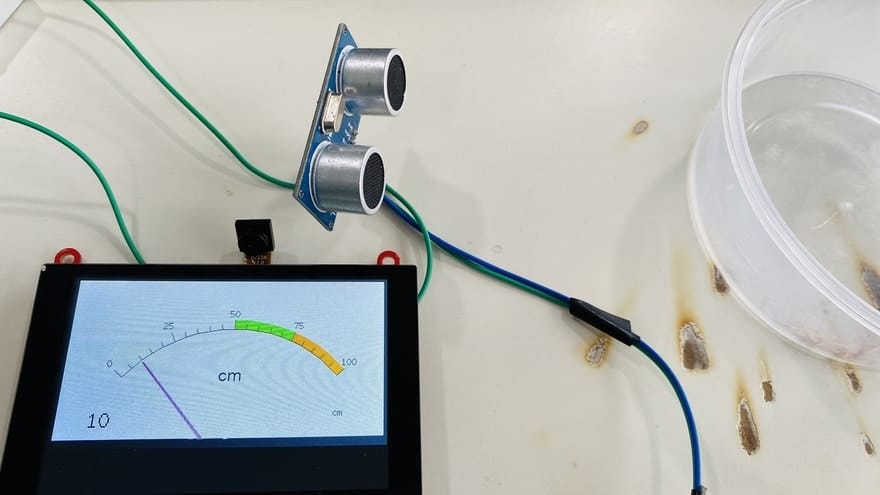
You can manually increase the distance from the sensor to check the change in the distance on TFT LCD Screen.
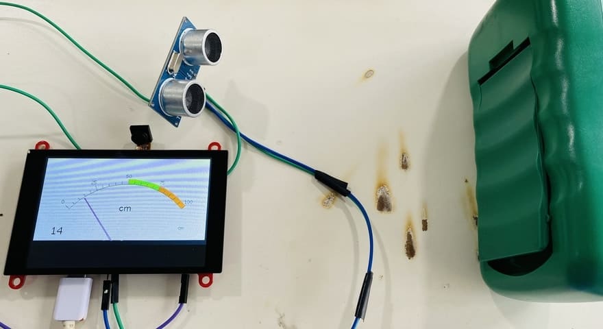
This is how you can make Ultrasonic Range Finder ESP32 and display the distance value on the beautiful widget of TFT Display.
Video Tutorial & Guide


4 Comments
Could you explain why you are powering the HC – SR04 from the 3.3V pin of the ESP31 when the specs show that the HC – SR04 operating Voltage = +5V?
It has wide operating voltage range: 3.0 – 5VDC
Thanks
When compiling your code I get: Sketch too big; see https://support.arduino.cc/hc/en-us/articles/360013825179 for tips on reducing it.