

Overview
In this project, we will learn how to how to measure Wind Speed using Adafruit Anemometer Sensor & Arduino. An anemometer is a device used for measuring wind speed and direction. It is also a common Weather Station instrument.
In all studies that involve wind speed measurement such as meteorology, wind turbines & agriculture, we need accurate wind speed information for decision making. There are several types of anemometers with medium and high costs such as cups, hot wire & pitot tubes. The anemometer used here is the cup-type anemometer.

The anemometer sensor we are using here is the Adafruit anemometer. The Adafruit anemometer is capable of measuring wind speeds up to 70 m/s or 156 mph which should be adequate for our location. We can interface the Adafruit Anemometer Sensor with Arduino and OLED Display. The sensor will measure the wind speed in m/s and displays the value on OLED Screen. You can convert the wind speed from m/s to miles per hour or kilometer per hour.
Bill of Materials
Following are the components that we need for making Wind Speed Measurement Project or Arduino Anemometer Project. You can purchase all the components easily online from Amazon. Check the purchase link below.
| S.N. | Components Name | Quantity | Purchase Links |
|---|---|---|---|
| 1 | Arduino Nano Board | 1 | Amazon | AliExpress |
| 2 | Adafruit Anemometer Sensor | 1 | Adafruit |
| 3 | 0.96" I2C OLED Display | 1 | Amazon | AliExpress |
| 4 | MT3608 Boost Converter Module | 1 | Amazon | AliExpress |
| 5 | 3.7V Li-Ion Battery | 1 | Amazon | AliExpress |
What is Anemometer?
An anemometer is a device used for measuring wind speed and direction. It is widely used for measuring the speed of airflow in the atmosphere, in wind tunnels, and in other gas-flow applications. The term is derived from the Greek word anemos, which means wind, and is used to describe any wind speed instrument used in meteorology.

The most widely used Anemometer for wind-speed measurements is the revolving-cup electric anemometer. The revolving cups drive an electric generator. The output of the generator operates an electric meter that is calibrated in wind speed. Three-cup anemometers are currently used as the industry standard for wind resource assessment studies & practice. You may use Ultrasonic Anemometer if you don’t want movable parts.
The cup-type anemometer consists of 3 or 4 hemispherical cups mounted on horizontal arms, which were mounted on a vertical shaft. The airflow past the cups in any horizontal direction turned the shaft at a rate that was roughly proportional to the wind speed. Therefore, counting the turns of the shaft over a set time interval produced a value proportional to the average wind speed for a wide range of speeds.
Adafruit Anemometer
The Adafruit Anemometer Sensor is a Three-cup type anemometer that is capable of measuring wind speed up to 70m/s or 156mph. It is composed of a shell, the wind cup, and the circuit module.

The sensor is supplied with a length of 3 core cables and three connections. A black wire to power and signal ground, a brown wire for power which can be anything from 7-24v DC, and a third blue wire that provides measurements via analog voltage. The output analog voltage will range from 0.4V (0 m/s wind) up to 2.0V (for 32.4m/s wind).
Specifications
- Voltage Required: 7-24v DC
- Output: 0.4V to 2V
- Testing Range: 0.5m/s to 50m/s
- Start wind speed: 0.2 m/s
- Resolution: 0.1m/s
- Accuracy: Worst case 1 meter/s
- Max Wind Speed: 70m/s
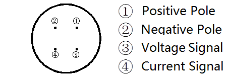
- Pin details: Pin 1 – Power (brown wire), Pin 2 – Ground (black wire), Pin 3 – Signal (blue wire)
Internal Circuitry of the Sensor
You can open the sensor by removing the knots. The internal circuitry has Photovoltaic modules, an industrial processor, the current generator which are integrated into the internal drive.

The material of the circuit PCB is military-grade A. This ensures the stability of the parameters and the quality of the electrical properties. The internal Electronic components are all industrial chip which has extremely reliable electromagnetic interference resistance. The internal system can work normally in – 20 ℃ ~ + 50 ℃, humidity 35% ~ 85%.
The plug of the cable is a military plug. It has a good anticorrosive and prevents erosion performance that it can ensure the instrument used for a long time.
Measure Wind Speed using Anemometer & Arduino
Now let us interface the Adafruit Anemometer Sensor with Arduino & measure the wind speed. Check the schematic or circuit below.

The Adafruit Anemometer works between 7-24V DC. So the voltage from the Arduino is not enough to power on the sensor. Hence I have to use MT3608 DC-to-DC Boost Converter Module to boost the 3.7V from Lithium-Ion Battery to 7.5V. To adjust the output voltage, connect the battery first to the input of the MT3608 Module and then rotate the potentiometer until the output voltage shows 7.5V on multimeter.
The Sensor VCC wire and the Arduino Vin pin are supplied with 7.5V from the output of the Boost Converter Module. The blue wire that is the analog output pin of the anemometer sensor is connected to the A0 of Arduino. Similarly the I2C Pin of OLED Display, i.e SDA & SCL is connected to A4 & A5 of Arduino. The OLED Display is supplied with 3.3V from Arduino 3.3V Pin.

Project PCB Gerber File & PCB Ordering Online
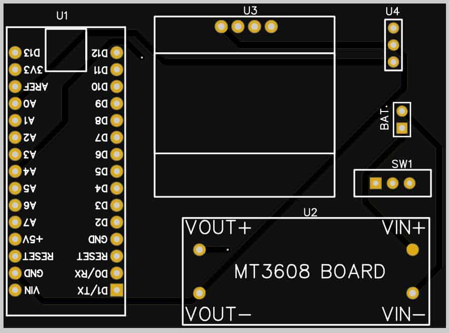
If you don’t want to assemble the circuit on a breadboard and you want PCB for the project, then here is the PCB for you. I used EasyEDA to design the PCB. The PCB Board for Arduino Anemometer looks something like below.

<
The Gerber File for the PCB is given below. You can simply download the Gerber File and order the PCB from ALLPCB at 1$ only.
You can use this Gerber file to order high quality PCB for this project. To do that visit the ALLPCB official website by clicking here: https://www.allpcb.com/.

You can now upload the Gerber File by choosing the Quote Now option. From these options, you can choose the Material Type, Dimensions, Quantity, Thickness, Solder Mask Color and other required parameters.

After filling all details, select your country and shipping method. Finally you can place the order.
You can assemble the components on the PCB Board.
Source Code/Program for Arduino Anemometer
Here is a simple Arduino Anemometer code written for Arduino IDE. The Arduino anemometer project code can be compiled and uploaded to the Arduino Board. You can either change the wind speed to m/s or mph.
The code requires SSD1306 & GFX OLED library for compilation. First download the following libraries and add it to the Arduino IDE.
- Download SSD1306 Library: https://github.com/adafruit/Adafruit_SSD1306
- Download Adafruit GFX Library: https://github.com/adafruit/Adafruit-GFX-Library
You can now copy the code and upload it to the Arduino Board.
|
1 2 3 4 5 6 7 8 9 10 11 12 13 14 15 16 17 18 19 20 21 22 23 24 25 26 27 28 29 30 31 32 33 34 35 36 37 38 39 40 41 42 43 44 45 46 47 48 49 50 51 52 53 54 55 56 57 58 59 60 61 62 63 64 65 66 67 68 69 70 71 72 73 74 75 76 77 |
#include <Adafruit_GFX.h> #include <Adafruit_SSD1306.h> #define SCREEN_WIDTH 128 // OLED display width, in pixels #define SCREEN_HEIGHT 64 // OLED display height, in pixels #define OLED_RESET 4 // Reset pin # (or -1 if sharing reset pin) Adafruit_SSD1306 display(SCREEN_WIDTH, SCREEN_HEIGHT, &Wire, OLED_RESET); void setup() { Serial.begin(9600); if (!display.begin(SSD1306_SWITCHCAPVCC, 0x3C)) { Serial.println(F("SSD1306 allocation failed")); for (;;); // Don't proceed, loop forever } display.display(); delay(100); display.clearDisplay(); display.clearDisplay(); display.setTextColor(WHITE); display.setTextSize(2); display.setCursor(0, 20); display.print("Anemometer"); display.display(); delay(3000); } void loop() { float sensorValue = analogRead(A0); Serial.print("Analog Value ="); Serial.println(sensorValue); float voltage = (sensorValue / 1023) * 5; Serial.print("Voltage ="); Serial.print(voltage); Serial.println(" V"); float wind_speed = mapfloat(voltage, 0.4, 2, 0, 32.4); float speed_mph = ((wind_speed *3600)/1609.344); Serial.print("Wind Speed ="); Serial.print(wind_speed); Serial.println("m/s"); Serial.print(speed_mph); Serial.println("mph"); display.clearDisplay(); display.setTextSize(1); display.setCursor(30, 0); display.println("Wind Speed"); // display.setTextSize(2); // display.setCursor(25, 30); // display.print(wind_speed, 1); // display.setTextSize(1); // display.print(" m/s"); display.setTextSize(2); display.setCursor(25, 30); display.print(speed_mph, 1); display.setTextSize(1); display.print(" mph"); display.display(); Serial.println(" "); delay(300); } float mapfloat(float x, float in_min, float in_max, float out_min, float out_max) { return (x - in_min) * (out_max - out_min) / (in_max - in_min) + out_min; } |
Code Explanation
Here is a complete explanation of arduino anemometer code line by line.
|
1 2 |
#include <Adafruit_GFX.h> #include <Adafruit_SSD1306.h> |
First we include the library for OLED Display as it requires two libraries called Adafruit SSD1306 Library for SSD1306 OLED Driver and Adafruit GFX Library for Graphics Display.
|
1 2 3 4 |
#define SCREEN_WIDTH 128 // OLED display width, in pixels #define SCREEN_HEIGHT 64 // OLED display height, in pixels #define OLED_RESET 4 // Reset pin # (or -1 if sharing reset pin) Adafruit_SSD1306 display(SCREEN_WIDTH, SCREEN_HEIGHT, &Wire, OLED_RESET); |
Then we define OLED Display height, width, reset pin & create instances for OLED Display.
|
1 2 3 4 5 6 |
Serial.begin(9600); if (!display.begin(SSD1306_SWITCHCAPVCC, 0x3C)) { Serial.println(F("SSD1306 allocation failed")); for (;;); // Don't proceed, loop forever } |
Under the setup section we initialized the Serial and OLED function. The I2C Address of the OLED Display is 0x3c. Some OLED Display has an address of 0x3D. Change the I2C Address in case OLED is not working.
|
1 2 |
float sensorValue = analogRead(A0); float voltage = (sensorValue / 1023) * 5; |
Then we are reading the sensor analog value and then converting the value into voltage.
|
1 |
float wind_speed = mapfloat(voltage, 0.4, 2, 0, 32.4); |
Mapping the voltage to speedy is straightforward. The wind speed starts at 1m/s at 0.4V with a maximum of 32.4m/s at around 2. Arduino has a built-in map() function, but the map() does not work for floats, so we have a simple mapFloat() function.
|
1 2 3 4 |
float mapfloat(float x, float in_min, float in_max, float out_min, float out_max) { return (x - in_min) * (out_max - out_min) / (in_max - in_min) + out_min; } |
This functions is used to map the variable under a float.
|
1 |
float speed_mph = ((wind_speed *3600)/1609.344); |
Using this line you can convert the wind speed from m/s to miles per hour (mph).
|
1 2 3 4 5 6 7 8 9 10 11 |
// display.setTextSize(2); // display.setCursor(25, 30); // display.print(wind_speed, 1); // display.setTextSize(1); // display.print(" m/s"); display.setTextSize(2); display.setCursor(25, 30); display.print(speed_mph, 1); display.setTextSize(1); display.print(" mph"); |
These line displays the wind speed in OLED Display. You can comment or uncomment the above lines on the basis of m/s or mph requirement.
Measuring Wind Speed & Testing the Device

Once you upload the Arduino Anemometer code to the Arduino Board, the OLED Display will start displaying the wind speed. When the anemometer cup is stable the OLED will show speed around 0.1m/s to 0.3m/s. The speed will vary or increase when the sensor is taken in a windy region. I used my home roof to check the wind speed.
Initialy I tried measuring the speed in m/s and got the result as shown in the image below. The speed variation is increases or decreases depending upon the blade rotation.

Then I used the industrial standard measurement and converted the m/s to miles per hour (mph). You can also use the mathematical calculation to convert the speed to a kilometer per hour (kph).

This is how you can make DIY Arduino Anemometer Project for measuring wind speed for Weather Station.
Video Tutorial & Guide

You can also check the better version of this project using ESP32, where you can display the Wind Speed on TFT LCD Display with widgets.

Check it here: Wind Speed Display on TFT LCD
In case if you need a digital version of Anemometer, then you can check the NPN Pulse Output Anemometer which operates only at 5V.

")


12 Comments
Could use this code with Arduino Mkr zero ?
From what I have learned that I should connect Vin pin with Anemometer Vcc (brown wire) & 7-24v DC converter, Right?
I have used another codes but the values from Arduino Mkr zero was different than what was in Arduino.
The Arduino UNO/Nano/mini Board has 10-bit ADC whereas the Arduino Mkr Board has 12-Bit ADC. This is why you are getting two different values from two different board. To use the same code with Arduino Mkr Board, replace 1023 with 4096 in the code part. You will then get the same value.
Thank you for your ply.
Is this a normal reading?
I use a AC/DC adapter set on 9V.
Analog Value =1.00
Voltage =0.00 V
Wind Speed =-8.08m/s
-18.06mph
Analog Value =1.00
Voltage =0.00 V
Wind Speed =-8.08m/s
-18.06mph
Analog Value =1.00
Voltage =0.00 V
Wind Speed =-8.08m/s
-18.06mph
Analog Value =0.00
Voltage =0.00 V
Wind Speed =-8.10m/s
-18.12mph
Have you used Sigfox technology before?
I’m facing a problem of convert data to Hexadecimal.
Sorry Sir, no idea about this anemometer. Different anemometer has different ways of measuring the wind speed. Some measures pulse count and some measures analog voltage whereas some measures frequency. You have to go through the manufacturer specifications and write your own code.
Hello! Im new to arduino, and i tried this with arduino uno but then i get error while uploading the code. please help
Is this line correct ” float voltage = (sensorValue / 1023) * 5;”?
How about this line:
float voltage =sensorValue* (5/ 1023) ;
Hi…..wow the Wonderful World of Electronics has blossomed… been a long time for me..great Web Site.
Can this great little Anemometer project be made to supply a NMEA 0183 VWR Sentence via some sort of conversion?
It would be a super awesome project (for me) to get back into modern day electronics.
Cheers & thanks
Doog
Why it says like this ” No such file or directory #include ^~~~~~~~~~~~~~~~~~~~~~” after verify the coding?
Are there any plans to add a logging function that stores measured wind parameters with a time stamp locally in memory so that they can be downloaded later via a serial interface to a laptop . This is necessary to gather wind data over extended periods of time to evaluate the wind resources at a potential site for a wind turbine for example .
You can use a SD Card module to the arduino and add few lines of code to store data log in sd card.
I wouldn’t trust the pcb design. I purchased pcb’s from another project of thiers and the pcb doesn’t work. I found an error in the design but they have yet to correct the error even after I informed them of it.
Can we add solar power instead of lithium battery?