

Overview
In this post, we will learn how we can design a 3.7V to 9V Boost Converter Circuit using MC34063 DC−to−DC converter IC. Most of the time we only have a battery as a power source. The lithium-Ion or Lithium Polymer Battery can produce a voltage of 3.7V. The 3.7V may not be enough to drive certain circuits where the power requirement is high. Hence, we need to convert the low power DC, to high power DC without the need for any additional large component.
In this case DC−to−DC converter comes into the frame. DC-DC converters are widely used to efficiently produce a regulated voltage from a source that may or may not be well controlled to a load that may or may not be constant. A Buck Converter outputs a lower voltage than the original voltage, while a Boost Converter supplies a higher voltage.
In this circuit we will convert the voltage from Lithium-Ion Battery to 9V. The device uses an inductor and a few resistors or capacitors along with MC340C3 IC. The 3V to 9V Boost Converter Circuit can be used to power the device that requires higher voltages for operations. You can check one of our previous post for designing 3.7 to 5V Boost Converter using the same MC34063 IC.
Bill of Materials
The list of components that we need for designing 3.7V to 9V Boost Converter Circuit is given below. You can purchase all the components from Amazon.
| S.N. | Components Name | Description | Quantity |
|---|---|---|---|
| 1 | MC34063 | DC-DC Converter IC | 1 |
| 2 | 1N5819 | Schottky Diode | 1 |
| 3 | 100uH | Inductor | 1 |
| 4 | 100uF | Capacitor | 3 |
| 5 | 1nF | Capacitor | 1 |
| 6 | 6.2K | Resistor | 1 |
| 7 | 1K | Resistor | 1 |
| 8 | 180 0hm | Resistor | 1 |
| 9 | 0.22 ohm | Resistor | 1 |
| 10 | 3.7V Battery | 3.7V Lithium-Ion/Lithium Polymer Battery | 1 |
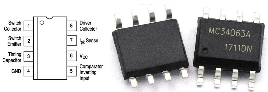
MC34063 IC
The MC34063A Buck-Boost Converter IC is a monolithic control circuit containing the primary functions required for DC−to−DC converters. The IC consist of an internal temperature compensated reference, comparator, controlled duty cycle oscillator with an active current limit circuit, driver, and high current output switch. The IC was specifically designed to be incorporated in Step−Down and Step−Up and Voltage−Inverting applications with a minimum number of external components.
Features of MC34063 IC
1. Operation from 3.0 V to 40 V Input
2. Low Standby Current
3. Current Limiting
4. Output Switch Current to 1.5 A
5. Output Voltage Adjustable
6. Frequency Operation to 100 kHz
7. Precision 2%
3.7V to 9V Boost Converter Circuit/Schematic
The heart of the circuit is the switching regulator IC MC34063A. The 1N5819 is a Schottky diode with a low forward voltage drop and high switching speed. It is commonly used in high frequency applications like Inverters or any DC-DC converters etc.

As MC34063A works up to 40V, thus the circuit works with DC voltage in the range of 3.0V to 40.0V. We are using 3.7V as input from Lithium-Ion Battery. MC34063A can provide a high output switch current up to 1.5A we need to provide a specific inductor. It can provide adjustable output voltage and has short circuit current limiting and low standby current. The current can be adjusted with the help resistor R1 in the circuit. For the fixed 9V output, we connect a 100uF capacitor. It will filter an excess noise from the power supply out.
Circuit Assembly & Testing
Initially, you can use the breadboard to assemble the circuit. It is a good idea to first test the circuit on a breadboard before going for the PCB part.

You can connect all the components with each other on a breadboard. After the circuit assembly, you can power the circuit using a 3.7V Lithium-Ion Battery as input. The output is taken from the 100uF capacitor. The circuit immediately shows 9V output on a multimeter after supplying input voltage.
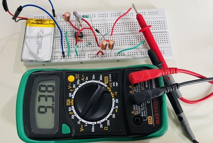
The MC34063 9V Boost Converter circuit works very fine. But a little higher voltage is observed on a multimeter. This is because of the breadboard metallic surface which adds extra resistance to the circuit. This can be eliminated if you assemble the circuit on a Vero board or a PCB Board.

Once you assemble the circuit on the PCB Board, you can again connect a 3V or 3.7V Battery to the input. As soon as you connect the battery, the output of 9V is shown in the multimeter. This time the circuit is stable and the output is exactly around 9V. This is how you can use MC34063 as 3v to 9v boost converter.

Project PCB Gerber File & PCB Ordering Online
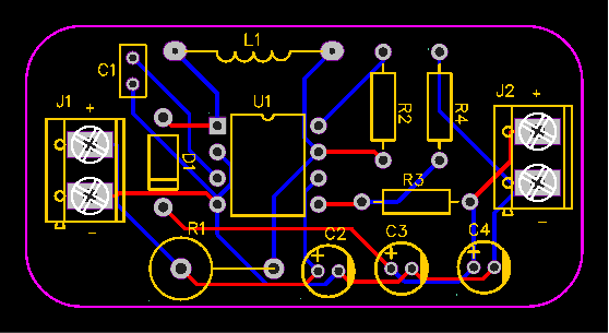
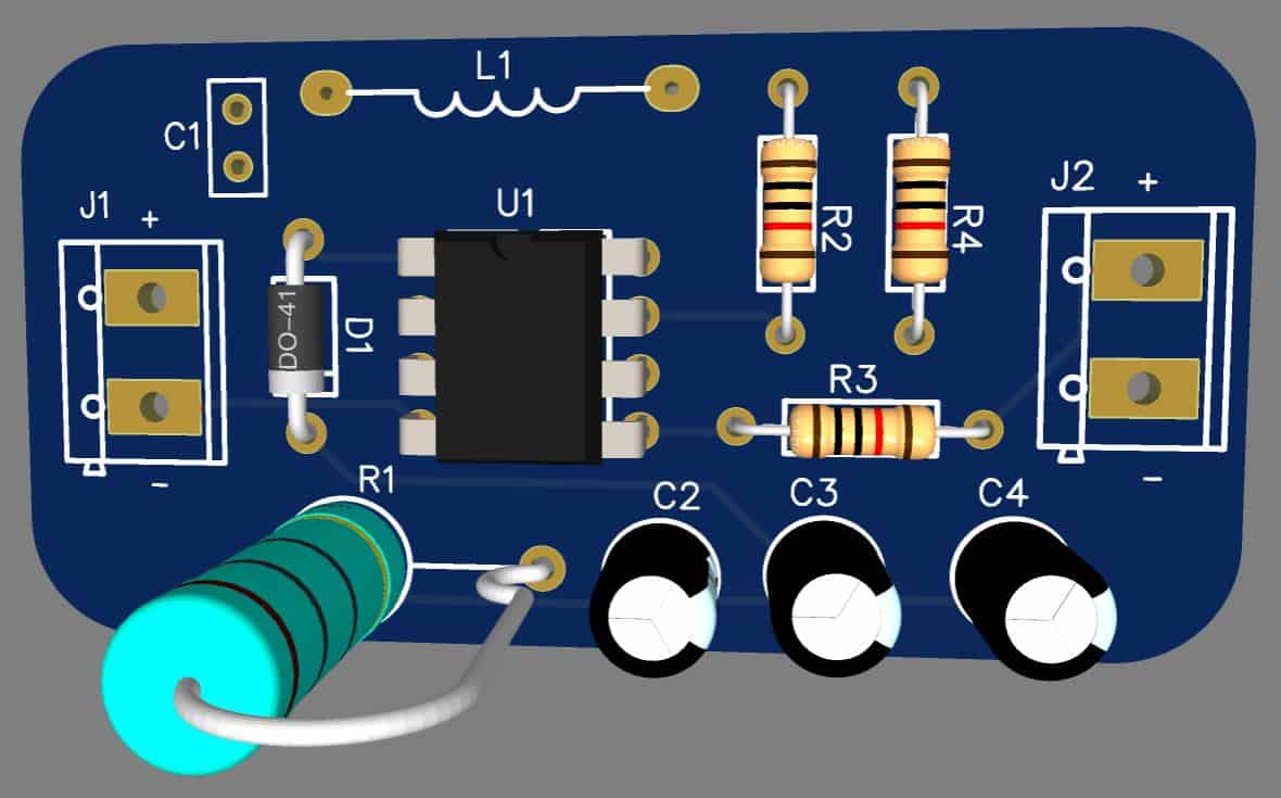
If you don’t want to assemble the circuit on a breadboard and you want PCB for the project, then here is the PCB for you. The PCB Board for the 3.7V to 9V Boost Converter is designed using EasyEDA online Circuit Schematics & PCB designing tool. The PCB looks something like below.
The Gerber File for the PCB is given below. You can simply download the Gerber File and order the PCB from ALLPCB at 1$ only.
You can use this Gerber file to order high quality PCB for this project. To do that visit the ALLPCB official website by clicking here: https://www.allpcb.com/.

You can now upload the Gerber File by choosing the Quote Now option. From these options, you can choose the Material Type, Dimensions, Quantity, Thickness, Solder Mask Color and other required parameters.

After filling all details, select your country and shipping method. Finally you can place the order.
You can assemble the components on the PCB Board.
Video Tutorial & Demonstration


3 Comments
Hello,
I Think there is an error in your schematic.
I tried your circuit and it won’t work.
Then checked that IC typical circuit and it seems L1 conects ro R1 and to IC pin6. That junction connects to R2 and R2 connects to pin IC pin 7.
Cheers.
Hello! Thank you for the comment and noticing the mistake. I have corrected the schematic now.
Hi, I have a dc input source between 5v and 30v. Can I convert 9v or 12v with this circuit?