

Overview:
In this tutorial, we will interface an Ultrasonic Anemometer with Arduino to measure wind speed and direction.
An ultrasonic anemometer utilizes ultrasonic waves to measure both the speed and direction of wind. Unlike traditional mechanical anemometers, which rely on spinning cups or vanes to measure wind, ultrasonic anemometers have no moving parts. This feature makes them durable, reliable, and well-suited for a variety of challenging environments.
The term ‘anemometer‘ is derived from the Greek word ‘anemos,’ which means ‘wind.’ Ultrasonic anemometers are widely used in applications like meteorology, wind energy studies, navigation, and research. These instruments are particularly useful in settings that require high levels of accuracy and real-time data collection.
In this project, we will use a Renkeer Ultrasonic Anemometer that is especially designed for outdoor measurements. The sensor can measure wind speed ranging from 0 to 40 m/s and wind direction from 0 to 360° with high accuracy. The anemometer operates on a low-power chip, consuming only 0.12W, making it suitable for solar or battery-powered installations.

For interfacing, we will employ the RS485 protocol. Similar to our previous tutorial on the Pyranometer Sensor, the RS485 Module will facilitate the transfer of data from the sensor to the Arduino board. The wind speed and direction data will then be displayed on a 16×2 LCD screen connected to the Arduino.
Bill of Materials
Following are the components that we need for Ultrasonic Anemometer data using an Arduino. The components can be purchased from given links.
| S.N. | Components | Quantity | Purchase Link |
|---|---|---|---|
| 1 | Arduino UNO Board | 1 | Amazon | AliExpress | SunFounder |
| 2 | Ultrasonic Anemometer | 1 | Renkeer |
| 3 | 16X2 I2C LCD Display | 1 | Amazon | AliExpress | SunFounder |
| 4 | MAX485 Module | 1 | Amazon | AliExpress | SunFounder |
| 5 | 12V Power Supply | 1 | Amazon | AliExpress | SunFounder |
| 6 | Jumper Wires | 10 | Amazon | AliExpress | SunFounder |
| 7 | Breadboard | 1 | Amazon | AliExpress | SunFounder |
Ultrasonic Anemometer Sensor
An ultrasonic anemometer is a specialized instrument that measures wind speed and direction, quantifying them in meters per second (m/s) and degrees (°), respectively. The wind conditions can vary significantly over short distances due to factors such as time of day, geographical location, and obstacles like buildings or terrain.

Ultrasonic anemometers measure wind speed by detecting the difference in time taken for an ultrasonic pulse to travel in each direction between pairs of transducers caused by movement of the air. This method allows accurate measurement even at low wind speeds as there is no mechanical inertia to overcome.

Renkeer Ultrasonic Anemometer
The Renkeer Ultrasonic Anemometer is an innovative device engineered for the precise outdoor measurement of wind speed and direction. It stands out for its compact design, absence of movable parts, and high protection level, making it exceptionally durable and suitable for harsh environments.

Internally, the anemometer uses low-power chips, keeping its power consumption to an efficient 0.12W. This makes it an ideal choice for solar or battery-powered installations, particularly in settings that require reliable, long-term data collection. The device’s technology ensures a compact structure, further complemented by optional modules for measuring temperature and air pressure. The anemometer offers a range of output signals including 420mA, 05V, 0~10V, and RS485, providing users with flexible interfacing options.

The shell of the anemometer is made from high-strength ABS material, which adds to its adaptability for use across different environmental conditions. With its combination of precision, durability, and affordability, the Renkeer Ultrasonic Anemometer is a valuable tool for anyone looking to accurately measure wind conditions.
Specifications of Renkeer Ultrasonic Anemometer
- Power supply: 10-30V DC
- Wind Speed Range: 0~40m/s
- Wind Direction Range: 0~360°
- Wind Speed Measurement Accuracy: ±0.5+2%FS(60%RH,25℃)
- Wind Direction Measurement Accuracy: ±3°(60%RH,25℃)
- Wind Speed Resolution: 0.01 m/s
- Wind Direction Resolution: 1°
- Working environment: -40~80℃, 0~95%RH
- Wind resistance: 75 m/s
- Response time: 1S
- Protection level: IP65
- Output signal: 4~20mA, 0~5V, 0~10V, RS485
- Starting wind speed: 0.5m/s
Sensor Circuitary & Pinout
Here is the internal circuitary of the Ultrasonic Anemometer Sensor.
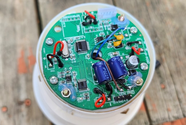
The Ultrasonic Anemometer works on RS485 Protocol and hence can communicate with easily with Arduino, ESP32 or any other microcontrollers using MAX485 Module.
Here are the 4 wires for the sensor.

- Brown Wire: VCC (10-30V)
- Black Wire: GND
- Yellow Wire: RS485-A
- Blue Wire: RS485-B
Data Frame Format Definition & Communication Protocol
Data frame format definition
Using the Modbus-RTU communication protocol, the format is as follows:
- Initial structure ≥ 4 bytes of time
- Address code = 1 byte
- Function code = 1 byte
- Data area = N bytes
- Error check = 16-bit CRC code
- Time to end structure ≥ 4 bytes
Host query frame structure:
| Address Code | Function Code | Register Start Address | Register Length | Check code Low Bit | Check Code High Bit |
| 1 byte | 1 byte | 2 bytes | 2 bytes | 1 byte | 1 byte |
Slave response frame structure:
| Address Code | Function Code | Effective Bytes | Data Area 1 | Data Area 2 | Data Area N | Check Code Low Byte | Check Code High Byte |
| 1 byte | 1 byte | 1 byte | 2 bytes | 2 bytes | 2 bytes | 1 bytes | 1 bytes |
Read the Wind Speed and Direction Value
Inquiry frame:
| Address Code | Function Code | Initial Address | Data Length | Check code Low Bit | Check Code High Bit |
| 0x01 | 0x03 | 0x00 0x00 | 0x00 0x02 | 0xC4 | 0x0B |
Response frame:
| Address Code | Function Code | Returns the number of valid bytes | Real-time wind speed value | Real-time wind direction value | Check code low bit | Check code high bit |
| 0x01 | 0x03 | 0x04 | 0x00 0x7D | 0x00 0x5A | 0xEA | 0x10 |
The Wind Speed and Direction from the response frame can be calculated as:
007D (hexadecimal) =125=> Wind Speed=1.25 m/s
005A (hexadecimal) =90=> Wind Direction=90°N
Interfacing Ultrasonic Anemometer with Arduino
Now lets interface the Ultrasonic Anemometer with Arduino & start measuring the Wind Speed and Direction.
Hardware Connection
Here is the schematic for the project.

The Ultrasonic Anemometer communicates with a Microcontroller using RS485 protocol. Hence we used MAX485 Module for this project. The MAX485 is a popular RS-485 transceiver chip commonly used for serial communication. When interfacing the MAX485 with an Arduino, you’ll typically be dealing with half-duplex communication, where data transmission and reception occur at different times.

Here is a connection mapping between MAX485 & Arduino.
- VCC (MAX485) -> 5V (Arduino)
- GND (MAX485) -> GND (Arduino)
- RO (MAX485) -> 2 (Digital Pin of Arduino)
- DI (MAX485) -> 3 (Digital Pin of Arduino)
- RE (MAX485) -> 8 (Digital Pin of Arduino)
- DE (MAX485) -> 7 (Digital Pin of Arduino)
Here is a connection mapping between MAX485 & Pyanometer Sensor.
- VCC -> 12V (Anemometer)
- GND -> GND (Anemometer)
- A (MAX485) -> Anemometer A Pin (Yellow Color)
- B (MAX485) -> Anemometer B Pin (Blue Color)

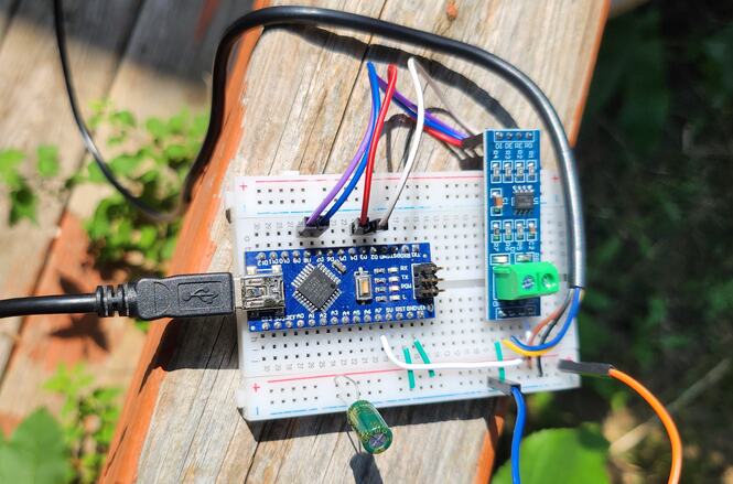
You may use a breadboard for assembly and a jumper wires for connecting the sensor and RS485 Module with Arduino. The Ultrasonic Anemometer requires 12V for operation. You may use a 12V Battery or a 12V DC Power Supply.
Source Code/Program for Reading Wind Speed/Direction Value
After assembling the sensor as per the circuit diagram above, lets move to the coding part of this project. According to the above table the inquiry frame for getting the Sensor reading hexadecimal is as follows:
|
1 |
0x01, 0x03, 0x00, 0x00, 0x00, 0x02, 0xC4, 0x0B |
The sensor communicates at a baudrate of 4800. We have set the same parameter in the code to get the required reading.
Copy the following code and paste it on your Arduino IDE.
|
1 2 3 4 5 6 7 8 9 10 11 12 13 14 15 16 17 18 19 20 21 22 23 24 25 26 27 28 29 30 31 32 33 34 35 36 37 38 39 40 41 42 43 44 45 46 47 48 49 50 51 52 53 54 55 56 57 58 59 60 61 62 63 64 65 66 67 68 69 70 71 72 73 |
#include <SoftwareSerial.h> #define RE 8 #define DE 7 const byte anemometer[] = {0x01, 0x03, 0x00, 0x00, 0x00, 0x02, 0xC4, 0x0B}; byte values[9]; SoftwareSerial mod(2, 3); void setup() { Serial.begin(9600); mod.begin(4800); pinMode(RE, OUTPUT); pinMode(DE, OUTPUT); delay(1000); } void loop() { // Transmit the request to the sensor digitalWrite(DE, HIGH); digitalWrite(RE, HIGH); delay(10); mod.write(anemometer, sizeof(anemometer)); digitalWrite(DE, LOW); digitalWrite(RE, LOW); delay(10); // Wait until we have the expected number of bytes or timeout unsigned long startTime = millis(); while (mod.available() < 9 && millis() - startTime < 1000) { delay(1); } if (mod.available() >= 9) { // Read the response byte index = 0; while (mod.available() && index < 9) { values[index] = mod.read(); Serial.print(values[index], HEX); Serial.print(" "); index++; } Serial.println(); // Parse the Wind Speed value int Wind_Speed_Int = int(values[3] << 8 | values[4]); float Wind_Speed_m_s = Wind_Speed_Int / 100.0; float Wind_Speed_kph = Wind_Speed_m_s * 3.6; // Conversion to km/h Serial.print("Wind Speed: "); Serial.print(Wind_Speed_kph); Serial.println(" km/h"); // Parse the Wind Direction value int Wind_Direction = int(values[5] << 8 | values[6]); Serial.print("Wind Direction: "); Serial.print(Wind_Direction); Serial.println(" degrees"); } else { Serial.println("Sensor timeout or incomplete frame"); } delay(1000); } |
Testing & Results
To upload the code to the Arduino Nano Board, select Arduino Nano from Board list. Then Select the COM Port. Finally click on the upload button to upload the code.
Once code is uploaded, open the Serial Monitor and you will see following readings.
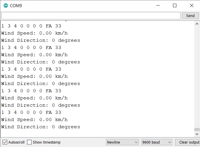
The wind speed and direction, both will appear zero when no wind is blowing.
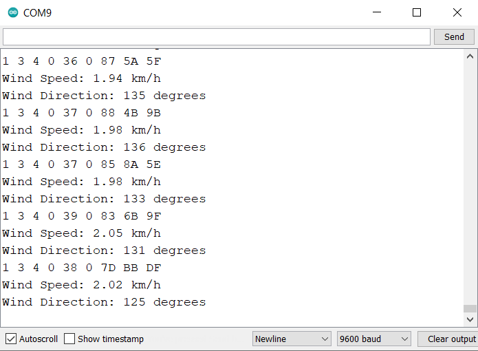
When the wind blows, the wind speed values in Km/H and Wind Direction in degrees is displayed.
The wind speed and direction measured by an ultrasonic anemometer are influenced by a variety of factors. These include time of day, as wind patterns can shift from morning to evening, and geographical elements like the presence of hills, valleys, or man-made structures that can channel or obstruct wind flow.
Interfacing Ultrasonic Anemometer with Arduino & LCD Display
Now lets interface the Ultrasonic Anemometer with Arduino and 16×2 I2C LCD Display and observe the Wind Speed and Direction Value on LCD.
Hardware Connection
Here is the connection diagram for adding an extra LCD connection.

The sensor and RS485 connections remains same as above. Only the connection for LCD changes as follows:
- VCC (LCD) -> 5V (Arduino)
- GND (LCD) -> GND (Arduino)
- SDA (LCD) -> A4 (Arduino)
- SCL (LCD) -> A5 (Arduino)

Source Code/Program Displaying Wind Speed/Direction Value on LCD
The code requires I2C LCD Library for compilation. Therefore download the library and add it to the Arduino library folder.
Now copy the following code and paste it to the Arduino IDE.
|
1 2 3 4 5 6 7 8 9 10 11 12 13 14 15 16 17 18 19 20 21 22 23 24 25 26 27 28 29 30 31 32 33 34 35 36 37 38 39 40 41 42 43 44 45 46 47 48 49 50 51 52 53 54 55 56 57 58 59 60 61 62 63 64 65 66 67 68 69 70 71 72 73 74 75 76 77 78 79 80 81 82 83 84 85 86 87 88 89 90 91 92 |
#include <SoftwareSerial.h> #include <LiquidCrystal_I2C.h> LiquidCrystal_I2C lcd(0x27, 16, 2); // set the LCD address to 0x27 for a 16 chars and 2 line display #define RE 8 #define DE 7 const byte anemometer[] = {0x01, 0x03, 0x00, 0x00, 0x00, 0x02, 0xC4, 0x0B}; byte values[9]; SoftwareSerial mod(2, 3); void setup() { Serial.begin(9600); lcd.init(); lcd.backlight(); mod.begin(4800); pinMode(RE, OUTPUT); pinMode(DE, OUTPUT); lcd.setCursor(2, 0); lcd.print("Wind Speed"); lcd.setCursor(2, 1); lcd.print("Measurement"); delay(3000); } void loop() { // Transmit the request to the sensor digitalWrite(DE, HIGH); digitalWrite(RE, HIGH); delay(10); mod.write(anemometer, sizeof(anemometer)); digitalWrite(DE, LOW); digitalWrite(RE, LOW); delay(10); // Wait until we have the expected number of bytes or timeout unsigned long startTime = millis(); while (mod.available() < 9 && millis() - startTime < 1000) { delay(1); } if (mod.available() >= 9) { // Read the response byte index = 0; while (mod.available() && index < 9) { values[index] = mod.read(); Serial.print(values[index], HEX); Serial.print(" "); index++; } Serial.println(); // Parse the Wind Speed value int Wind_Speed_Int = int(values[3] << 8 | values[4]); float Wind_Speed_m_s = Wind_Speed_Int / 100.0; float Wind_Speed_kph = Wind_Speed_m_s * 3.6; // Conversion to km/h Serial.print("Wind Speed: "); Serial.print(Wind_Speed_kph); Serial.println(" km/h"); // Parse the Wind Direction value int Wind_Direction = int(values[5] << 8 | values[6]); Serial.print("Wind Direction: "); Serial.print(Wind_Direction); Serial.println(" degrees"); lcd.clear(); lcd.setCursor(0, 0); lcd.print("Speed:"); lcd.print(Wind_Speed_kph); lcd.print(" kph"); lcd.setCursor(0, 1); lcd.print("Dir:"); lcd.print(Wind_Direction); lcd.print(" deg."); delay(1000); } else { Serial.println("Sensor timeout or incomplete frame"); } } |
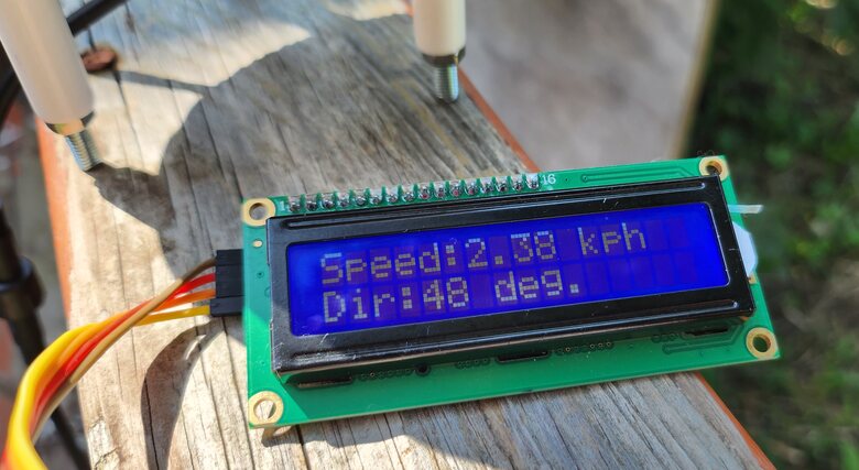
Testing & Results
Upload the code to the Arduino Nano Board. The Arduino code is now ready to give the Wind Speed and Direction reading on LCD Display.
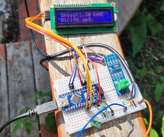
The Wind Speed and direction varies depending upon the Wind blowing speed.
Additionally, the geographical region itself can contribute to the overall wind conditions, with certain areas more prone to consistent winds and others to variable gusts.
Video Tutorial & Guide

Conclusion
In conclusion, this tutorial provided a comprehensive guide on interfacing a Renkeer Ultrasonic Anemometer with an Arduino to measure wind speed and direction. Utilizing the RS485 protocol, we successfully transferred the sensor’s data to the Arduino and displayed it on a 16×2 LCD screen.
The advantages of using an ultrasonic anemometer over traditional mechanical options were evident in its durability, reliability, and adaptability to various environmental conditions. Its low power consumption of 0.12W also made it ideal for solar or battery-powered setups. With its high-accuracy measurements ranging from 0 to 40 m/s for wind speed and 0 to 360° for wind direction, the Renkeer Ultrasonic Anemometer proved to be an excellent choice for anyone looking to study or monitor wind conditions accurately.

")


1 Comment
Hi there! I got a question regarding the ultrasonic anemometer. I also got one myself from the renkee but mine have 6 wires instead of 4 i suppose that they are Data + and – for the wind speed and data + and – for direction. Do you have any idea how to inteface this type of anemometer with the Arduino?
Thanks and Regards
Peter