

Overview
In this post, we will give a detailed guide for Raspberry Pi Pico Primer Kit for Beginners & Students. The Raspberry Pi Pico is a low-cost, high-performance microcontroller board with multiple interfaces. It features the RP2040 microcontroller. As RPI Pico is born with powerful performance, reasonable prices, and comprehensive resources, it will definitely become a great platform for learning and mastering electronic knowledge.
To help the learners to start with Pico, Makerfabs has prepared the Pico starter Kit as the first development tool kit. The kit is compatible with the Raspberry PI official guidebook. The primer kit is composed of many kinds of sensors & actuators modules, with the standard connectors. So it is like plug & play module as you just need to connect the module and start programming.
In this guide, we will go through the details of all the sensors and modules interfacing with Raspberry Pi Pico using MicroPython Code. But before starting please check the Raspberry Pi Pico Getting Started tutorial. The previous post explains the method to install MicroPython of your PC & upload bootloader on Raspberry Pi Pico Board.
Raspberry Pi Pico Primer Kit for Beginners & Students
The Raspberry Pi Pico Primer Kit is the development shield of Pi Pico. The kit includes the main board and some modules like Servo, Slide potentiometer, DHT11 sensor, Relay, MPU6050, ESP8266 & HC-SR04. The mainboard base on the Pico and LCD display, features three buttons, three LEDs, and a buzzer. It also provides six interfaces to connect the peripheral modules.
Parts List:

- Raspberry Pi Pico
- PICO Primer Expansion Board
- 6Aixs IMU MPU6050
- DHT11 Humidity TemperatureSensor
- Relay Module
- WS2812 LED Strip
- Servo Motor SG90
- Slide Potentiometer
- Serial WiFi ESP-12
- Ultrasonic Sensor HC-SR04
Diagram & Interfaces

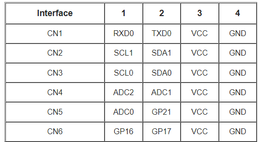
The board has multiple interfaces with 6 connectors. The connectors are named as CN1, CN2,…..CN6 that are having UART, I2C, ADC & Digital Interfaces.
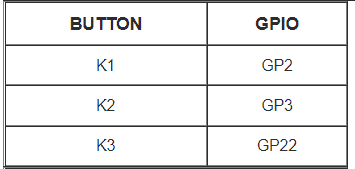
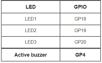
It also has 3 push buttons, 3 LEDs, and a Buzzer.
Thonny IDE & MicroPython Setup for Pi Pico
- Now let us get started with Raspberry Pi Pico using MicroPython on Thonny IDE. First you have to download Thonny from the https://thonny.org/

- Connect the Raspberry Pi Pico to your computer. Then from Thonny go to Tools > Options and click on the Interpreter tab. From the interpreter dropdown list, select MicroPython (Raspberry Pi Pico). The port dropdown menu can be left to automatically detect the Pico. Click Ok to close.

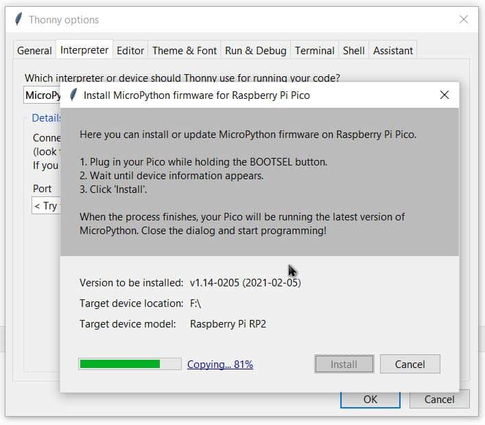
- When you plugin the pico Board, a firmware installation tab will appear for raspberry pi pico. Click on Install & some files will be downloaded.
- After successful installation, the MicroPython version and Raspberry board will appear in the Python Shell. To test we can write a quick print function to say “Hello World”. Press Enter to run the code. You will get Hello World as a response.

Adding Libraries to Raspberry Pi Pico
Connect Pico to PC. Click “stop” to connect the Pico.

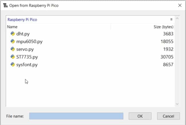
Obtain all the Libraries code from Github Link.

Upload all these Libraries to Pico Board.
Project 0: Display Test
This is a Display test code. This checks whether the code works well with Raspberry Pi Pico Beginners Kit or not. The display used here is 1.44 inch TFT LCD, with ST7735 driver.
Run the test_display.py on Thonny IDE.

Project 1: LED Control & Display
The board has 3 push buttons as K1, K2 & K3. It also has 3 LEDs with yellow, green, blue color & a buzzer.
Run the test_button_led.py and project-1-display_led_button.pyon Thonny IDE.

- Press the K1 button to control the LED1 turning on/off.
- Press the K2 button to control the LED2 turning on/off.
- Press the K3 button to control the LED3 turning on/off.
Project 2: MPU6050 Demo
Connect a MPU6050 Sensor to the Pico Board CN3 port. The MPU6050 along with RPI Pico will display some simple graphic level & read inclination angle.
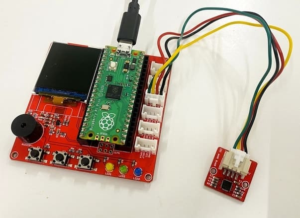
Run the test_imu.py and project-2-leveling.py on Thonny IDE.

Rotate the MPU6050 module at will, and the circle displayed on the screen will change position.
Project 3: Reading ADC Value with Potentiometer
Connect Slide potentiometer module to the CN5 port. The potentiometer is connected to the Analog Pin of Raspberry Pi Pico and can be used to read the 12-bit Analog value & convert into input Voltage.

Run the project-3-adc_display.py on Thonny IDE.
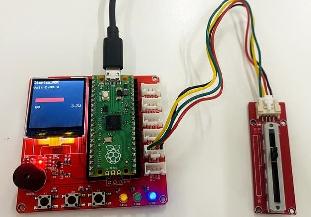
Slide the paddle of the potentiometer, and the voltage value displayed on the screen will change.
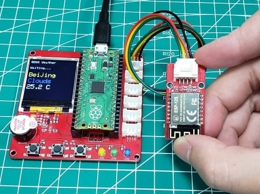
Project 4: Using ESP8266-12S Wifi Module with Pico
Connect ESP8266-12S WiFi module to the CN1 port. The ESP8266-12 connects to the Local WiFi Network and uploads/retrives data to/from the Server.

Run the test_json.py and also project-4-weather_8266.py on Thonny IDE.
Change the WiFi SSID & WiFi password in the code. Also make changes to the API. The API from “api.openweathermap.org” is not stable, please try more and pay attention to the serial port information.
In my case, I was not able to get the Weather data, but you can try. Good Luck.
There is also a detailed tutorial on creating a Web Server with Pico & ESP8266 in one of our previous post.
Project 5: Reading DHT11 Humidity Temperature Sensor Data
Connect DHT11 Sensor module to the CN6 port. The DHT11 measures temperature and Humidity data.

Run the test_dht11.py and also project-5-temperature.py on Thonny IDE.
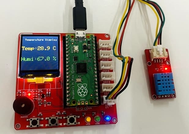
The temperature and humidity measured will be displayed on the LCD.
Project 6: Ultrasonic Range Finder with HC-SR04
Connect HC-SR04 Ultrasonic Sensor module to the CN6 port. The HC-SR04 Ultrasonic Sensor measures the distance.
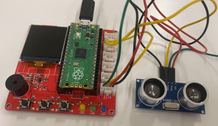
Run the test_hc-sr04.py and also project-6-HC-SR04_distance.py on Thonny IDE.

The The Ranging value will be displayed on the LCD.
Project 7: Relay + Servo Motor Control
Connect Realy module to the CN5 port & SG90 Servo Motor to CN6 port.
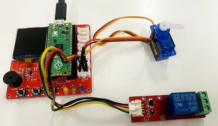
Run the test_servo.py and also project-7-servo_control.py on Thonny IDE.

- Click the K1 button to drive the Servo to O level.
- Click the K2 button to drive the Servo to 9O level.
- Click the K3 button to control the relay on/off.
Project 8: WS2812B RGB LED Control
Connect WS2812 module to the CN6 port. The WS2812B is chip-based RGB LED with the chip logic built into the LED itself.
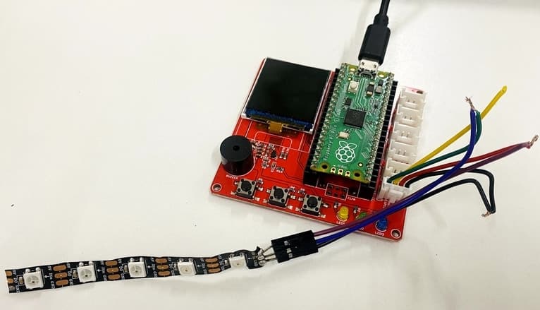
Run the project-8-ws2812.py on Thonny IDE.
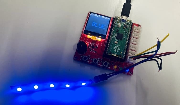
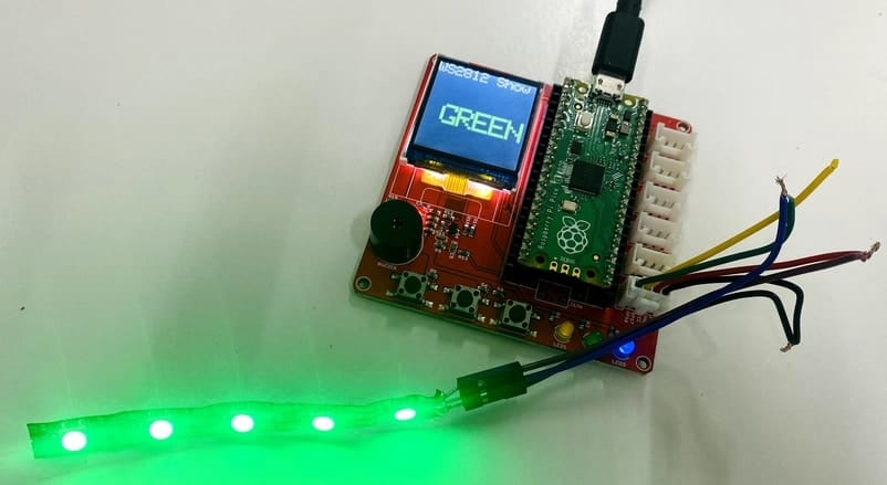

The LEDs will light on and turn different colors circularly.
Video Tutorial & Guide


1 Comment
This is absolutely a great tutorial, very useful! Thank you so much!