

Overview
In this tutorial, we will delve into the process of interfacing the ADS1115 16-Bit ADC Module with the ESP8266 microcontroller. The ADS1115 breakout board is a high-resolution analog-to-digital converter (ADC) that can be utilized with a variety of microcontrollers, such as Arduino, STM32, and ESP8266/32. The ESP8266 is a low-cost microcontroller with built-in Wi-Fi capabilities, making it a popular choice for IoT projects. However, one of its limitations is that it only has a single analog pin. By interfacing it with the ADS1115, you can expand its analog capabilities.
The ESP8266 comes with a built-in 10-bit ADC, which offers lower resolution than the 12-bit ADC found in ESP32 or the 16-bit ADC provided by the ADS1115. The ADS1115’s 16-bit resolution offers superior performance in terms of voltage measurement. The smallest voltage the ESP8266 can measure is 1V / 1024 = 0.00098V (or 0.98mV), while the ADS1115 can measure as low as 5V / 65536 = 0.000076V (76uV). This makes the ADS1115 an excellent choice when precise voltage measurements are required, and the single analog pin of the ESP8266 needs to be expanded. If you want more precison up to 0.3uV, you may check ADS1220 24-Bit ADC Module.
In the following sections of this tutorial, we will provide step-by-step instructions for connecting the ADS1115 to the ESP8266, setting up the I2C communication, and writing code to read and process analog signals using the Arduino IDE. By the end of this guide, you will have a solid understanding of how to interface the ADS1115 16-Bit ADC Module with the ESP8266 and expand its analog capabilities for your projects.
Bill of Materials
To thoroughly understand the ADS1115 ADC Module when used with NodeMCU ESP8266, we require the following components:
| S.N. | Components | Quantity | Purchase Link |
|---|---|---|---|
| 1 | NodeMCU ESP8266 Board | 1 | Amazon | AliExpress |
| 2 | ADS1115 ADC Module | 1 | Amazon | AliExpress |
| 3 | 16x2 I2C LCD Display | 1 | Amazon | AliExpress |
| 4 | 10K Potentiometer | 2 | Amazon | AliExpress |
| 5 | Breadboard | 1 | Amazon | AliExpress |
| 6 | Connecting Wires | 1 | Amazon | AliExpress |
ADC Limitations in ESP8266
The ESP8266 is a Wi-Fi enabled microcontroller that features an on-chip 10-bit analog-to-digital converter (ADC). While the ADC on the ESP8266 provides basic functionality, it does have some limitations that you should be aware of.
Here are some of the limitations of the ESP8266 ADC:
- Limited resolution: The ADC on the ESP8266 has a 10-bit resolution, which means it can detect voltage levels between 0 and 3.3 volts and divide them into 1024 levels. This resolution may not be sufficient for applications that require high-precision measurements.
- Limited input voltage range: The ADC on the ESP8266 can only measure voltages between 0 and 1V when using the default voltage reference. However, you can use an external voltage reference to measure higher voltages.
- Noise and linearity issues: The ADC on the ESP8266 can be affected by noise and non-linearities, which can result in inaccurate readings. To minimize these issues, you may need to use a low-pass filter and calibrate the ADC.
- Slow sampling rate: The ADC on the ESP8266 has a maximum sampling rate of about 77 kHz. This may not be fast enough for some applications that require real-time measurements.
- Single-ended inputs: The ADC on the ESP8266 only supports single-ended inputs. This means that you cannot measure the voltage difference between two points directly. You may need to use an external differential amplifier to measure voltage differences.
Despite these limitations, the ESP8266 ADC can be a useful tool for basic analog measurements in low-cost and low-power applications. However, for interfacing, multiple analog sensors, and high-precision measurements ESP8266 ADC fails.
ADS1115 Chip
The ADS1115 is a precision, low-power, 16-bit, I2Ccompatible, analog-to-digital converter IC.

Features of ADS1115
- 16-bit Resolution
- Four (4) Channel Single-Ended or Two (2) Channel Differential Inputs
- I2C Protocol Interface
- Programmable Comparator
- Wide Supply Range
- Low Current Consumption
- Continuous-Conversion Mode
- Programmable Data Rate
- Programmable Comparator
- Single-Cycle Settling
- Internal Low-Drift Voltage Reference
- Internal Oscillator
- Wide Operating Temperature Range
- Available in Ultra-Small X2QFN Package
ADS1115 Pin Configuration
The below image shows the pin configuration of the ADS1115 chip.

- Pin 1 is the ADDR pin that selects the I2C address for the chip.
- Pin 2 is the Alert/Ready pin which serves as a data ready and alert signal.
- Pin 3 is the GND terminal.
- Pins 4, 5, 6 & 7 are the four (4) ADC input pins. We can use these pins as either four (4) single-ended inputs or two (2) differential inputs.
- Pin 8 is the positive power supply pin which accepts 2.0 V to 5.5 V
- Pins 9 and 10 are the terminals for the I2C interface, SDA and SCL respectively.
ADS1115 Functional Block Diagram
The following presents the functional diagram for the ADS1115 Chip:

First, a multiplexer chooses the input signal. This selected signal then enters a Programmable Gain Amplifier (PGA), which can be programmed to amplify smaller signals before the conversion takes place.
Next, a 16-bit Delta Sigma converter processes the input. This converter employs its own integrated voltage reference and oscillator for input signal measurement. Once the conversion is completed, the resulting data is sent to the I2C interface. Additionally, a comparator generates a signal for the external interface, indicating that the converted result is available for retrieval.
Typical Connections of the ADS1115
The primary I2C connections for the ADS1115 can be seen in the following image.

The ADS1115 is compatible with standard mode, fast mode, and high-speed mode I2C controllers, allowing it to interface directly with them. The ADS1115 functions with any microcontroller I2C peripheral, encompassing master-only and single-master I2C peripherals.
For more information refer to ADS1115 Datasheet
ADS1115 Module or Breakout Board
The ADS1115 is available in X2QFN and VSSOP packages, which are not suitable for prototyping. As a result, an ADS1115 Module or Breakout Board is necessary for use with ESP8266 or any other microcontroller.

These modules can be found by various manufacturers at affordable prices. Their breadboard-friendly design makes them ideal for prototyping and testing applications, allowing for easy integration.
ADS1115 Module Pinout
The ADS1115 Module has a total number of 10 Pins.
| Pin. No. | Pin Name | Pin Description |
| 1 | VDD | Power supply: 2.0V to 5.5V |
| 2 | GND | Ground |
| 3 | SCL | Serial clock input: Clocks data on SDA (used for I2C communication) |
| 4 | SDA | Serial data: Transmits and receives data (used for I2C communication) |
| 5 | ADDR | I2C address select (slave) |
| 6 | ALERT/RDY | Digital comparator output or conversion ready |
| 7 | AIN0 | Differential channel 1: Single-ended channel 1 input or Negative input |
| 8 | AIN1 | Differential channel 1: Single-ended channel 2 input or Negative input |
| 9 | AIN2 | Differential channel 2: Single-ended channel 3 input or Positive input |
| 10 | AIN3 | Differential channel 2: Single-ended channel 4 input or Negative input |
ADS1115 Module Schematic
The illustration displayed earlier represents Adafruit’s adaptation of the ADS1115 module.

This design adheres to the standard connection protocol for the ADS1115 chip. It features 10K ohm pull-up resistors on both the I2C and Alert pins, as well as a 1uF capacitor situated between the VDD and GND pins, functioning as a decoupling capacitor.
Interfacing ADS1115 Module with ESP8266
The ESP8266 wiring diagram for interfacing the ADS1115 ADC Module is simple and straightforward.

To get started, connect the VDD and GND pins of the ADS1115 module to the 3.3V and GND pins of the ESP8266 respectively. Then, connect the ADS1115 I2C pins (SDA and SCL) to the I2C pins (SDA=D2 and SCL=D1) of the ESP8266. The ADDR pin of the chip should be connected to either VDD, SDA, or SCL, depending on which of the addresses 0x49, 0x4A, or 0x4B you want to use. Note that the ADDR pin is pulled down to the GND by default with a 10K resistor.
If you want to use the ALERT/READY pin of the ADS1115 module, you should connect it to a digital pin of the ESP8266. This pin serves two purposes. Firstly, you can use it for interrupt-driven conversion where it serves as a data READY signal. Secondly, you can use it with the programmable output comparator for detecting conversion thresholds. In this case, it serves as an ALERT signal.
The ADS1115 has four ADC outputs, A0, A1, A2, and A3, which means that you can connect up to four analog sensors to this module. To test the module reading, you can use a potentiometer, which you should connect according to the circuit diagram provided above.
ADS1115 Library Installation
There are multiple libraries available for the ADS1115 Module. While browsing through the Library Manager you will get the library from a different developer.

Out of all the available libraries, we can try using one of the stable libraries for our application. The library is from Adafruit. You can download the library from the following link as well.
The library has the functionality to set the I2C clock speed, set Programmable Gain, Operational mode & Data rate. Using this library we can read the sensor ADC Data in Single mode, Differential Mode, and Continuous Mode.
Basic Source Code/Program
With the hardware connections complete, it’s time to set up the I2C communication and write code to read and process analog signals using the Arduino IDE. Using the basic example code from the Adafruit ADS1115 example folder, we can test the working of the sensor with NodeMCU ESP8266.
Copy the following code and upload it to the NodeMCU ESP8266 Board.
|
1 2 3 4 5 6 7 8 9 10 11 12 13 14 15 16 17 18 19 20 21 22 23 24 25 26 27 28 29 30 31 32 33 34 35 36 37 38 39 40 41 42 43 44 45 46 47 48 49 50 51 |
#include <Adafruit_ADS1X15.h> Adafruit_ADS1115 ads; /* Use this for the 16-bit version */ //Adafruit_ADS1015 ads; /* Use this for the 12-bit version */ void setup(void) { Serial.begin(115200); Serial.println("Getting single-ended readings from AIN0..3"); Serial.println("ADC Range: +/- 6.144V (1 bit = 3mV/ADS1015, 0.1875mV/ADS1115)"); // The ADC input range (or gain) can be changed via the following // functions, but be careful never to exceed VDD +0.3V max, or to // exceed the upper and lower limits if you adjust the input range! // Setting these values incorrectly may destroy your ADC! // ADS1015 ADS1115 // ------- ------- // ads.setGain(GAIN_TWOTHIRDS); // 2/3x gain +/- 6.144V 1 bit = 3mV 0.1875mV (default) // ads.setGain(GAIN_ONE); // 1x gain +/- 4.096V 1 bit = 2mV 0.125mV //ads.setGain(GAIN_TWO); // 2x gain +/- 2.048V 1 bit = 1mV 0.0625mV // ads.setGain(GAIN_FOUR); // 4x gain +/- 1.024V 1 bit = 0.5mV 0.03125mV // ads.setGain(GAIN_EIGHT); // 8x gain +/- 0.512V 1 bit = 0.25mV 0.015625mV // ads.setGain(GAIN_SIXTEEN); // 16x gain +/- 0.256V 1 bit = 0.125mV 0.0078125mV if (!ads.begin()) { Serial.println("Failed to initialize ADS."); while (1); } } void loop(void) { int16_t adc0, adc1, adc2, adc3; float volts0, volts1, volts2, volts3; adc0 = ads.readADC_SingleEnded(0); adc1 = ads.readADC_SingleEnded(1); adc2 = ads.readADC_SingleEnded(2); adc3 = ads.readADC_SingleEnded(3); volts0 = ads.computeVolts(adc0); volts1 = ads.computeVolts(adc1); volts2 = ads.computeVolts(adc2); volts3 = ads.computeVolts(adc3); Serial.println("-----------------------------------------------------------"); Serial.print("AIN0: "); Serial.print(adc0); Serial.print(" "); Serial.print(volts0); Serial.println("V"); Serial.print("AIN1: "); Serial.print(adc1); Serial.print(" "); Serial.print(volts1); Serial.println("V"); Serial.print("AIN2: "); Serial.print(adc2); Serial.print(" "); Serial.print(volts2); Serial.println("V"); Serial.print("AIN3: "); Serial.print(adc3); Serial.print(" "); Serial.print(volts3); Serial.println("V"); } |
After uploading the code, open the Serial Monitor. The Serial Monitor will show the ADC value for all 4 outputs AIN0, AIN1, AIN2, and AIN3 along with the output voltage.

Since we have only used two potentiometers for AIN0 and AIN1, we will get these values changing while rotating the potentiometer.
Testing ADS1115 Module Accuracy
Let’s check how accurate the ADS1115 ADC Module is. To do this, we can use an LCD Display to show us the ADC value and the measured voltages. Then, we can use a multimeter to measure the detected voltage and compare it to the voltage displayed on the Serial Monitor.
ADS1115, ESP8266 & LCD Connection Diagram
Connect the LCD to the previous circuit as per the circuit diagram.

Connect the LCD SDA & SCL Pin to D2 & D1 of ESP8266 respectively. Provide 5V VCC & GND connection to LCD Display using Vin & GND pins of ESP8266.

Source Code/Program
The code requires I2C LCD Library for compilation. Then you can copy the following code and upload it to the ESP8266 Board.
|
1 2 3 4 5 6 7 8 9 10 11 12 13 14 15 16 17 18 19 20 21 22 23 24 25 26 27 28 29 30 31 32 33 34 35 36 37 38 39 40 41 42 43 44 45 46 47 48 49 50 51 52 53 54 55 56 57 58 59 60 61 62 63 64 65 66 67 68 69 70 71 72 |
#include <Adafruit_ADS1X15.h> #include <LiquidCrystal_I2C.h> LiquidCrystal_I2C lcd(0x27, 16, 2); Adafruit_ADS1115 ads; /* Use this for the 16-bit version */ //Adafruit_ADS1015 ads; /* Use this for the 12-bit version */ void setup(void) { Serial.begin(115200); Serial.println("Getting single-ended readings from AIN0..3"); Serial.println("ADC Range: +/- 6.144V (1 bit = 3mV/ADS1015, 0.1875mV/ADS1115)"); // The ADC input range (or gain) can be changed via the following // functions, but be careful never to exceed VDD +0.3V max, or to // exceed the upper and lower limits if you adjust the input range! // Setting these values incorrectly may destroy your ADC! // ADS1015 ADS1115 // ------- ------- // ads.setGain(GAIN_TWOTHIRDS); // 2/3x gain +/- 6.144V 1 bit = 3mV 0.1875mV (default) // ads.setGain(GAIN_ONE); // 1x gain +/- 4.096V 1 bit = 2mV 0.125mV //ads.setGain(GAIN_TWO); // 2x gain +/- 2.048V 1 bit = 1mV 0.0625mV // ads.setGain(GAIN_FOUR); // 4x gain +/- 1.024V 1 bit = 0.5mV 0.03125mV // ads.setGain(GAIN_EIGHT); // 8x gain +/- 0.512V 1 bit = 0.25mV 0.015625mV // ads.setGain(GAIN_SIXTEEN); // 16x gain +/- 0.256V 1 bit = 0.125mV 0.0078125mV lcd.init(); lcd.backlight(); if (!ads.begin()) { Serial.println("Failed to initialize ADS."); while (1); } } void loop(void) { int16_t adc0, adc1, adc2, adc3; float volts0, volts1, volts2, volts3; adc0 = ads.readADC_SingleEnded(0); adc1 = ads.readADC_SingleEnded(1); adc2 = ads.readADC_SingleEnded(2); adc3 = ads.readADC_SingleEnded(3); volts0 = ads.computeVolts(adc0); volts1 = ads.computeVolts(adc1); volts2 = ads.computeVolts(adc2); volts3 = ads.computeVolts(adc3); Serial.println("-----------------------------------------------------------"); Serial.print("AIN0: "); Serial.print(adc0); Serial.print(" "); Serial.print(volts0); Serial.println("V"); Serial.print("AIN1: "); Serial.print(adc1); Serial.print(" "); Serial.print(volts1); Serial.println("V"); Serial.print("AIN2: "); Serial.print(adc2); Serial.print(" "); Serial.print(volts2); Serial.println("V"); Serial.print("AIN3: "); Serial.print(adc3); Serial.print(" "); Serial.print(volts3); Serial.println("V"); lcd.clear(); lcd.setCursor(0, 0); lcd.print("ADC0:"); lcd.print(adc0); lcd.print(" "); lcd.print(volts0); lcd.print("V"); lcd.setCursor(0, 1); lcd.print("ADC1:"); lcd.print(adc1); lcd.print(" "); lcd.print(volts1); lcd.print("V"); delay(1000); } |
Test Results
Upon uploading the code, the module becomes prepared for testing. A multimeter will be required for this purpose.
The LCD will display the ADC Value and measured Voltage.

We are using two potentiometers to input ADC Voltage and display both of them on LCD Display. One of the measured voltages shown by the multimeter is 3.14V which in LCD shows 3.17V.
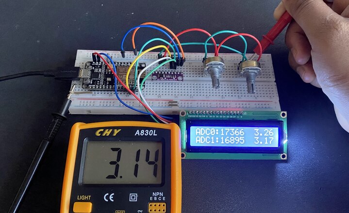
The maximum ADC output voltage from the module is 3.3V and the minimum is 0V.
While measuring lower voltage, at 0.13V in LCD was measured as 0.12V in Multimeter.
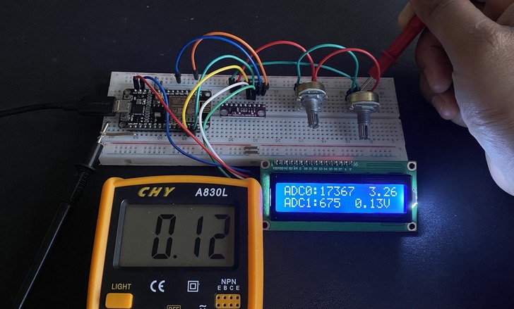
According to other tests, this device has a stated typical accuracy of 0.01% but it has a maximum accuracy of 0.15%. This accuracy includes all sources of error such as voltage reference, Gain error, offset, and noise.
Interfacing the ADS1115 with the ESP8266 not only enhances the precision of voltage measurements but also expands the limited analog capabilities of the ESP8266. By following this tutorial, you can successfully integrate the ADS1115 16-Bit ADC Module with the ESP8266 and leverage its full potential for your IoT projects.
Video Tutorial & Guide

The same ADS1115 Module can also be used with other Microcontrollers which are as follows:


")

