Close Menu
  • Articles
    • Learn Electronics
    • Product Review
    • Tech Articles
  • Electronics Circuits
    • 555 Timer Projects
    • Op-Amp Circuits
    • Power Electronics
  • Microcontrollers
    • Arduino Projects
    • STM32 Projects
    • AMB82-Mini IoT AI Camera
    • BLE Projects
  • IoT Projects
    • ESP8266 Projects
    • ESP32 Projects
    • ESP32 MicroPython
    • ESP32-CAM Projects
    • LoRa/LoRaWAN Projects
  • Raspberry Pi
    • Raspberry Pi Projects
    • Raspberry Pi Pico Projects
    • Raspberry Pi Pico W Projects
  • Electronics Calculator
Facebook X (Twitter) Instagram
  • About Us
  • Disclaimer
  • Privacy Policy
  • Contact Us
  • Advertise With Us
Facebook X (Twitter) Instagram Pinterest YouTube LinkedIn
How To Electronics
  • Articles
    • Learn Electronics
    • Product Review
    • Tech Articles
  • Electronics Circuits
    • 555 Timer Projects
    • Op-Amp Circuits
    • Power Electronics
  • Microcontrollers
    • Arduino Projects
    • STM32 Projects
    • AMB82-Mini IoT AI Camera
    • BLE Projects
  • IoT Projects
    • ESP8266 Projects
    • ESP32 Projects
    • ESP32 MicroPython
    • ESP32-CAM Projects
    • LoRa/LoRaWAN Projects
  • Raspberry Pi
    • Raspberry Pi Projects
    • Raspberry Pi Pico Projects
    • Raspberry Pi Pico W Projects
  • Electronics Calculator
How To Electronics
Home » DIY Function Generator using XR2206 Kit : 1Hz-1MHz
Electronics Circuits

DIY Function Generator using XR2206 Kit : 1Hz-1MHz

Mamtaz AlamBy Mamtaz AlamUpdated:April 2, 20235 Mins Read
Share Facebook Twitter LinkedIn Telegram Reddit WhatsApp
DIY Function Generator using XR2206 Kit 1Hz-1MHz
Share
Facebook Twitter LinkedIn Pinterest Email Reddit Telegram WhatsApp

Overview

A function generator is essential for electronics labs, but its high cost can be prohibitive for many hobbyists. There are numerous DIY designs available, with the most popular and affordable Chinese kit featuring the XR2206 function generator chip. From my experience, the easy-to-assemble 1Hz-1MHz XR2206 kit enables various standard measurements and experiments while providing reasonably stable and accurate waveforms. It’s more than sufficient for a modest home electronics hobby lab!

XR2206 Function Generator Kit

The XR2206 Function Generator Kit is a user-friendly DIY kit for constructing a frequency generator that creates sine, triangle, and square waveforms with frequencies between 1Hz and 1MHz. This guide will help you assemble and use the XR2206 Function Generator Kit effectively.


Components Required

  1. XR2206 Function Generator Kit (includes the XR2206 IC, PCB, and other components like resistors, capacitors, and potentiometers)
  2. 9V or 12V DC power supply
  3. Oscilloscope
  4. Soldering iron and solder
  5. Wire cutter and stripper
  6. Jumper wires and/or BNC connectors for output


XR2206 IC

The XR-2206 is a single-chip function generator capable of producing high-quality and stable sine, square, triangle, ramp, and pulse waveforms with great accuracy. These output waveforms can be modulated in both amplitude and frequency by an external voltage.

XR2206 IC

Its operational frequency ranges from 0.01Hz to over 1MHz, making it ideal for communications, instrumentation, and function generator applications that require sinusoidal tones, AM, FM, or FSK generation. The XR-2206 has a typical drift specification of 20ppm/°C, and its oscillator frequency can be linearly swept across a 2000:1 range using an external control voltage while maintaining low distortion.

Download: XR2206 Datasheet


Features

  • Low-Sine Wave Distortion, 0.5%, Typical
  • Excellent Temperature Stability, 20ppm/°C, Typ.
  • Wide Sweep Range, 2000:1, Typical
  • Low-Supply Sensitivity, 0.01%V, Typ.
  • Linear Amplitude Modulation
  • TTL Compatible FSK Controls
  • Wide Supply Range, 10V to 26V
  • Adjustable Duty Cycle, 1% TO 99%

Applications

  • Waveform Generation
  • Sweep Generation
  • AM/FM Generation
  • V/F Conversion
  • FSK Generation
  • Phase-Locked Loops (VCO)


XR2206 Function Generator Kit Assembly

Upon purchasing the DIY kit, some soldering work is necessary, but it includes all components required for the project.

The kit features through-hole components, and the double-sided PCB is marked with legends that clearly indicate where to mount and solder each part. Furthermore, the kit provides a high-quality socket for the XR2206 chip, stylish caps for the jumpers, and knobs for the potentiometers.


Circuit Diagram

XR2206 Function Generator Kit Circuit


Soldering Tips

  1. Solder the components on top of the board in order of height, starting with the lowest components such as capacitors, resistors, and diodes.
  2. Proceed to solder the IC socket, terminal blocks, and finally the power socket and adjustable potentiometers.
  3. Use diagonal cutting pliers to trim the excess pins on the back of the board as closely as possible.


Soldering Process

  1. Begin by identifying all components included in the kit. You should have the XR2206 IC, a printed circuit board (PCB), resistors, capacitors, potentiometers, and other necessary components.
  2. Solder the resistors, capacitors, and other small components onto the PCB, paying close attention to their values and orientations. Use the kit’s provided schematic or assembly guide as a reference.
  3. Solder the XR2206 IC socket onto the PCB, ensuring that the notch or dot on the socket aligns with the marking on the PCB. This will help you correctly insert the XR2206 IC later.
  4. Insert the XR2206 IC into the socket, aligning the notch or dot on the IC with the marking on the socket. Press down gently to ensure proper seating.
  5. Solder the potentiometers for frequency and amplitude control onto the PCB. These will allow you to adjust the output frequency and amplitude of the waveforms.
  6. Attach a power connector or solder wires directly to the PCB for the power supply input. Make sure to connect the positive and negative terminals correctly.
  7. Connect the output to a BNC connector or solder wires for connecting the output to an oscilloscope or other testing equipment.


Testing and Usage

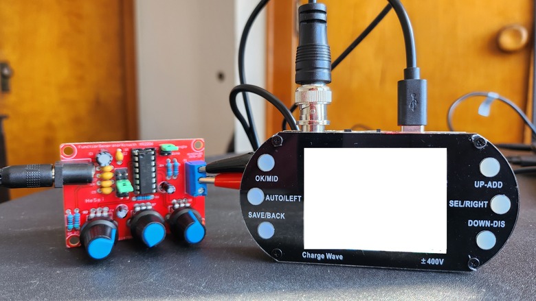
Connect the power supply to the XR2206 Function Generator. Be sure to use a 9V or 12V DC power supply as specified by the kit.

Connect the output to an oscilloscope or other testing equipment using jumper wires or a BNC connector. In this testing part, I am using a simple portable oscilloscope. If you don’t have an Oscilloscope, you can you make your own DIY Oscilloscope using Raspberry Pi Pico & Smartphone.

Turn on the power supply and adjust the potentiometers to select the desired waveform, frequency, and amplitude.

XR2206 Function Generator Waveform

Observe the output on the oscilloscope, and fine-tune the potentiometers as needed to achieve the desired waveform and frequency range. Using the following setting you can generate various waveforms and change the settings.

S.N. Operation Function
1 Short Jumper J1 SIN/TRI port output sine wave
2 Short J2 Jumper SIN/TRI port output triangular wave
3 SQU port output square wave
4 AMP tune Tune the amplitude of triangular wave/sine wave
5 Fine tune Fine tune the frequency of square wave/triangular wave/ sine wave (select different gear through Jumper Cap)
6 Coarse tune Coarse tune the frequency of square wave/triangular wave/sine wave(select different gear through Jumper Cap)

Waveform Specifications

  1. Sine Wave
  • Amplitude: 0-3V with 9V DC input
  • Distortion: Less than 1% (at 1kHz)
  • Flatness: +0.05dB from 1Hz to 100kHz

2. Square Wave

  • Amplitude: 8V (without load) with 9V DC input
  • Rise Time: Less than 50ns (at 1kHz)
  • Fall Time: Less than 30ns (at 1kHz)
  • Symmetry: Less than 5% (at 1kHz)

3. Triangle Wave

  • Amplitude: 0-3V with 9V DC input
  • Linearity: Less than 1% (up to 100kHz) at 10mA


Output Waveforms

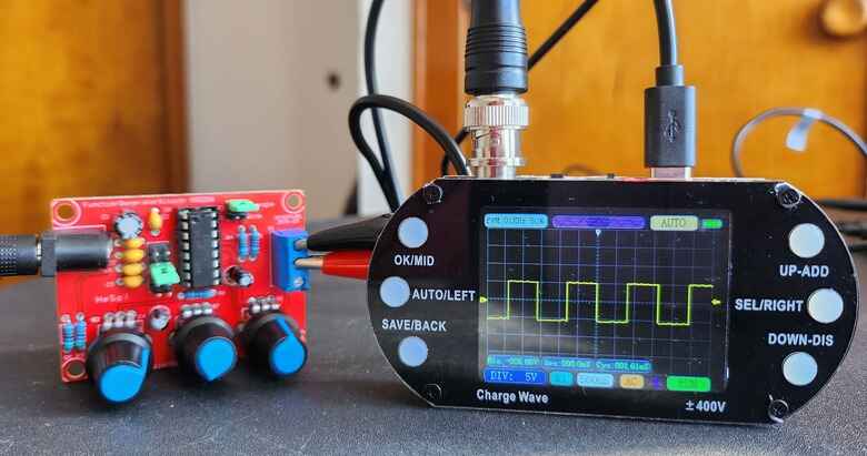
The square wave looks like this.

XR2206 Function Generator

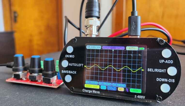
The sine wave can be tuned to form perfect wave.

XR2206 Function Generator

You can also produce triangular waveform.

XR2206 Function Generator

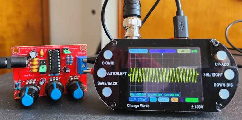
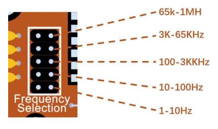
The frequency selection jumper can be adjusted as follows to generate different frequencies.

Once you have achieved the desired output, you can use the function generator in various applications, such as testing electronic circuits or audio equipment.

Share. Facebook Twitter Pinterest LinkedIn Tumblr Email Reddit Telegram WhatsApp
Previous ArticleDIY Thermal Camera with ESP8266 & AMG8833 Thermal Image Sensor
Next Article Negative Voltage Generator Circuit using 555 Timer IC

Related Posts

Water Level Alert using Float Sensor & 555 Timer

Water Level Alert using Float Sensor & 555 Timer

2K
Adjustable Auto On Off Delay Timer Circuit Using 555 IC

555 Based Adjustable Auto On Off Delay Timer Circuit

Updated:February 14, 20252K

12V DC to 220V AC Inverter Circuit & PCB

Updated:February 2, 20251461K
DIY Smart Blind Stick using Op-Amp & IR Sensor

DIY Smart Blind Stick using Op-Amp & IR Sensor

Updated:February 2, 202515K
Square Wave Generator Circuit with Op Amp IC LM358

Square Wave Generator Circuit with Op Amp IC LM358

Updated:February 2, 202513K
Gas Leak Detection & Alarm using 555 Timer IC

Gas Leak Detection & Alarm using 555 Timer IC

Updated:February 2, 202525K
Add A Comment

CommentsCancel reply

Latest Posts
ESP32 Fingerprint Attendance System with Live Web Dashboard

ESP32 Fingerprint Attendance System with Live Web Dashboard

June 16, 2026
IoT Based PM & Air Quality Monitoring System using ESP32

IoT Based PM & Air Quality Monitoring System using ESP32

June 14, 2026
DIY ESP32 MLX90640 IR Thermal Camera with Live Web Display

DIY ESP32 MLX90640 IR Thermal Camera with Live Web Display

May 10, 2026
IoT Activity Tracker with ESP32 & Accelerometer Gyroscope

IoT Activity Tracker with ESP32 & Accelerometer/Gyroscope

May 2, 2026
A Guide to Sourcing Obsolete ICs for Vintage Projects

Beyond AliExpress: A Guide to Sourcing Obsolete ICs for Vintage Projects

April 21, 2026

ESP32 IoT Vehicle Motion Analyzer with MPU6050 & LIS3MDL

April 27, 2026
Building a Smart Sensor Node with a BLE Microcontroller

Building a Smart Sensor Node with a BLE Microcontroller

February 26, 2026
High-Accuracy Pitch, Roll, Yaw with ESP32 & BNO08x IMU

High-Accuracy Pitch, Roll, Yaw with ESP32 & BNO08x IMU

April 27, 2026
Top Posts & Pages
  • IoT Based PM & Air Quality Monitoring System using ESP32
    IoT Based PM & Air Quality Monitoring System using ESP32
  • How to use LDR Sensor Module with Arduino
    How to use LDR Sensor Module with Arduino
  • 12V DC to 220V AC Inverter Circuit & PCB
    12V DC to 220V AC Inverter Circuit & PCB
  • Buck Converter: Basics, Working, Design & Application
    Buck Converter: Basics, Working, Design & Application
  • IoT AC Energy Meter with PZEM-004T & ESP32 WebServer
    IoT AC Energy Meter with PZEM-004T & ESP32 WebServer
  • How to use Modbus RTU with ESP32 to read Sensor Data
    How to use Modbus RTU with ESP32 to read Sensor Data
  • ECG Graph Monitoring with AD8232 ECG Sensor & Arduino
    ECG Graph Monitoring with AD8232 ECG Sensor & Arduino
  • Silicon Controlled Rectifier (SCR): Construction, Working & Applications
    Silicon Controlled Rectifier (SCR): Construction, Working & Applications
Categories
  • Arduino Projects (197)
  • Articles (60)
    • Learn Electronics (19)
    • Product Review (15)
    • Tech Articles (28)
  • Electronics Circuits (46)
    • 555 Timer Projects (21)
    • Op-Amp Circuits (7)
    • Power Electronics (13)
  • IoT Projects (205)
    • ESP32 MicroPython (7)
    • ESP32 Projects (82)
    • ESP32-CAM Projects (15)
    • ESP8266 Projects (76)
    • LoRa/LoRaWAN Projects (22)
  • Microcontrollers (38)
    • AMB82-Mini IoT AI Camera (4)
    • BLE Projects (18)
    • STM32 Projects (19)
  • Raspberry Pi (93)
    • Raspberry Pi Pico Projects (57)
    • Raspberry Pi Pico W Projects (12)
    • Raspberry Pi Projects (24)
Follow Us
  • Facebook
  • Twitter
  • Pinterest
  • Instagram
  • YouTube
About Us

“‘How to Electronics’ is a vibrant community for electronics enthusiasts and professionals. We deliver latest insights in areas such as Embedded Systems, Power Electronics, AI, IoT, and Robotics. Our goal is to stimulate innovation and provide practical solutions for students, organizations, and industries. Join us to transform learning into a joyful journey of discovery and innovation.

Copyright © How To Electronics. All rights reserved.
  • About Us
  • Disclaimer
  • Privacy Policy
  • Contact Us
  • Advertise With Us

Type above and press Enter to search. Press Esc to cancel.

Ad Blocker Enabled!
Ad Blocker Enabled!
Looks like you're using an ad blocker. Please allow ads on our site. We rely on advertising to help fund our site.