

Overview
In this project, we’ll make our own Thermal Camera using the ESP8266 and the AMG8833 8×8 Thermal Image Array Temperature Sensor. We’ll visualize the thermal image on an ILI9341 screen. This homemade DIY Thermal Camera is portable because it works with a 3.7V Lithium-Ion battery. You can recharge the battery with a 5V Micro-USB cable, as it has a special Battery charging module called TP4056.
Earlier we build DIY Thermal Imaging Camera using Raspberry Pi and 7 inch LCD Display, but the solution was very expensive.
Thermal cameras have a wide range of applications, such as identifying temperature irregularities, assessing thermal performance, and even taking thermal images. Unfortunately, these cameras can be quite costly, and not everyone can afford them. What if you could construct your own thermal camera using inexpensive components like the ESP8266 and AMG8833 thermal image array temperature sensor? This is the focus of this article!
Building a thermal camera with the ESP8266 and the AMG8833 thermal image array temperature sensor is an enjoyable and budget-friendly project that can be accomplished by anyone with basic electronics knowledge. Whether you want to observe temperature anomalies in your home, locate heat leaks in your walls, or Detect Fever, or just take thermal photographs, this project is an excellent starting point. So, let’s dive in!.
Bill of Materials
We need the following components for this project. You can purchase the components from the given links.

| S.N. | Components | Quantity | Purchase Link |
|---|---|---|---|
| 1 | NodeMCU ESP8266 WiFi Module | 1 | Amazon | AliExpress |
| 2 | AMG8833 Thermal Image Sensor | 1 | Amazon | AliExpress |
| 3 | ILI9341 2.8" TFT LCD Display | 1 | Amazon | AliExpress |
| 4 | TP4056 Battery Charging Module | 1 | Amazon | AliExpress |
| 5 | 3-Pin Slide Switch | 1 | Amazon | AliExpress |
| 6 | Resistor 130K | 1 | Amazon | AliExpress |
| 7 | 3.7V Lithium-Ion Battery | 1 | Amazon | AliExpress |
What is Thermal Imaging Camera & how they work?
A thermal imaging camera is a device that detects and displays temperature patterns in the form of an image.

It works by measuring the infrared radiation emitted by objects and translating that information into a visual image that shows relative differences in temperature. This allows you to see objects, structures, and areas that may be too hot or cold and identify issues that could not be seen with the naked eye.

Thermal imaging cameras work by detecting the infrared radiation emitted by objects and translating that information into a visual image. Here’s how the process works in detail:
- Infrared detection: The camera’s sensor, either a thermopile or a microbolometer, detects the infrared radiation emitted by objects in its field of view. The amount of radiation detected depends on the temperature of the object.
- Conversion to electrical signal: The sensor converts the detected infrared radiation into a measurable electrical signal. This signal is proportional to the temperature of the object and is used to create the thermal image.
- Image processing: The electrical signal is processed by the camera’s image processor, which translates the signal into an image that displays relative differences in temperature. The image processor also enhances the image by applying various filters, such as color palettes and brightness and contrast adjustments, to make the thermal information more easily understood.
- Display: The final thermal image is displayed on the camera’s screen, where you can see the temperature patterns of objects in the image. The hotter the object, the brighter it appears in the image.
AMG8833 8×8 IR Thermal Camera Sensor
AMG8833 is a simple thermal camera module from Panasonic, also known as a temperature monitoring device. It divides captured data into 64 blocks of 8×8, giving it a resolution of 8×8 or 64 pixels. Each pixel acts as an individual IR sensor, providing a separate temperature measurement, making this sensor better than PIR and pyrometric sensors that only offer one temperature value.

The AMG8833 features a built-in lens that restricts its viewing angle to 60 degrees, making it ideal for detecting objects in the mid-field. It operates at a voltage of 3.3V or 5V, with a sample rate of 1Hz to 10Hz. Its temperature resolution is approximately 0.25°C and it can detect temperatures within a range of 0°C to 80°C.

Compared to visible imaging cameras, the AMG8833 has a narrow field of view (60×60 sq. deg) and a low resolution of 64 pixels, but is costlier, at around $40-50. On the other hand, a Raspberry Pi camera with a 5MPx resolution, which is 100 times more, costs only $10-15.
The cost of thermal cameras is mainly due to the lens and circuitry, as they detect IR waves of 8-14um, which requires expensive materials like germanium or chalcogenides to be used. Additionally, extra care has to be taken to prevent camera temperature from affecting readings, making it a radiometric thermal camera. The size and heat dissipation of the camera array also add to the cost.
However, with advancements in materials and techniques, thermal cameras have become more affordable and user-friendly, and are available as I2C sensors or USB cameras.
AMG8833 Features & Specifications
- Infrared thermal imaging sensor with an 8×8 array of thermopiles
- Detects temperature differences as small as 0.01°C
- Digital output with I2C interface
- Supports up to 64 temperature measurements
- Operating temperature range: -40°C to +85°C
- Supply voltage: 2.7 V to 3.3 V
- Operating current: 120 mA
- Resolution: 8×8 pixels
- Field of view: 55° (H) x 55° (V)
- Operating temperature range: -40°C to +85°C
- Frame rate: 10 frames per second
AMG8833 Pinout
The AMG8833 infrared thermal imaging sensor has 6 pins:

- VIN: Power supply voltage input (2.7V to 3.3V)
- GND: Ground
- SCL: I2C clock line
- SDA: I2C data line
- INT: Interrupt output (active low)
- AD0: I2C address selection pin (low for 0x69, high for 0x68)
DIY Thermal Camera Circuit & Hardware
Now lets build DIY Thermal Camera using AMG8833 & ESP8266. First we need to take a look at the schematic for this project.

The AMG8833 Thermal image sensor is an I2C Module which requires I2C Pins for communication. Therefore connect the AMG8833 SDA, SCL, VCC, and GND Pin to ESP8266 D2, D1, 3.3V, and GND Pin respectively.
The ILI9341 TFT LCD Display is an SPI Module. Hence it requires SPI Connection with NodeMCU ESP8266 Board. The connection between ILI9341 & ESP8266 is as follows.
| ESP8266 Pins | ILI9341 Pins |
|---|---|
| 3.3V | VCC |
| GND | GND |
| D0 | T_IRQ |
| D3 | RST |
| D4 | D/C |
| D5 | SCK |
| D6 | CS |
| D7 | SDI |
| 3.3V | LED |

To power the entire circuit you can use 3.7V 1000mAh Lithium-Ion Battery. There is a 3-pin Slide Switch that connects/disconnects the Battery Power. To charge the battery, we can use a TP4056 Lithium-Ion Battery. In order to measure battery voltage we have fed the battery voltage to analog pin A0 of ESP8266 via a 130K resistor.
Schematic, PCB, 3D Casing & Hardware Assembly
The components assembled on breadboard looks so messy and isn’t portable. Hence we need to design a PCB and casing so that we have a portable device.

PCB Design, Gerber File, BOM File & Ordering PCB Online
If you don’t want to assemble the circuit on a zero PCB or a breadboard and you want PCB for the project, then here is the PCB for you. I used EasyEDA to draw the schematic first. The schematic has been designed with the reference of Battery Powered ESP8266 Board designed in one of our old projects.

Then I converted the schematic to PCB. The PCB Board for this project looks something like below.

The Gerber File for the PCB is given below. You can simply download the Gerber File and order the PCB from ALLPCB at 1$ only.

You can now upload the Gerber File by choosing the Quote Now option. From these options, you can choose the Material Type, Dimensions, Quantity, Thickness, Solder Mask Color and other required parameters.

After filling all details, select your country and shipping method. Finally you can place the order.
The front side and the backside of the PCB looks something like this.


You can assemble the components on the PCB. The AMG8833 Thermal Camera and ILI9341 TFT LCD Display can be connected to the PCB using the jumper wires. The BOM File can be downloaded from the following links.
3D Casing Design
The assembled PCB, AMG8833, ILI9341 LCD Display & Battery needs to be packed in a 3D Casing. Therefore you can use some ready made casing for this project.
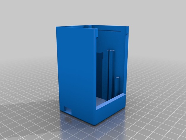
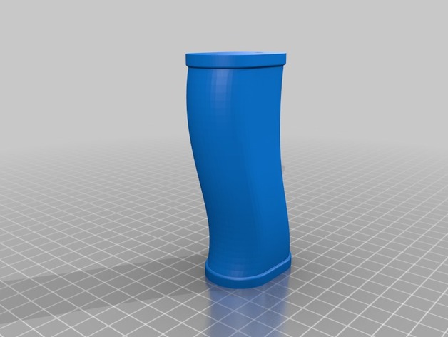
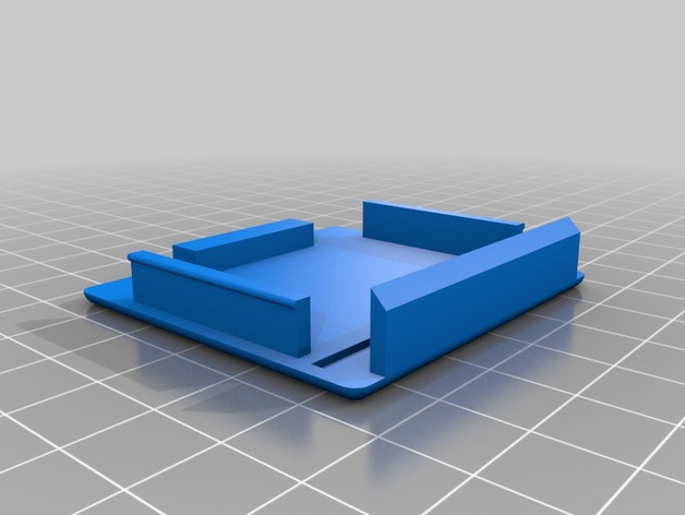
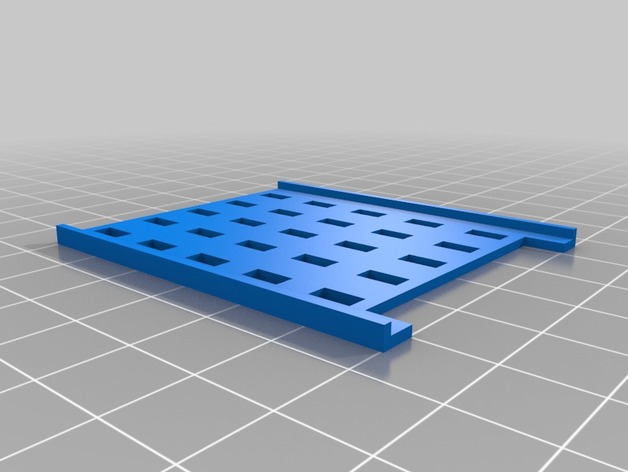
- The grip is attached to the body by two M4 screws which can be inserted directly into the PLA. The lens hole points to the front.
- The lipo, the loading circuit, and the used microcontroller are mounted with wire strips to the holder with the USB connectors facing to the top for easy loading and flashing. Why wire strips? By this, all different Lipo, loader PCB, and different µC controllers could be used
- Installation of switch in the housing, it could be glued or screwed
- Wiring everything up
- The amg8833, the display, and the electronics are inserted in the corresponding position
- The top is simply clipped in place and could be opened to update the software or to load the lipo
Source Code/Program
Let us take a look at the DIY Thermal Camera code. The code for ESP8266 & AMG8833 Thermal Camera is written in Arduino IDE.
The code requires the following libraries for compilation.
- Adafruit GFX Library: https://github.com/adafruit/Adafruit-GFX-Library
- Adafruit ILI9341 Library: https://github.com/adafruit/Adafruit_ILI9341
- TFT eSPI Library: https://github.com/Bodmer/TFT_eSPI
- AMG8833 Library: https://github.com/adafruit/Adafruit_AMG88xx
Copy the following code and upload the code to the ESP8266 Board.
|
1 2 3 4 5 6 7 8 9 10 11 12 13 14 15 16 17 18 19 20 21 22 23 24 25 26 27 28 29 30 31 32 33 34 35 36 37 38 39 40 41 42 43 44 45 46 47 48 49 50 51 52 53 54 55 56 57 58 59 60 61 62 63 64 65 66 67 68 69 70 71 72 73 74 75 76 77 78 79 80 81 82 83 84 85 86 87 88 89 90 91 92 93 94 95 96 97 98 99 100 101 102 103 104 105 106 107 108 109 110 111 112 113 114 115 116 117 118 119 120 121 122 123 124 125 126 127 128 129 130 131 132 133 134 135 136 137 138 139 140 141 142 143 144 145 146 147 148 149 150 151 152 153 154 155 156 157 158 159 160 161 162 163 164 165 166 167 168 169 170 171 172 173 174 175 176 177 178 179 180 181 182 183 184 185 186 187 188 189 190 191 192 193 194 195 196 197 198 199 200 201 202 203 204 205 206 207 208 209 210 211 212 213 214 215 216 217 218 219 220 221 222 223 224 225 226 227 228 229 230 231 232 233 234 235 236 237 238 239 240 241 242 243 244 245 246 247 248 249 250 251 252 253 254 255 256 257 258 259 260 261 262 263 264 265 266 267 268 269 270 271 272 273 274 275 276 277 278 279 280 281 282 283 284 285 286 287 288 289 290 291 292 293 294 295 296 297 298 299 300 301 302 303 304 305 306 307 308 309 310 311 312 313 314 315 316 317 318 319 320 321 322 323 324 325 326 327 328 329 330 331 332 333 334 335 336 337 338 339 340 341 342 343 344 345 346 347 348 349 350 351 352 353 354 355 356 357 358 359 360 361 362 363 364 365 366 367 368 369 370 371 372 373 374 375 376 377 378 379 380 381 382 383 384 385 386 387 388 389 390 391 392 393 394 395 396 397 398 399 400 401 402 403 404 405 406 407 408 409 410 411 412 413 414 415 416 417 418 419 420 421 422 423 424 425 426 427 428 429 430 431 432 433 434 435 436 437 438 439 440 441 442 443 444 445 446 447 448 449 450 451 452 453 454 455 456 457 458 459 460 461 462 463 464 465 466 467 468 469 470 471 472 473 474 475 476 477 478 479 480 481 482 483 484 485 486 487 488 489 490 491 492 493 494 495 496 497 498 499 500 501 502 503 504 505 506 507 508 509 510 511 512 513 514 515 516 517 518 519 520 521 522 523 524 525 526 527 528 529 530 531 532 533 534 535 536 537 538 539 540 541 542 543 544 545 546 547 548 549 550 551 552 553 554 555 556 557 |
#ifdef ESP8266 #include <TFT_eSPI.h> #else #include <Fonts/FreeMonoBoldOblique12pt7b.h> #endif #include <Adafruit_ILI9341.h> #include <Adafruit_AMG88xx.h> // thermal camera lib #define TFT_CS PIN_D6 // Chip select control pin D8 #define TFT_DC PIN_D4 // Data Command control pin #define TFT_RST PIN_D3 // Reset pin (could connect to NodeMCU RST, see next line) #define PIN_INT D0 // Interrupt from touch for autoscale/scale // constants for the cute little keypad #define KEYPAD_TOP 15 #define KEYPAD_LEFT 50 #define BUTTON_W 60 #define BUTTON_H 30 #define BUTTON_SPACING_X 10 #define BUTTON_SPACING_Y 10 #define BUTTON_TEXTSIZE 2 // fire up the display using a very fast driver // this next line is for my modified library where I pass the screen dimensions in--that way i can use the same lib for my 3.5", 2.8" and other sizes // ILI9341_t3 Display = ILI9341_t3(PIN_CS, PIN_DC, 240, 320); // you will need to use this line #ifdef ESP8266 TFT_eSPI Display = TFT_eSPI(); #else Adafruit_ILI9341 Display = Adafruit_ILI9341(PIN_CS, PIN_DC); #endif // create some colors for the keypad buttons #define C_BLUE Display.color565(0,0,255) #define C_RED Display.color565(255,0,0) #define C_GREEN Display.color565(0,255,0) #define C_WHITE Display.color565(255,255,255) #define C_BLACK Display.color565(0,0,0) #define C_LTGREY Display.color565(200,200,200) #define C_DKGREY Display.color565(80,80,80) #define C_GREY Display.color565(127,127,127) // Added for measure Temp boolean measure = true; uint16_t centerTemp; unsigned long tempTime = millis(); unsigned long batteryTime = 1; #define METRIC; // create some text for the keypad butons char KeyPadBtnText[12][5] = {"1", "2", "3", "4", "5", "6", "7", "8", "9", "Done", "0", "Clr" }; // define some colors for the keypad buttons uint16_t KeyPadBtnColor[12] = {C_BLUE, C_BLUE, C_BLUE, C_BLUE, C_BLUE, C_BLUE, C_BLUE, C_BLUE, C_BLUE, C_GREEN, C_BLUE, C_RED }; // start with some initial colors uint16_t MinTemp = 25; uint16_t MaxTemp = 35; // variables for interpolated colors byte red, green, blue; // variables for row/column interpolation byte i, j, k, row, col, incr; float intPoint, val, a, b, c, d, ii; byte aLow, aHigh; // size of a display "pixel" byte BoxWidth = 3; byte BoxHeight = 3; int x, y; char buf[20]; // variable to toggle the display grid int ShowGrid = -1; int DefaultTemp = -1; // array for the 8 x 8 measured pixels float pixels[64]; // array for the interpolated array float HDTemp[80][80]; // create the keypad buttons // note the ILI9438_3t library makes use of the Adafruit_GFX library (which makes use of the Adafruit_button library) Adafruit_GFX_Button KeyPadBtn[12]; // create the camara object Adafruit_AMG88xx ThermalSensor; // create the touch screen object //UTouch Touch( 2, 3, 4, 5, 6); void setup() { Serial.begin(115200); // Set A0 to input for battery measurement pinMode(A0, INPUT); // start the display and set the background to black Display.begin(); Display.fillScreen(C_BLACK); // initialize the touch screen and set location precision //Touch.InitTouch(); //Touch.setPrecision(PREC_EXTREME); // create the keypad buttons // for (row = 0; row < 4; row++) { // for (col = 0; col < 3; col++) { // KeyPadBtn[col + row * 3].initButton(&Display, BUTTON_H + BUTTON_SPACING_X + KEYPAD_LEFT + col * (BUTTON_W + BUTTON_SPACING_X ), // KEYPAD_TOP + 2 * BUTTON_H + row * (BUTTON_H + BUTTON_SPACING_Y), // BUTTON_W, BUTTON_H, C_WHITE, KeyPadBtnColor[col + row * 3], C_WHITE, // KeyPadBtnText[col + row * 3], BUTTON_TEXTSIZE); // } // } // set display rotation (you may need to change to 0 depending on your display Display.setRotation(0); // show a cute splash screen (paint text twice to show a little shadow // Display.setFont(&FreeMonoBoldOblique12pt7b); // Display.setFont(DroidSans_40); Display.setTextSize(2); Display.setCursor(62, 61); Display.setTextColor(C_WHITE, C_BLACK); Display.print("Thermal"); //Display.setFont(DroidSans_40); Display.setCursor(60, 60); Display.setTextColor(C_BLUE); Display.print("Thermal"); //Display.setFont(Arial_48_Bold_Italic); Display.setCursor(92, 101); Display.setTextColor(C_WHITE, C_BLACK); Display.print("Camera"); //Display.setFont(Arial_48_Bold_Italic); Display.setCursor(90, 100); Display.setTextColor(C_RED); Display.print("Camera"); // let sensor boot up bool status = ThermalSensor.begin(); delay(100); // check status and display results if (!status) { while (1) { //Display.setFont(DroidSans_20); Display.setCursor(20, 180); Display.setTextColor(C_RED, C_BLACK); Display.print("Sensor: FAIL"); delay(500); //Display.setFont(DroidSans_20); Display.setCursor(20, 180); Display.setTextColor(C_BLACK, C_BLACK); Display.print("Sensor: FAIL"); delay(500); } } else { //Display.setFont(DroidSans_20); Display.setCursor(20, 180); Display.setTextColor(C_GREEN, C_BLACK); Display.print("Sensor: FOUND"); } // read the camera for initial testing ThermalSensor.readPixels(pixels); // check status and display results if (pixels[0] < 0) { while (1) { //Display.setFont(DroidSans_20); Display.setCursor(20, 210); Display.setTextColor(C_RED, C_BLACK); Display.print("Readings: FAIL"); delay(500); //Display.setFont(DroidSans_20); Display.setCursor(20, 210); Display.setTextColor(C_BLACK, C_BLACK); Display.print("Readings: FAIL"); delay(500); } } else { // Display.setFont(DroidSans_20); Display.setCursor(20, 210); Display.setTextColor(C_GREEN, C_BLACK); Display.print("Readings: OK"); delay(2000); } // set display rotation and clear the fonts..the rotation of this display is a bit weird //Display.setFontAdafruit(); Display.fillScreen(C_BLACK); // Display.setFont(); // get the cutoff points for the color interpolation routines // note this function called when the temp scale is changed Getabcd(); // draw a cute legend with the scale that matches the sensors max and min DrawLegend(); // draw a large white border for the temperature area Display.fillRect(10, 10, 220, 220, C_WHITE); } void loop() { // if someone touched the screen do something with it // if (Touch.dataAvailable()) { // ProcessTouch(); // } if (digitalRead(PIN_INT) == false) { SetTempScale(); if (millis() - tempTime > 2000) { measure = !measure; tempTime = millis(); Display.fillRect (0, 300, 100, 16, ILI9341_BLACK); } } else { tempTime = millis(); } // read the sensor ThermalSensor.readPixels(pixels); // now that we have an 8 x 8 sensor array // interpolate to get a bigger screen InterpolateRows(); // now that we have row data with 70 columns // interpolate each of the 70 columns // forget Arduino..no where near fast enough..Teensy at > 72 mhz is the starting point InterpolateCols(); // display the 70 x 70 array DisplayGradient(); // Update battery everx 30s if (batteryTime < millis()) { drawBattery(); batteryTime = millis() + 30000; } } // interplation function to create 70 columns for 8 rows void InterpolateRows() { // interpolate the 8 rows (interpolate the 70 column points between the 8 sensor pixels first) for (row = 0; row < 8; row ++) { for (col = 0; col < 70; col ++) { // get the first array point, then the next // also need to bump by 8 for the subsequent rows aLow = col / 10 + (row * 8); aHigh = (col / 10) + 1 + (row * 8); // get the amount to interpolate for each of the 10 columns // here were doing simple linear interpolation mainly to keep performace high and // display is 5-6-5 color palet so fancy interpolation will get lost in low color depth intPoint = (( pixels[aHigh] - pixels[aLow] ) / 10.0 ); // determine how much to bump each column (basically 0-9) incr = col % 10; // find the interpolated value val = (intPoint * incr ) + pixels[aLow]; // store in the 70 x 70 array // since display is pointing away, reverse row to transpose row data HDTemp[ (7 - row) * 10][col] = val; } } } // interplation function to interpolate 70 columns from the interpolated rows void InterpolateCols() { // then interpolate the 70 rows between the 8 sensor points for (col = 0; col < 70; col ++) { for (row = 0; row < 70; row ++) { // get the first array point, then the next // also need to bump by 8 for the subsequent cols aLow = (row / 10 ) * 10; aHigh = aLow + 10; // get the amount to interpolate for each of the 10 columns // here were doing simple linear interpolation mainly to keep performace high and // display is 5-6-5 color palet so fancy interpolation will get lost in low color depth intPoint = (( HDTemp[aHigh][col] - HDTemp[aLow][col] ) / 10.0 ); // determine how much to bump each column (basically 0-9) incr = row % 10; // find the interpolated value val = (intPoint * incr ) + HDTemp[aLow][col]; // store in the 70 x 70 array HDTemp[ row ][col] = val; } } } // function to display the results void DisplayGradient() { // rip through 70 rows for (row = 0; row < 70; row ++) { // fast way to draw a non-flicker grid--just make every 10 pixels 2x2 as opposed to 3x3 // drawing lines after the grid will just flicker too much if (ShowGrid < 0) { BoxWidth = 3; } else { if ((row % 10 == 9) ) { BoxWidth = 2; } else { BoxWidth = 3; } } // then rip through each 70 cols for (col = 0; col < 70; col++) { // fast way to draw a non-flicker grid--just make every 10 pixels 2x2 as opposed to 3x3 if (ShowGrid < 0) { BoxHeight = 3; } else { if ( (col % 10 == 9)) { BoxHeight = 2; } else { BoxHeight = 3; } } // finally we can draw each the 70 x 70 points, note the call to get interpolated color Display.fillRect((row * 3) + 15, (col * 3) + 15, BoxWidth, BoxHeight, GetColor(HDTemp[row][col])); if (measure == true && row == 36 && col == 36) { drawMeasurement(); //Draw after center pixels to reduce flickering } } } } // my fast yet effective color interpolation routine uint16_t GetColor(float val) { /* pass in value and figure out R G B several published ways to do this I basically graphed R G B and developed simple linear equations again a 5-6-5 color display will not need accurate temp to R G B color calculation */ red = constrain(255.0 / (c - b) * val - ((b * 255.0) / (c - b)), 0, 255); if ((val > MinTemp) & (val < a)) { green = constrain(255.0 / (a - MinTemp) * val - (255.0 * MinTemp) / (a - MinTemp), 0, 255); } else if ((val >= a) & (val <= c)) { green = 255; } else if (val > c) { green = constrain(255.0 / (c - d) * val - (d * 255.0) / (c - d), 0, 255); } else if ((val > d) | (val < a)) { green = 0; } if (val <= b) { blue = constrain(255.0 / (a - b) * val - (255.0 * b) / (a - b), 0, 255); } else if ((val > b) & (val <= d)) { blue = 0; } else if (val > d) { blue = constrain(240.0 / (MaxTemp - d) * val - (d * 240.0) / (MaxTemp - d), 0, 240); } // use the displays color mapping function to get 5-6-5 color palet (R=5 bits, G=6 bits, B-5 bits) return Display.color565(red, green, blue); } // function to automatically set the max / min scale based on adding an offset to the average temp from the 8 x 8 array // you could also try setting max and min based on the actual max min void SetTempScale() { if (false ) { //DefaultTemp < 0) { MinTemp = 25; MaxTemp = 35; Getabcd(); DrawLegend(); } else { MinTemp = 255; MaxTemp = 0; for (i = 0; i < 64; i++) { //MinTemp = min(MinTemp, (uint16_t)pixels[i]); //MaxTemp = max(MaxTemp, (uint16_t)pixels[i]); if ((uint16_t)pixels[i] < MinTemp) { MinTemp = (uint16_t)pixels[i];} if ((uint16_t)pixels[i] > MaxTemp) { MaxTemp = (uint16_t)pixels[i];} } MaxTemp = MaxTemp + 5.0; MinTemp = MinTemp + 3.0; Getabcd(); DrawLegend(); } } // function to get the cutoff points in the temp vs RGB graph void Getabcd() { a = MinTemp + (MaxTemp - MinTemp) * 0.2121; b = MinTemp + (MaxTemp - MinTemp) * 0.3182; c = MinTemp + (MaxTemp - MinTemp) * 0.4242; d = MinTemp + (MaxTemp - MinTemp) * 0.8182; } // function to handle screen touches //void ProcessTouch() { // // Touch.read(); // // x = Touch.getX(); // y = Touch.getY(); // yea i know better to have buttons // if (x > 200) { // if (y < 80) { // KeyPad(MaxTemp); // } // else if (y > 160) { // KeyPad(MinTemp); // } // else { // DefaultTemp = DefaultTemp * -1; // SetTempScale(); // } // } // else if (x <= 200) { // toggle grid // ShowGrid = ShowGrid * -1; // if (ShowGrid > 0) { // Display.fillRect(15, 15, 210, 210, C_BLACK); // } // } //} // function to draw a cute little legend void DrawLegend() { // my cute little color legend with max and min text j = 0; float inc = (MaxTemp - MinTemp ) / 220.0; for (ii = MinTemp; ii < MaxTemp; ii += inc) { // Display.drawFastHLine(10, 255 - j++, 30, GetColor(ii)); Display.drawFastVLine(10 + j++, 255, 30, GetColor(ii)); } #ifdef IMPERIAL MinTemp = MinTemp * 1.8 + 32; MaxTemp = MaxTemp * 1.8 + 32; #endif int xpos; if (MaxTemp > 99) {xpos = 184;} else {xpos = 196;}; Display.setTextSize(2); Display.setCursor(10, 235); Display.setTextColor(C_WHITE, C_BLACK); sprintf(buf, "%2d", MinTemp); Display.print(buf); Display.setTextSize(2); // Display.setFont(Arial_24_Bold); Display.setCursor(xpos, 235); Display.setTextColor(C_WHITE, C_BLACK); sprintf(buf, " %2d", MaxTemp); Display.print(buf); } // Draw a circle + measured value void drawMeasurement() { // Mark center measurement Display.drawCircle(120, 120, 3, ILI9341_WHITE); // Measure and print center temperature centerTemp = pixels[27]; #ifdef IMPERIAL centerTemp = centerTemp * 1.8 + 32; #endif Display.setCursor(10, 300); Display.setTextColor(ILI9341_WHITE, ILI9341_BLACK); Display.setTextSize(2); sprintf(buf, "%s:%2d", "Temp", centerTemp); Display.print(buf); } int measureBattery() { uint16_t adcValue = analogRead(A0); int volt = adcValue / 102.3 * 4.5;// Using 130kOhm resistor return volt; } // Draw battery symbol void drawBattery() { int volt = measureBattery() - 32; // range from 3.2V - 4.2V volt = constrain (volt, 1, 10); // draw battery Display.drawRect(198, 304, 30, 10, C_WHITE); Display.fillRect(227, 306, 3, 6, C_WHITE); Display.fillRect(199, 305, 28, 8, C_BLACK); if (volt > 3)Display.fillRect(199, 305, volt * 3 - 2 , 8, C_GREEN); else Display.fillRect(199, 305, volt * 3 - 2, 8, C_RED); } |
Testing the AMG8833 Based DIY Thermal Camera
After uploading the code, the device is ready for testing. You can slide the switch and the device will turn on.

If connection for AMG8833 with ESP8266 is ok, then it will show ok message.

Now the device is ready for testing. The color of the LED Screen changes based on the temperature. It is designed to measure within the range of 25-35 degree celsius.

If you bring your hand in front of the AMG8833 Sensor, the thermal image will be displayed along with the temperature.

You may introduce hot objects like a soldering iron and observe the temperature and change in the thermal image.
When the device is assembled with 3D Casing, it may look like this.

You may be wondering how the sensor, which is an 8×8 array, can show such a perfect image like 24×24. This is due to the interpolation algorithm. Interpolation is a technique used to estimate unknown data points between two known data points. This method is mostly used to impute missing values in the data frame or series while preprocessing data. We did the same thing here.

Video Tutorial & Guide

In conclusion, this DIY thermal camera project using the ESP8266, AMG8833 sensor, and ILI9341 screen offers an affordable and portable solution for various thermal imaging applications. The homemade camera is powered by a rechargeable 3.7V Lithium-Ion battery, making it user-friendly and versatile. This cost-effective project is accessible to anyone with basic electronics knowledge, providing an excellent entry point into thermal imaging applications.


")

