

Overview
In this article you learn to make your own DIY SmartPhone Oscilloscope using Raspberry Pi Pico and Scoppy. Sometimes when you repair some electronics hardware and do some Research and Development work, you need an Oscilloscope. You can use multimeters as well, but the problem with multimeters is that they aren’t fast enough to detect the signals. There is a standard oscilloscope for lab and industrial applications.
When you go through the pricing of a commercial oscilloscope, you will realize it is not affordable for beginners. If you are an electronics hobbyist or some technician and if you are unable to buy these, then here is a solution for you. We can design a simple DIY SmartPhone Oscilloscope using a microcontroller at a very low price probably at 5$ only.

In this project, I will show you how you can make your own Oscilloscope using the Raspberry Pi Pico and your Smartphone. Yes, you heard it right. A simple oscilloscope using Raspberry Pi Pico and some passive electronics can be made. And to detect the square wave or sine wave you can feed the signal to your Mobile phone. There is an app called Scoppy which is particularly designed for this application. You can detect the signal up to a frequency of 250KHz.
Bill of Materials
To make your own, Smartphone Pi Pico Oscilloscope with Scoppy you need following components. You can purchase all the components from Amazon link.
| S.N. | Components | Quantity | Purchase Link |
|---|---|---|---|
| 1 | Raspberry Pi Pico RP2040 Board | 1 | Amazon | AliExpress |
| 2 | Resistor 100K | 1 | Amazon | AliExpress |
| 3 | Resistor 1K | 2 | Amazon | AliExpress |
| 4 | Breadboard | 1 | Amazon | AliExpress |
| 5 | Micro-USB Cable | 1 | Amazon | AliExpress |
| 6 | Connecting Wires | 10 | Amazon | AliExpress |
About Raspberry Pi Pico
This is a Raspberry Pi Pico designed by the Raspberry Pi foundation. It has an RP2040 microcontroller that features a dual-core Arm Cortex-M0+ processor with 264KB internal RAM and support for up to 16MB of off-chip Flash. It has a wide range of flexible I/O options including I2C, SPI, and uniquely Programmable input-output ports.

At the back of this board, the pins are numbered as GP26 and GP27 which are the analog pins. We will use this pin to detect the signal as any signal fed from outside should be in form of sine, square, or any analog signal.
Scoppy
The Scoppy is an oscilloscope and logic analyzer powered by your Android Smartphone and Raspberry Pi Pico. Signals are measured by the Pico and the waveforms are displayed on the Android device. No programming is required. Both the app and firmware are free to download as it is an open-source project. You can download it from Playstore. Installation is super easy and should only take a few minutes.

The aim of the Scoppy project is to give electronics novices and hobbyists access to an ultra-ultra cheap oscilloscope that is useful for viewing low voltage, low-frequency signals. Scoppy is also a logic analyzer with a sample rate of 25MS/s.
Requirements to use Scoppy
- An Android device that’s running Android version 6.0 (Marshmallow) or higher.
- A USB OTG adapter/cable compatible with your phone/tablet
- A Raspberry Pi Pico board
How to use Scoppy with Raspberry Pi Pico
1. Install the Scoppy Android App
Install the Scoppy Android app from the Play Store.
2. Install the firmware onto your Pico
Download the firmware onto your computer. It is here: pico-scoppy-v8.uf2.
Press the bootsel button on your Pico and connect it to your computer. Copy the uf2 file onto your Pico. The onboard LED should start blinking.
3. Connect the Pico to your Phone/Tablet
Attach the OTG adapter/cable to the USB input of the Android device. The other end attaches to the USB cable you have connected to your Pico.
4. Start Scoppy
Attach the +ve output of your signal source to GPIO26 of the Pico and the ground to gnd. This will allow you to measure signals between 0V and 3.3V. Of course, the signal voltage should be within the allowed range of the ADC pins of the RP2040. For Channel 2, connect the signal to GPIO27.
If you don’t have a suitable signal source you can view the test signal on GPIO 22 by connecting it directly to the ADC pins (GPIO 26 and 27). GPIO 22 is a 1kHz square wave with a duty cycle of 50%.
Oscilloscope Screen & Interfaces

Here is the interface of Scoppy Oscilloscope. The screen looks similar to that of the oscilloscope. On the right bottom, there is an option to select the input signal. The input signal can be fed via a USB port. But for demonstration, the app developer has given a demo signal. The demo signal is in the form of the sine wave which has a frequency of 50Hz.
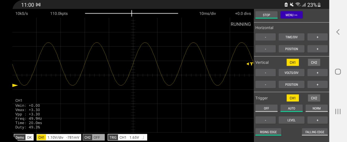
You can slide left and right and see the signal performance. On the right side, the horizontal and vertical adjustment options are available. The trigger option is also there for looking up the signal. You can select off, auto, and normal mode under the trigger function. From here time per division can be manually adjusted. Similarly, you can also adjust the volt per division functionality. To learn more about other functionality, you can manually verify all other functions.
The oscilloscope is a dual-channel oscilloscope where multiple signals can be read. Each of the channels can be turned On or Off and measurements parameters can be adjusted. For the demo signal, you can use both the channel1 and channel2 signals. But if you switch the mode to USB, you will only get 1 channel. To use the 2nd channel, you need to upgrade to the premium version. The app is so good that you can pay an extra amount to get another channel too. Anyway, we will only be using a single channel for testing our signal.
Hardware Assembly
Now the question is how to feed an external signal to a DIY Smartphone Oscilloscope? For this, we will use a very high-value resistor called 100K resistor and connect it across the GP26 Pin. This will protect the Pi Pico from over current. Similarly, we need a pair of 1K resistors. One resistor should be connected to the GND pin and another one to the 3.3V pin. Then join the other end of the resistor together. We are doing this because we need to measure both the negative and positive signals.

Here is a schematic for the application. We will feed the signal from the function generator to this GP26 pin via a 100K resistor. And the other Pin is the virtual ground pin. While supplying an input signal, both these pins are used.

We need this OTG device to connect the Pi Pico to Smartphone. This OTG is easily available in the market. Connect the USB OTG to your Smartphone and another end to the Raspberry Pi Pico Board. On your smartphone, you will see a pop-up window appearing. It will ask to allow scoppy to access the Pico. Click on OK.

Testing External Signals
We need a function generator here to test this DIY Smartphone Oscilloscope. But I don’t have a function generator. So I designed a signal generator using Arduino and a Rotary encoder. Using this function generator I can generate a square wave with variable frequency. You can also buy an 8$ XR2206 Function Generator Assembly kit.
You can follow our old post to design an Square Wave Generator or a Triangular Wave Generator.
Connect the output of the function generator to the Pi Pico Input. Use the virtual ground and also the Vin pin.
Now the frequency of 20Hz is set and fed to Pico. So a clear square wave is generated here. And when you compare the frequency it’s almost the same.

This is the 800Hz signal and pulse can be observed on the screen. The waveforms are still so clear.

You can feed various signals in KHz as well. Even the 1.2KHz frequency is fine.

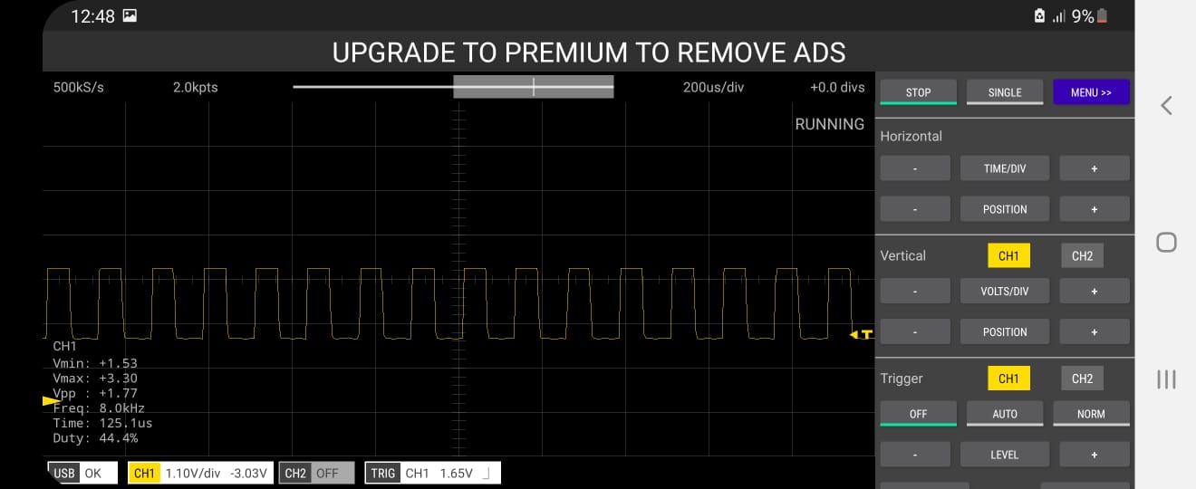
No distortion in the signal even up to the frequency of 8Khz.
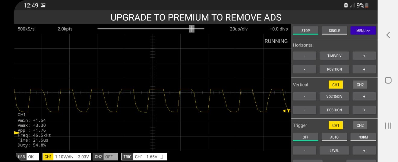
Now The frequency is increased very high now to 46KHz. Still, we are getting a square wave but there is slight switching of the signal.
You can measure the frequency up to 250KHz as this is the standard sampling frequency of Pi Pico. So design your own oscilloscope and observe the signal.
Measuring High Voltage Signals
The Pico can only read up to 3.3V. As we are using a voltage divider network here, the minimum range is -1.65V and the maximum range is +1.65V. So it can measure only voltage up to 3.3V input. What if we want to measure anything above 3.3V. For example, if you want to measure 100V peak-to-peak signal then how can we use this?
Since we have connected a 100K resistor across the signal pin, the device won’t get damaged by high voltage but it won’t measure it as some signals will be chopped.

For this you can use the standard circuit diagram if you want to read a high voltage signal which I won’t recommend. Here is a voltage divider network that will break the signal into 3 samples. If you are fed a 100V signal here you will get 100V, 10V & 1V signals respectively. You can use a rotary switch that is easily available in the market. And select the range as per your requirement.
Project PCB Gerber File & PCB Ordering Online
If you don’t want to assemble the circuit on a breadboard and you want PCB for the project, then here is the PCB for you. The PCB Board for Raspberry Pi Pico Oscilloscope is designed using EasyEDA online Circuit Schematics & PCB designing tool. The PCB looks something like below.

The Gerber File for the PCB is given below. You can simply download the Gerber File and order the PCB from ALLPCB at 1$ only.
You can use this Gerber file to order high quality PCB for this project. To do that visit the ALLPCB official website by clicking here: https://www.allpcb.com/.

You can now upload the Gerber File by choosing the Quote Now option. From these options, you can choose the Material Type, Dimensions, Quantity, Thickness, Solder Mask Color and other required parameters.

After filling all details, select your country and shipping method. Finally you can place the order.
You can assemble the components on the PCB Board.

This is how you can design your own DIY SmartPhone Oscilloscope using Raspberry Pi Pico & Scoppy at home for many of your projects.
Video: DIY SmartPhone Oscilloscope with Raspberry Pi Pico


9 Comments
How is the chematic with two channels?? Do both channels need own ground and +3,3V reference or can it be shared?
For 2nd channel use GP27 Pin. And yes the schematic would be same and shifted from GP26 to GP27.
Hi, very interesting project, I just buyed a pico for test it
Can you send a link about the rotary switch S1 ? I need to know the exact type for the pcb board.
Thanks
I am trying to visualize my output from an Arduino UNO which is 5v. How can I reduce it to 3.3v without a rotary switch?
I tried it now without anything and my scoppy is not registering anything other than noise.
»…wherever diodes in IO pins are referenced, it should parse as “ESD protection diodes”. These diodes are not rated for any continuous duty…«
→ The Pico RP2040 has no clamping diodes. Applying more than 0 … 3.3 V to GPIO is generally not a good idea.
My I know type of rotary switch, some link to eshop?
Hello , i want more détails about the last part,the parte of thé Rotary Switch and thé 900k and 90k and 9k resistances
Can I use a 104 ceramic capacitor across the ground and g26 pin to reduce the noise?
There are no specs for the rotary switch. Please send me them.
Thanks