


In this tutorial we will learn about Triangular Wave Generator Circuit with Op-Amp IC 741. The operational amplifier can be configured to generate the Triangular Wave Form.
Overview
Op-amp 741 IC is one of the most popular and versatile operation amplifiers and can be used in a lot of applications including, comparator, wave generator, amplifiers etc.
A triangular wave generator is an electronic circuit, which generates a triangular wave. An operational amplifier-based triangular waveform generator is a simple circuit that is widely used in function generators. The circuit for the Triangular wave generator is designed using 741 op amp.
Bill of Materials
Following are the components required for learning this tutorial practically.
| S.N. | Components | Description | Quantity |
|---|---|---|---|
| 1 | Resistor | 1 K Ω | 3 |
| 2 | Resistor | 10 K Ω | 1 |
| 3 | Resistor | 100 K Ω | 1 |
| 4 | Capacitor | 1 nF Ceramic Disk | 1 |
| 5 | Capacitor | 1 uF Ceramic Disk | 1 |
| 6 | LM741 | Op-Amp IC | 1 |
Op-Amp IC LM741
LM741 is an operational amplifier IC packed with many features. The IC is available in many different packages. The number of transistors used in the internal circuitry of the IC is 20. The IC can be used in a wide range of analog projects.
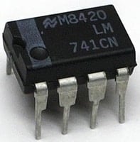
Its feature like high gain, low current consumption, and wide supply voltage makes it ideal to use in battery-operated circuits. Moreover, the IC is also overload protected from both sides i.e. input and output, this feature saves the internal circuitry of the IC from damage by overload.
Check the IC LM741 Datasheets
Triangular Wave Generator Circuit Diagram
This circuit is a simple example of a relaxation oscillator using a single op-amp as a comparator.

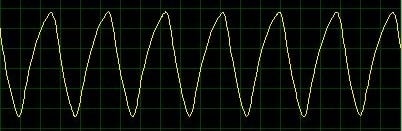
The circuit can be either assembled on a breadboard or simulated in Proteus. The waveform can be observed on Oscilloscope.
Working of the Op-Amp Based Triangular Wave Generator
First, let us assume that the capacitor is discharged. This makes the inverting input terminal at a voltage lower compared to the non-inverting input terminal. This is half the supply voltage from the resistor divider network.
The output will go high till the capacitor voltage goes above half the supply voltage. At this point, the voltage at the inverting input is greater than the non-inverting input. Afterward, the output will go low and discharge the capacitor. Simultaneously, the 10K resistor acts as hysteresis. When the output goes low, the voltage divider has a 1K and a 10K in parallel, which decreases the overall resistance and reduces the reference (Vref) voltage. The values of the hysteresis resistor which is 10K and the resistor divider network both can be changed to increase or decrease the frequency.
Now the output of the Op-Amp is AC coupled to produce a signal that has an equal positive and negative wave. This signal can easily be amplified.
Circuit Simulation
The circuit can be simulated using Proteus Software. The below-circuit simulated gives the perfect output on the Oscilloscope. You can change the value of resistors to observe the change in the waveform.

You can also check this post: Square Wave Generator Circuit with Op-Amp IC 741 and in order to view the waveform you can design your own DIY Oscilloscope at home.


