Close Menu
  • Articles
    • Learn Electronics
    • Product Review
    • Tech Articles
  • Electronics Circuits
    • 555 Timer Projects
    • Op-Amp Circuits
    • Power Electronics
  • Microcontrollers
    • Arduino Projects
    • STM32 Projects
    • AMB82-Mini IoT AI Camera
    • BLE Projects
  • IoT Projects
    • ESP8266 Projects
    • ESP32 Projects
    • ESP32 MicroPython
    • ESP32-CAM Projects
    • LoRa/LoRaWAN Projects
  • Raspberry Pi
    • Raspberry Pi Projects
    • Raspberry Pi Pico Projects
    • Raspberry Pi Pico W Projects
  • Electronics Calculator
Facebook X (Twitter) Instagram
  • About Us
  • Disclaimer
  • Privacy Policy
  • Contact Us
  • Advertise With Us
Facebook X (Twitter) Instagram Pinterest YouTube LinkedIn
How To Electronics
  • Articles
    • Learn Electronics
    • Product Review
    • Tech Articles
  • Electronics Circuits
    • 555 Timer Projects
    • Op-Amp Circuits
    • Power Electronics
  • Microcontrollers
    • Arduino Projects
    • STM32 Projects
    • AMB82-Mini IoT AI Camera
    • BLE Projects
  • IoT Projects
    • ESP8266 Projects
    • ESP32 Projects
    • ESP32 MicroPython
    • ESP32-CAM Projects
    • LoRa/LoRaWAN Projects
  • Raspberry Pi
    • Raspberry Pi Projects
    • Raspberry Pi Pico Projects
    • Raspberry Pi Pico W Projects
  • Electronics Calculator
How To Electronics
Home » Square Wave Generator Circuit with Op-Amp IC 741
Electronics Circuits Op-Amp Circuits

Square Wave Generator Circuit with Op-Amp IC 741

Mamtaz AlamBy Mamtaz AlamUpdated:August 21, 20222 Comments3 Mins Read
Share Facebook Twitter LinkedIn Telegram Reddit WhatsApp
Square Wave Generator Op Amp
Share
Facebook Twitter LinkedIn Pinterest Email Reddit Telegram WhatsApp

In this tutorial we will learn about Square Wave Generator Circuit with Op-Amp IC 741. The operational amplifier can be configured to generate the Triangular Wave Form.


Overview

Op-amp 741 IC is one of the most popular and versatile operation amplifiers and can be used in a lot of applications including, comparator, wave generator, amplifier, etc.

A square wave generator is an electronic circuit, which generates a square wave. The operational amplifier-based square waveform generator is a simple circuit that is widely used in function generators. The circuit for the Square wave generator is designed using 741 op amp.


Bill of Materials

Following are the components required for learning this tutorial practically.

S.N.Components DescriptionQuantity
1Resistor10 KΩ2
2Resistor12 KΩ1
3Capacitor1 µF, 16V (Electrolytic Capacitor)1
4Op-Amp ICLM741
1


Op-Amp IC LM741

LM741 is an operational amplifier IC packed with many features. The IC is available in many different packages. The number of transistors used in the internal circuitry of the IC is 20. The IC can be used in a wide range of analog projects.

LM741

Its feature like high gain, low current consumption, and wide supply voltage makes it ideal to use in battery-operated circuits. Moreover, the IC is also overload protected from both sides i.e. input and output, this feature saves the internal circuitry of the IC from damage by overload.

Check the IC LM741 Datasheets


Square Wave Generator Circuit Diagram

The circuit for square wave generator using Op-Amp is shown in the figure below. One capacitor is connected to the inverting terminal of an op-amp with one pin connected to the ground, and a resistor for charging and discharging the capacitor is also connected to the inverting terminal to output.

Square Wave Generator Circuit

One voltage divider is designed using two resistors & is connected to output and ground at the non-inverting pin.


Working of Square Wave Generator Using Op-Amp 741

Let us assume the voltage at inverting terminal be V2 which equals to the voltage across the capacitor. Also, let us assume the voltage at the non-inverting terminal be V1. The voltage difference between non-inverting and inverting terminal is referred to as differential input voltage and is given by Vin.

At the initial state when the capacitor is fully discharged, the voltage at inverting pin will be zero, i.e. V2 = 0V

Therefore, input differential voltage (Vin) = V1-V2 = V1-0 = V1

When Vin is positive the output is also positive, at this instance, the capacitor starts to charge through resistor R2 towards positive saturation voltage until V1 = V2.


When the voltage at the capacitor increases slightly more than the differential voltage V1.
Negative Vin = V1-V2 (V2>V1)

Then the output will be switched from positive saturation voltage to negative saturation voltage. In this instance, the capacitor starts to discharge through resistor R2 because V2 becomes greater than Vout. Again, after reaching V2 slightly less than V1 the output will again switch to positive saturation voltage. This process repeats again and again as a result square wave is generated.
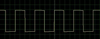

Circuit Simulation

The circuit can be simulated using Proteus Software. The below circuit simulation gives the perfect output on the Oscilloscope. You can change the value of resistors to observe the change in the waveform.

You can also check this post: Triangular Wave Generator Circuit with Op Amp IC 741 and in order to view the waveform you can design your own DIY Oscilloscope at home.

Share. Facebook Twitter Pinterest LinkedIn Tumblr Email Reddit Telegram WhatsApp
Previous ArticleIoT Decibelmeter with Sound Sensor & ESP8266
Next Article Dark Activated 220V Automatic Evening Lamp using LDR & IC 555

Related Posts

Water Level Alert using Float Sensor & 555 Timer

Water Level Alert using Float Sensor & 555 Timer

2K
Adjustable Auto On Off Delay Timer Circuit Using 555 IC

555 Based Adjustable Auto On Off Delay Timer Circuit

Updated:February 14, 20252K

12V DC to 220V AC Inverter Circuit & PCB

Updated:February 2, 20251461K
DIY Smart Blind Stick using Op-Amp & IR Sensor

DIY Smart Blind Stick using Op-Amp & IR Sensor

Updated:February 2, 202515K
Square Wave Generator Circuit with Op Amp IC LM358

Square Wave Generator Circuit with Op Amp IC LM358

Updated:February 2, 202513K
Gas Leak Detection & Alarm using 555 Timer IC

Gas Leak Detection & Alarm using 555 Timer IC

Updated:February 2, 202525K
View 2 Comments

2 Comments

  1. Andrew Androsow on December 22, 2021 11:24 PM

    Hello! It`s difficult to have two polar ( 5V/-5V for example) power supply in mobile devices. Is it any OP AMP generator for single power supply?

    Reply
  2. Alf on September 26, 2022 5:43 AM

    I built the abovr square wave cct, but doesnt work. I nhave double checked the layout, but still does not work

    Reply

CommentsCancel reply

Latest Posts
ESP32 Fingerprint Attendance System with Live Web Dashboard

ESP32 Fingerprint Attendance System with Live Web Dashboard

June 21, 2026
IoT Based PM & Air Quality Monitoring System using ESP32

IoT Based PM & Air Quality Monitoring System using ESP32

June 14, 2026
DIY ESP32 MLX90640 IR Thermal Camera with Live Web Display

DIY ESP32 MLX90640 IR Thermal Camera with Live Web Display

May 10, 2026
IoT Activity Tracker with ESP32 & Accelerometer Gyroscope

IoT Activity Tracker with ESP32 & Accelerometer/Gyroscope

May 2, 2026
A Guide to Sourcing Obsolete ICs for Vintage Projects

Beyond AliExpress: A Guide to Sourcing Obsolete ICs for Vintage Projects

April 21, 2026

ESP32 IoT Vehicle Motion Analyzer with MPU6050 & LIS3MDL

April 27, 2026
Building a Smart Sensor Node with a BLE Microcontroller

Building a Smart Sensor Node with a BLE Microcontroller

February 26, 2026
High-Accuracy Pitch, Roll, Yaw with ESP32 & BNO08x IMU

High-Accuracy Pitch, Roll, Yaw with ESP32 & BNO08x IMU

April 27, 2026
Top Posts & Pages
  • ESP32 Fingerprint Attendance System with Live Web Dashboard
    ESP32 Fingerprint Attendance System with Live Web Dashboard
  • IoT AC Energy Meter with PZEM-004T & ESP32 WebServer
    IoT AC Energy Meter with PZEM-004T & ESP32 WebServer
  • 12V DC to 220V AC Inverter Circuit & PCB
    12V DC to 220V AC Inverter Circuit & PCB
  • ESP32 CAN Bus Tutorial | Interfacing MCP2515 CAN Module with ESP32
    ESP32 CAN Bus Tutorial | Interfacing MCP2515 CAN Module with ESP32
  • How to use Modbus RTU with ESP32 to read Sensor Data
    How to use Modbus RTU with ESP32 to read Sensor Data
  • IoT Based ECG Monitoring with AD8232 ECG Sensor & ESP32
    IoT Based ECG Monitoring with AD8232 ECG Sensor & ESP32
  • Buck Converter: Basics, Working, Design & Application
    Buck Converter: Basics, Working, Design & Application
  • MAX30102 & Arduino: Heart Rate + Blood Oxygen Monitoring
    MAX30102 & Arduino: Heart Rate + Blood Oxygen Monitoring
Categories
  • Arduino Projects (197)
  • Articles (60)
    • Learn Electronics (19)
    • Product Review (15)
    • Tech Articles (28)
  • Electronics Circuits (46)
    • 555 Timer Projects (21)
    • Op-Amp Circuits (7)
    • Power Electronics (13)
  • IoT Projects (205)
    • ESP32 MicroPython (7)
    • ESP32 Projects (82)
    • ESP32-CAM Projects (15)
    • ESP8266 Projects (76)
    • LoRa/LoRaWAN Projects (22)
  • Microcontrollers (38)
    • AMB82-Mini IoT AI Camera (4)
    • BLE Projects (18)
    • STM32 Projects (19)
  • Raspberry Pi (93)
    • Raspberry Pi Pico Projects (57)
    • Raspberry Pi Pico W Projects (12)
    • Raspberry Pi Projects (24)
Follow Us
  • Facebook
  • Twitter
  • Pinterest
  • Instagram
  • YouTube
About Us

“‘How to Electronics’ is a vibrant community for electronics enthusiasts and professionals. We deliver latest insights in areas such as Embedded Systems, Power Electronics, AI, IoT, and Robotics. Our goal is to stimulate innovation and provide practical solutions for students, organizations, and industries. Join us to transform learning into a joyful journey of discovery and innovation.

Copyright © How To Electronics. All rights reserved.
  • About Us
  • Disclaimer
  • Privacy Policy
  • Contact Us
  • Advertise With Us

Type above and press Enter to search. Press Esc to cancel.

Ad Blocker Enabled!
Ad Blocker Enabled!
Looks like you're using an ad blocker. Please allow ads on our site. We rely on advertising to help fund our site.