

In this project we will make IoT Based Decibelmeter with Nodemcu ESP8266 & Sound Sensor & monitor online on Thingspeak Server.
Overview
A sound level meter is used for acoustic (sound that travels through the air) measurements. The best type of microphone for sound level meters is the condenser microphone, which combines precision with stability and reliability. The diaphragm of the microphone responds to changes in air pressure caused by sound waves. That is why the instrument is sometimes referred to as a Sound Pressure Level (SPL) Meter.
Decibelmeter are commonly used in noise pollution studies for the quantification of different kinds of noise, especially for industrial, environmental, mining and aircraft noise. The reading from a sound level meter does not correlate well to human-perceived loudness, which is better measured by a loudness meter. Specific loudness is a compressive nonlinearity and varies at certain levels and at certain frequencies. These metrics can also be calculated in a number of different ways.
In this IoT project, we will make Decibelmeter using ESP8266 & Sound Sensor. This DIY project is very simple and can be made at home for monitoring loudenss in dB. We will use Nodemcu ESP8266, Sound Module & Display either 16×2 LCD Display or OLED Display. The Sound Sensor will detect the sound and convert it into an analog voltage which is read by Nodemcu ESP8266. The Nodemcu connects to wifi and uploads the data to Thingspeak Server.
Before starting, you can check the previous post to get started with Sound Sensor:
1. Decibel Meter using Sound Module & Arduino with LCD Display
2. IoT Sound Level Monitor with ESP8266 & Sound Module
Bill of Materials
Following are the components required for making this project. All the components can be eaily purchased from Amazon. The components purchase link is given below.
| S.N. | Components Name | Quantity | Purchase Links |
|---|---|---|---|
| 1 | NodeMCU ESP8266 | 1 | Amazon | AliExpress |
| 2 | Sound Sensor | 1 | Amazon | AliExpress |
| 3 | OLED Display | 1 | Amazon | AliExpress |
| 4 | LCD Display | 1 | Amazon | AliExpress |
| 5 | Connecting Wires | 10 | Amazon | AliExpress |
| 6 | Breadboard | 1 | Amazon | AliExpress |
Microphone Sound Sensor
The microphone sound sensor, as the name says, detects sound. It gives a measurement of how loud a sound is. The sound sensor is a small board that combines a microphone (50Hz-10kHz) and some processing circuitry to convert sound waves into electrical signals. This electrical signal is fed to on-board LM393 High Precision Comparator to digitize it and is made available at OUT pin.

The module has a built-in potentiometer for sensitivity adjustment of the OUT signal. We can set a threshold by using a potentiometer. So that when the amplitude of the sound exceeds the threshold value, the module will output LOW otherwise HIGH.
Apart from this, the module has two LEDs. The Power LED will light up when the module is powered. The Status LED will light up when the digital output goes LOW.
The sound sensor only has three pins: VCC, GND & OUT. VCC pin supplies power for the sensor & works on 3.3V to 5V. OUT pin outputs HIGH when conditions are quiet and goes LOW when sound is detected.
Setting Up Thingspeak
In order to Monitor the Sensor Data on Thingspeak Server, you first need to Setup the Thingspeak. To set up the Thingspeak Server, visit https://thingspeak.com/. Create an account or simply sign in if you created the account earlier. Then create a new channel with following details.

After filling these details, save the channel. The go-to the API Key and copy the API key. This API key will be used in the program.
IoT Decibelmeter with ESP8266 & 16×2 I2C LCD Display
Let us first make Decibelmeter by interfacing Sound Sensor with Nodemcu ESP8266 & I6x2 I2C LCD Display. The connection diagram is given below.

Connect the Analog output pin of Sound Sensor to ESP8266. Similarly connect the I2C Pins (SDA, SCL) of LCD Display to D2 & D1 of ESP8266. Supply the LCD Display with 5V through Vin Pin. Similarly, supply the Sound Sensor with 3.3V supply through 3.3V Pin. You can also add 3 LED of a different color to Nodemcu D3, D4 & D5 Pins. This LED glows on the basis of different sound intensity.

Source Code: Decibelmeter with ESP8266 & LCD Display
Copy the complete code from below and upload it to the Nodemcu board. But before uploading make sure to change the wifi SSID, Password & Thingspeak API Key.
|
1 2 3 |
String apiKey = "14K8UL2QEK8BTHN6"; // Enter your Write API key from ThingSpeak const char *ssid = "Alexahome"; // replace with your wifi ssid and wpa2 key const char *pass = "12345678"; |
Check this complete source code below.
|
1 2 3 4 5 6 7 8 9 10 11 12 13 14 15 16 17 18 19 20 21 22 23 24 25 26 27 28 29 30 31 32 33 34 35 36 37 38 39 40 41 42 43 44 45 46 47 48 49 50 51 52 53 54 55 56 57 58 59 60 61 62 63 64 65 66 67 68 69 70 71 72 73 74 75 76 77 78 79 80 81 82 83 84 85 86 87 88 89 90 91 92 93 94 95 96 97 98 99 100 101 102 103 104 105 106 107 108 109 110 111 112 113 114 115 116 117 118 119 120 121 122 123 124 125 126 127 128 129 130 131 132 133 134 135 136 137 138 139 140 141 142 143 144 145 146 147 148 |
#include <ESP8266WiFi.h> #include <Wire.h> #include <LiquidCrystal_I2C.h> // Library for LCD LiquidCrystal_I2C lcd = LiquidCrystal_I2C(0x27, 16, 2); const int sampleWindow = 50; // Sample window width in mS (50 mS = 20Hz) unsigned int sample; #define SENSOR_PIN A0 #define PIN_QUIET D3 #define PIN_MODERATE D4 #define PIN_LOUD D5 String apiKey = "14K8UL2QEK8BTHN6"; // Enter your Write API key from ThingSpeak const char *ssid = "Alexahome"; // replace with your wifi ssid and wpa2 key const char *pass = "12345678"; const char* server = "api.thingspeak.com"; WiFiClient client; void setup () { pinMode (SENSOR_PIN, INPUT); // Set the signal pin as input pinMode(PIN_QUIET, OUTPUT); pinMode(PIN_MODERATE, OUTPUT); pinMode(PIN_LOUD, OUTPUT); digitalWrite(PIN_QUIET, LOW); digitalWrite(PIN_MODERATE, LOW); digitalWrite(PIN_LOUD, LOW); Serial.begin(115200); lcd.init(); // Turn on the backlight. lcd.backlight(); Serial.println("Connecting to "); Serial.println(ssid); lcd.setCursor(0, 0); lcd.print("Connecting to..."); lcd.setCursor(0, 1); lcd.print(ssid); WiFi.begin(ssid, pass); while (WiFi.status() != WL_CONNECTED) { delay(500); Serial.print("."); } Serial.println(""); Serial.println("WiFi connected"); lcd.clear(); lcd.setCursor(0, 0); lcd.print("Connected..."); delay(4000); lcd.clear(); } void loop () { unsigned long startMillis= millis(); // Start of sample window float peakToPeak = 0; // peak-to-peak level unsigned int signalMax = 0; //minimum value unsigned int signalMin = 1024; //maximum value // collect data for 50 mS while (millis() - startMillis < sampleWindow) { sample = analogRead(SENSOR_PIN); //get reading from microphone if (sample < 1024) // toss out spurious readings { if (sample > signalMax) { signalMax = sample; // save just the max levels } else if (sample < signalMin) { signalMin = sample; // save just the min levels } } } peakToPeak = signalMax - signalMin; // max - min = peak-peak amplitude int db = map(peakToPeak,20,900,49.5,90); //calibrate for deciBels lcd.setCursor(0, 0); lcd.print("Loudness: "); lcd.print(db); lcd.print("dB"); if (db <= 60) { lcd.setCursor(0, 1); lcd.print("Level: Quite"); digitalWrite(PIN_QUIET, HIGH); digitalWrite(PIN_MODERATE, LOW); digitalWrite(PIN_LOUD, LOW); } else if (db > 60 && db<85) { lcd.setCursor(0, 1); lcd.print("Level: Moderate"); digitalWrite(PIN_QUIET, LOW); digitalWrite(PIN_MODERATE, HIGH); digitalWrite(PIN_LOUD, LOW); } else if (db>=85) { lcd.setCursor(0, 1); lcd.print("Level: High"); digitalWrite(PIN_QUIET, LOW); digitalWrite(PIN_MODERATE, LOW); digitalWrite(PIN_LOUD, HIGH); } if (client.connect(server, 80)) // "184.106.153.149" or api.thingspeak.com { String postStr = apiKey; postStr += "&field1="; postStr += String(db); postStr += "r\n"; client.print("POST /update HTTP/1.1\n"); client.print("Host: api.thingspeak.com\n"); client.print("Connection: close\n"); client.print("X-THINGSPEAKAPIKEY: " + apiKey + "\n"); client.print("Content-Type: application/x-www-form-urlencoded\n"); client.print("Content-Length: "); client.print(postStr.length()); client.print("\n\n"); client.print(postStr); } client.stop(); delay(200); // thingspeak needs minimum 15 sec delay between updates. lcd.clear(); } |
Monitor Sound dB on LCD Display & Thingspeak
After the code is uploaded the Nodemcu will try connecting to wifi. All the process can be observed in LCD display. Now you can play music and observe the value on LCD Display.


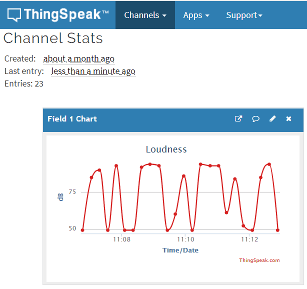
You can visit Thingspeak now to monitor the Decibelmeter dB data online. Just go to the private view of Thingspeak and you will see the following data logs & graphs.

IoT Decibelmeter with ESP8266 & OLED Display
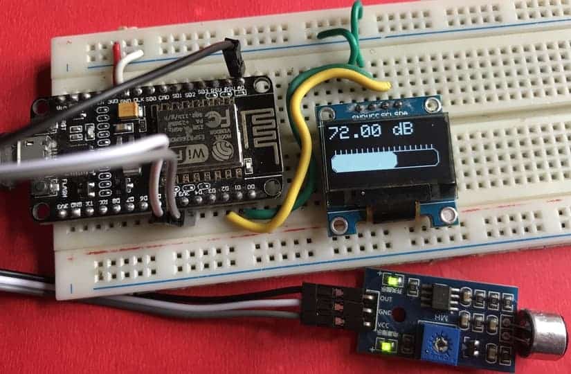
The Decibelmeter circuit diagram for Interfacing Sound Sensor with NodeMCU ESP8266 & OLED Display is given below. The connection is fairly simple.

The sound sensor and OLED display both need 3.3V power supply. So connect their VCC & GND terminal to 3.3V & GND of NodeMCU respectively. Connect the output pin of the sound sensor to the Nodemcu A0 pin. Connect the I2C pin, i.e SDA & SCL pin of OLED Display to Nodemcu D2 & D1 pin respectively.

Source Code: Decibelmeter with ESP8266 & OLED Display
Copy the complete code from below and upload it to the Nodemcu board. But before uploading make sure to change the wifi SSID, Password & Thingspeak API Key.
|
1 2 3 |
String apiKey = "14K8UL2QEK8BTHN6"; // Enter your Write API key from ThingSpeak const char *ssid = "Alexahome"; // replace with your wifi ssid and wpa2 key const char *pass = "12345678"; |
Check this complete source code below.
|
1 2 3 4 5 6 7 8 9 10 11 12 13 14 15 16 17 18 19 20 21 22 23 24 25 26 27 28 29 30 31 32 33 34 35 36 37 38 39 40 41 42 43 44 45 46 47 48 49 50 51 52 53 54 55 56 57 58 59 60 61 62 63 64 65 66 67 68 69 70 71 72 73 74 75 76 77 78 79 80 81 82 83 84 85 86 87 88 89 90 91 92 93 94 95 96 97 98 99 100 101 102 103 104 105 106 107 108 109 110 111 112 113 114 115 116 117 118 119 120 |
#include <ESP8266WiFi.h> #include <SPI.h> #include <Wire.h> #include <Adafruit_GFX.h> #include <Adafruit_SSD1306.h> #define SCREEN_WIDTH 128 // OLED display width, in pixels #define SCREEN_HEIGHT 64 // OLED display height, in pixels #define OLED_RESET -1 // Reset pin # (or -1 if sharing Arduino reset pin) Adafruit_SSD1306 display(SCREEN_WIDTH, SCREEN_HEIGHT, &Wire, OLED_RESET); String apiKey = "14K8UL2QEK8BTHN6"; // Enter your Write API key from ThingSpeak const char *ssid = "Alexahome"; // replace with your wifi ssid and wpa2 key const char *pass = "12345678"; const char* server = "api.thingspeak.com"; const int sampleWindow = 50; // Sample window width in mS (50 mS = 20Hz) unsigned int sample; WiFiClient client; void setup() { Serial.begin(115200); //Serial comms for debugging display.begin(SSD1306_SWITCHCAPVCC, 0x3C); //OLED display start display.display(); //show buffer display.clearDisplay(); //clear buffer display.setTextSize(1); //Set text size to 1 (1-6) display.setTextColor(WHITE); //Set text color to WHITE (no choice lol) display.setCursor(0,0); //cursor to upper left corner display.println("Decibelmeter"); //write title display.display(); //show title delay(2000); //wait 2 seconds WiFi.begin(ssid, pass); while (WiFi.status() != WL_CONNECTED) { delay(500); Serial.print("."); } Serial.println(""); Serial.println("WiFi connected"); display.clearDisplay(); display.setCursor(0,0); display.setTextSize(1); display.setTextColor(WHITE); display.print("WiFi connected"); display.display(); delay(4000); display.clearDisplay(); } //-------------------------------------------------------------------------------------------- // MAIN LOOP //-------------------------------------------------------------------------------------------- void loop() { unsigned long startMillis= millis(); // Start of sample window float peakToPeak = 0; // peak-to-peak level unsigned int signalMax = 0; //minimum value unsigned int signalMin = 1024; //maximum value // collect data for 50 mS while (millis() - startMillis < sampleWindow) { sample = analogRead(0); //get reading from microphone if (sample < 1024) // toss out spurious readings { if (sample > signalMax) { signalMax = sample; // save just the max levels } else if (sample < signalMin) { signalMin = sample; // save just the min levels } } } peakToPeak = signalMax - signalMin; // max - min = peak-peak amplitude float db = map(peakToPeak,20,900,49.5,90); //calibrate for deciBels display.setCursor(0,0); //cursor to upper left display.setTextSize(2); //set text size to 2 display.print(db); //write calibrated deciBels display.print(" dB"); //write units for(int x =5;x<114;x=x+6){ //draw scale display.drawLine(x, 32, x, 27, WHITE); } display.drawRoundRect(0, 32, 120, 20, 6, WHITE); //draw outline of bar graph int r = map(db,0,120,1,120); //set bar graph for width of screen display.fillRoundRect(1, 33, r, 18, 6, WHITE); //draw bar graph with a width of r display.display(); //show all that we just wrote & drew display.clearDisplay(); //clear the display if (client.connect(server, 80)) // "184.106.153.149" or api.thingspeak.com { String postStr = apiKey; postStr += "&field1="; postStr += String(db); postStr += "r\n"; client.print("POST /update HTTP/1.1\n"); client.print("Host: api.thingspeak.com\n"); client.print("Connection: close\n"); client.print("X-THINGSPEAKAPIKEY: " + apiKey + "\n"); client.print("Content-Type: application/x-www-form-urlencoded\n"); client.print("Content-Length: "); client.print(postStr.length()); client.print("\n\n"); client.print(postStr); } client.stop(); delay(150); } |
Monitor Sound dB on OLED Display & Thingspeak
After the code is uploaded the Nodemcu will try connecting to wifi. All the process can be observed in OLED display as shown below. Once the wifi is connected, the OLED display will start displaying the sound dB on OLED Screen.
You can again visit Thingspeak now to monitor the sound dB data online. Just go to the private view of Thingspeak and you will see the following data logs & graphs.
Video Tutorial & Guide


8 Comments
Hey Alex,
Great Project. I was looking for something like this for a long time.
The only thing confusing me is, that the “microphone” you use sends a signal if the sound pressure reaches a set value. If so, how can read min an max values if the signal you get is binary?
How should I change the time frame in ThingSpeak ?
Because mine it shows in days
The NodeMCU link to Amazon is no longer available. Can you recommend a suitable replacement? Would the directions work with any Arduino the same?
Hello! I didn’t understand two things:
– Why are you using an analogRead even if the output of LM393 is 0 or 1?
– The function map, why starts from 49.5?
Thanks
Gio
Why is no reference defined here? What “dB” is this? How is this referenced to the electric output of the microphone, and does it actually have a datasheet that maps sound pressure levels to output voltages at certain frequencies, and is this even repeatable across exemplars of this cheap thing?
I don’t see what you’re actually doing, where the numbers come from, but if you are just calculating dB_FS (full scale), this is a dangerous project that produces meaningless numbers that might get people their ears ruined (although one could make the point that whoever relies on this is crazy anyway, but still)
bro you cant use this sensor to measure loudness This kind of sensors only detect sound wave peaks (if can) and not enough sensitive to detect minor changes Dont mislead people
it isn’t a great project actually Totally wrong in both concept and practic
quien tiene un proyecyo similar que este funcionando correctamente?