
 with Data Logger")
Overview
In this project, we will build an highly accurate Decibel Meter using ESP32 WiFi Module and a special Sound Level Sensor Module. The decibel meter is capable of detecting the sound level between 35 dB to 115 dB. The Decibel Meter is highly accurate and doesn’t require any calibration as its already pre-calibrated.
We can interface the Sound Level Sensor with ESP32 using I2C protocol. The device can mesure detect the sound level and accurately monitor sound level in decibel (dB SPL). The detected sound level can be displayed on 0.96″ OLED Display. Apart from displaying the sound level on OLED, we can send the data to any IoT platform and use the data for graphical visualization and further analysis. In this example we sent the data to Ubidots platform.
You may take a look at a similar project that we build earlier using the Sound Level Sensor. These were not the accurate Decibelmeter but were designed for learning purpose only.
Bill of Materials
We need following components for this project. You can purchase the components from given links.
| S.N. | Components | Quantity | Purchase Link |
|---|---|---|---|
| 1 | ESP32 Board | 1 | Amazon | AliExpress | SunFounder |
| 2 | Sound Level (SPL) Sensor | 1 | PCB Artist |
| 3 | OLED Display | 1 | Amazon | AliExpress | SunFounder |
| 5 | Breadboard | 1 | Amazon | AliExpress | SunFounder |
| 6 | Connecting Wires | 1 | Amazon | AliExpress | SunFounder |
What is a Decibel Meter?
A decibel meter, also known as a sound pressure level (SPL) meter, is a device designed to measure sound pressure levels. The instrument uses a microphone to capture sound pressure changes and converts them into an electrical signal, which is then amplified. This amplified signal undergoes frequency and time weightings according to international standards, providing a standardized measurement in decibels (dB).

The decibel meter’s response to sound is comparable to that of the human ear, providing an objective measurement of noise levels in any given environment. The noise level readings, along with other potential acoustic parameters like the equivalent continuous sound level (Leq), are displayed on the device’s screen. You may use the Decibel Calculator to calculate the Decibel.
Decibel Sound Level Meter Module
The decibel meter module offered by PCB Artists is a compact, energy-efficient, and precise instrument for measuring sound pressure level in dB SPL. This Decibel Meter module can be easily interfaced with hardware like Arduino, ESP32, Raspberry Pi, or similar devices.

The I2C decibel meter module can be connected to any system with a 3.3V power output and I2C bus for communicating with the sound sensor module. It can detect the sound level from 35 dB to 115 dB with an accuracy of ±2 dB SPL. The sensor also doesn’t require any calibration as its factory calibrated.
Read about the PCB Artists Decibelmeter Here: I2C Decibel Meter Programming Manual
Features & Specifications
The PCB Artists decibel sound level meter module features
- High accuracy of ±2 dB SPL
- Measurement range of 35 dB to 115 dB
- Frequency Range of 30 Hz to 8 kHz
- Easy to use – standard I2C interface (I2C Address 0x48)
- Low power consumption, only 5mA @ 3.3V (measurement) and 100uA (sleep)
- Selectable response – A-weighted, C-weighted, Z-weighted
- Adjustable averaging time in the range of 10ms to 10,000 ms
125ms (fast mode) and 1,000ms (slow mode) supported - Threshold detection and interrupt
- 100-reading buffer to allow host MCU to sleep
- Stick to any surface using peel-off adhesive
- Low cost and small in size
Pinout
The sound level meter module has 5 pins. The INT (interrupt) pin is optional and may be left open if unused in your application.
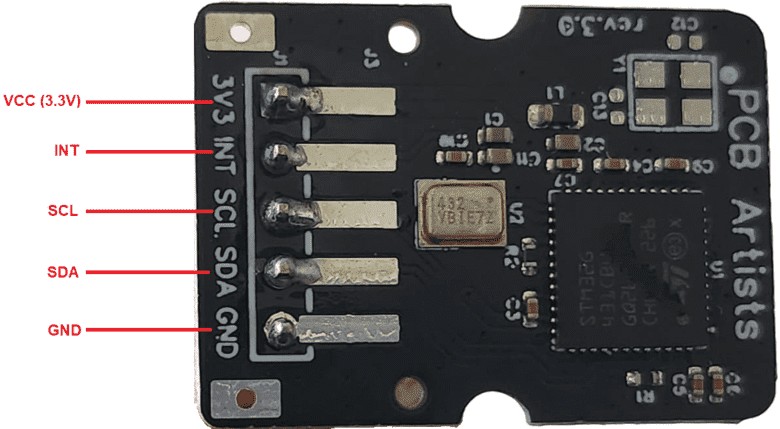
- 3V3 (Power supply input pin): Source clean 3.3V regulated power supply to this pin. The module typically consumes 5mA at 3.3V.
- INT(Open-drain interrupt pin, active low): The interrupt function is disabled by default. If enabled, the INT pin goes low when an interrupt is pending.
- SCL (Open-drain I2C SCL pin): Standard I2C bus SCL line, recommended pull-up is at least 10K.
- SDA (Open-drain I2C SDA pin): Standard I2C bus SDA line, recommended pull-up is at least 10K
- GND (Ground pin): Module ground, should be connected directly to the ground of the system power source or battery if possible.
Interfacing Decibel Meter Module with ESP32
Now let us interface the PCB Artists decibel sound level meter module with ESP32 WiFi/BLE Microcontroller. The connection is straight forward.

Connect the VCC, GND, SDA & SCL pin of Decibel Meter Module 3.3V, GND, GP21 & GP22 of ESP32 respectively. You may use a breadboard for assembly and jumper wires for connections.

Sample Code
Here is a sample code that can read sound level data sensed by Sound Level Decibel Meter Module using ESP32. The code initializes I2C communication protocol to read the value of sensor data. The sensor has an I2C Address of 0X48.
Copy the following code and upload it to the ESP32 Board. For uploading select the ESP32 Dev Module and the COM port.
|
1 2 3 4 5 6 7 8 9 10 11 12 13 14 15 16 17 18 19 20 21 22 23 24 25 26 27 28 29 30 31 32 33 34 35 36 37 38 39 40 41 42 43 44 45 46 47 48 49 50 51 52 53 54 55 56 57 58 59 60 61 62 63 64 |
#include <Wire.h> #define PCBARTISTS_DBM 0x48 #define I2C_REG_VERSION 0x00 #define I2C_REG_ID3 0x01 #define I2C_REG_ID2 0x02 #define I2C_REG_ID1 0x03 #define I2C_REG_ID0 0x04 #define I2C_REG_SCRATCH 0x05 #define I2C_REG_CONTROL 0x06 #define I2C_REG_TAVG_HIGH 0x07 #define I2C_REG_TAVG_LOW 0x08 #define I2C_REG_RESET 0x09 #define I2C_REG_DECIBEL 0x0A #define I2C_REG_MIN 0x0B #define I2C_REG_MAX 0x0C #define I2C_REG_THR_MIN 0x0D #define I2C_REG_THR_MAX 0x0E #define I2C_REG_HISTORY_0 0x14 #define I2C_REG_HISTORY_99 0x77 void setup() { Serial.begin(9600); Wire.begin(); byte version = reg_read(PCBARTISTS_DBM, I2C_REG_VERSION); Serial.print("dbMeter VERSION = 0x"); Serial.println(version, HEX); byte id[4]; id[0] = reg_read(PCBARTISTS_DBM, I2C_REG_ID3); id[1] = reg_read(PCBARTISTS_DBM, I2C_REG_ID2); id[2] = reg_read(PCBARTISTS_DBM, I2C_REG_ID1); id[3] = reg_read(PCBARTISTS_DBM, I2C_REG_ID0); Serial.print("Unique ID = "); Serial.print(id[0], HEX); Serial.print(" "); Serial.print(id[1], HEX); Serial.print(" "); Serial.print(id[2], HEX); Serial.print(" "); Serial.println(id[3], HEX); } void loop() { byte sound_level = reg_read(PCBARTISTS_DBM, I2C_REG_DECIBEL); Serial.print("Sound Level (dB SPL) = "); Serial.println(sound_level); delay(2000); } byte reg_read(byte addr, byte reg) { Wire.beginTransmission(addr); Wire.write(reg); Wire.endTransmission(); Wire.requestFrom(addr, (uint8_t)1); byte data = Wire.read(); return data; } |
After uploading the code, open the Serial Monitor. The Serial Monitor will show the Sound Level in dB (SPL).
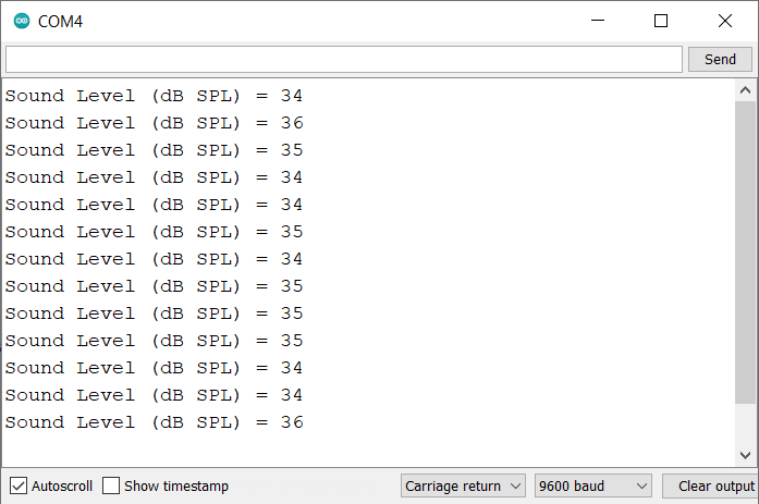
In a quite room the decibel meter value will be around 35. The decibel values increases on increasing the noise level. You may play music to detect the different level of sound. The is a highly accurate decibel meter as calibration is done at factory level.
Making ESP32 IoT Decibel Meter (SPL) with Data Logger
Now we have tested the Decibel Meter and read the values on Serail monitor, we can further enhance this project. We can use a 0.96″ I2C OLED Display for real-time reading of dB SPL value. We can also send the value to any IoT platform such as Blynk, Thingspeak, Ubidots or any other Server. This is what exctly we will do now. We will use Ubidots for data logging and real time remote analysis.
Circuit & Connections
Here is a simple connection for this part. We have added an extra Display for this project.

Connect the VCC, GND, SDA & SCL of SSD1306 0.96″ OLED Display to 3.3V, GND, GP21 & GP22 of ESP32 respectively.

Setting Up Ubidots Account
In order to monitor the data remotely, we need to send the Sound Sensor Decibel Meter value using ESP32 to Ubidots Account. So lets setup this account.
Create a Ubidots Account or log in using this link: https://stem.ubidots.com/.
Go to device and Click on Create.
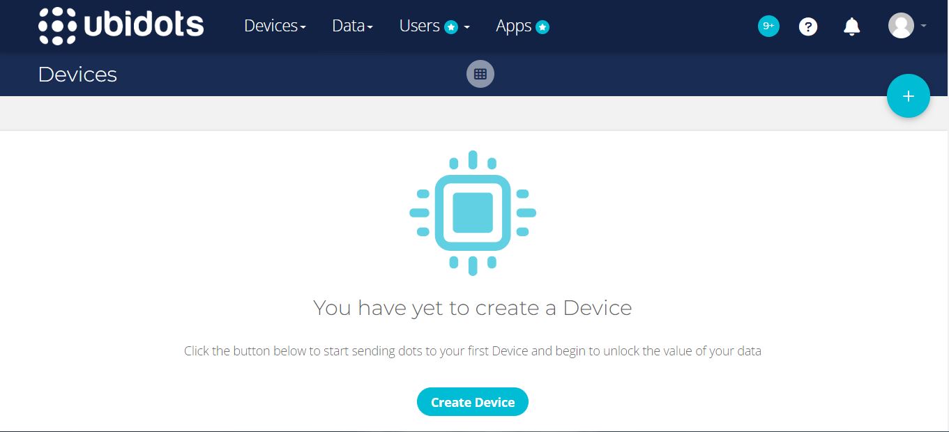
Choose a Blank Device and name the device as ESP32.
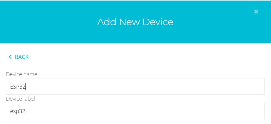
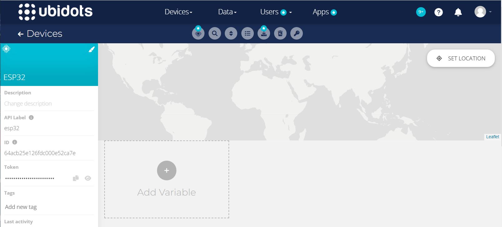
So a device name ESP32 will be created.
Now click on the created device. Here you need to create a variable.
Create a raw variable with name Decibel meter.
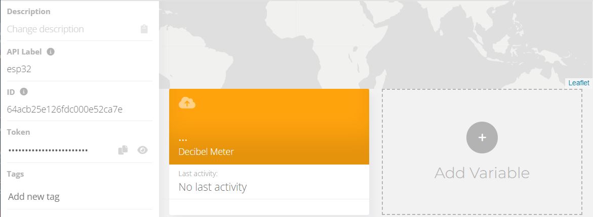
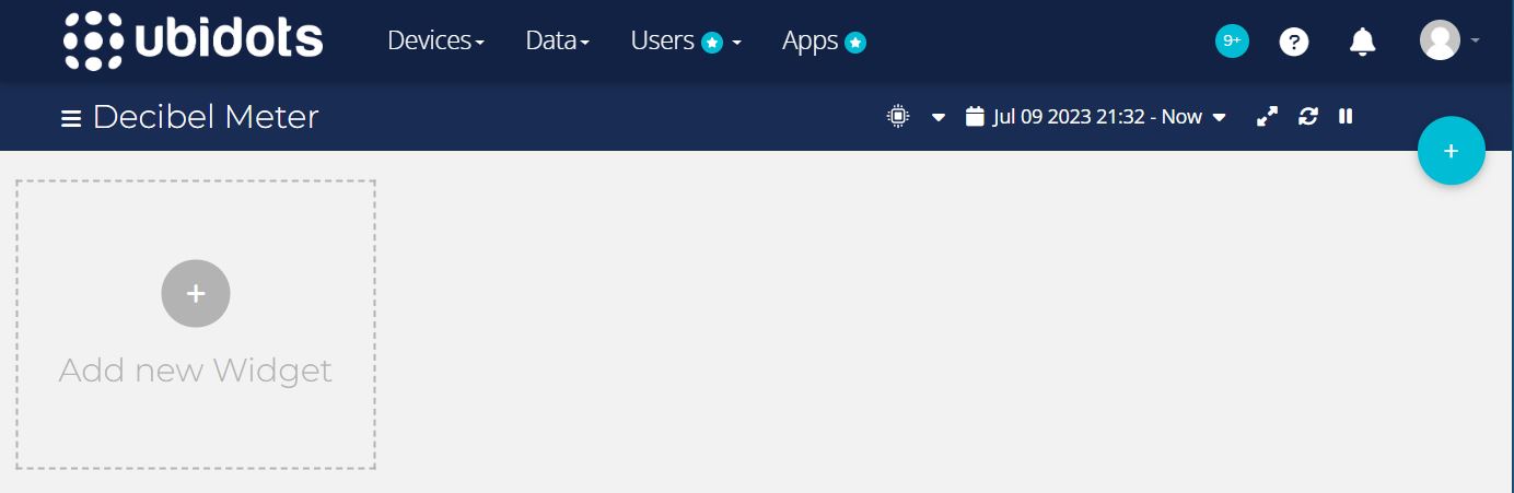
Now the device and the variable is created. So go back to dashboard. Here you need to setup the dashboard.
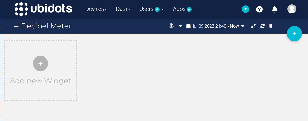
From the Add Widgets list, select two widgets as Gauge and Line Chart.
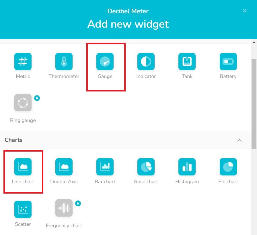
In both the Gauge and Line Chart Select the Decibel Meter variable from ESP32. Now the dashboard is ready which looks like this.
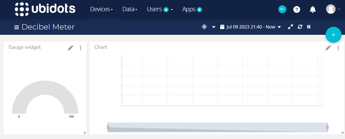
The gauge will display the real-time value of logged data. Similalrly the Bar graph will show the analysis of Decibel Meter data logged as per time.
Source Code/Program
Here is a complete code for the project now. The code will display the Sound Sensor dB SPL value on OLED Display. It will also send the data to Ubidots cloud.
From the following lines, change the WiFi SSID, Password and Ubidots Token.
|
1 2 3 |
#define WIFISSID "************" // Put your WifiSSID here #define PASSWORD "************" // Put your wifi password here #define TOKEN "************" // Put your Ubidots' TOKEN |
For the code compilation, you need to add pubsubclient library and Adafruit SSD1306 library.
After adding those libraries, you can upload the following code to ESP32 board.
|
1 2 3 4 5 6 7 8 9 10 11 12 13 14 15 16 17 18 19 20 21 22 23 24 25 26 27 28 29 30 31 32 33 34 35 36 37 38 39 40 41 42 43 44 45 46 47 48 49 50 51 52 53 54 55 56 57 58 59 60 61 62 63 64 65 66 67 68 69 70 71 72 73 74 75 76 77 78 79 80 81 82 83 84 85 86 87 88 89 90 91 92 93 94 95 96 97 98 99 100 101 102 103 104 105 106 107 108 109 110 111 112 113 114 115 116 117 118 119 120 121 122 123 124 125 126 127 128 129 130 131 132 133 134 135 136 137 138 139 140 141 142 143 144 145 146 147 148 149 150 151 152 153 154 155 156 157 158 159 160 161 162 163 164 165 166 167 168 169 170 171 172 173 174 175 176 177 178 179 180 181 182 183 184 185 186 187 |
#include <Wire.h> #include <WiFi.h> #include <PubSubClient.h> #include <Adafruit_SSD1306.h> #define SCREEN_WIDTH 128 // OLED display width, in pixels #define SCREEN_HEIGHT 64 // OLED display height, in pixels #define OLED_RESET -1 //Reset pin # (or -1 if sharing Arduino reset pin) #define SCREEN_ADDRESS 0x3C //See datasheet for Address Adafruit_SSD1306 display(SCREEN_WIDTH, SCREEN_HEIGHT, &Wire, OLED_RESET); #define PCBARTISTS_DBM 0x48 #define I2C_REG_VERSION 0x00 #define I2C_REG_ID3 0x01 #define I2C_REG_ID2 0x02 #define I2C_REG_ID1 0x03 #define I2C_REG_ID0 0x04 #define I2C_REG_SCRATCH 0x05 #define I2C_REG_CONTROL 0x06 #define I2C_REG_TAVG_HIGH 0x07 #define I2C_REG_TAVG_LOW 0x08 #define I2C_REG_RESET 0x09 #define I2C_REG_DECIBEL 0x0A #define I2C_REG_MIN 0x0B #define I2C_REG_MAX 0x0C #define I2C_REG_THR_MIN 0x0D #define I2C_REG_THR_MAX 0x0E #define I2C_REG_HISTORY_0 0x14 #define I2C_REG_HISTORY_99 0x77 #define WIFISSID "************" // Put your WifiSSID here #define PASSWORD "************" // Put your wifi password here #define TOKEN "************" // Put your Ubidots' TOKEN #define MQTT_CLIENT_NAME "ESP32" // MQTT client Name, please enter your own 8-12 alphanumeric character ASCII string; /**************************************** Define Constants ****************************************/ #define VARIABLE_LABEL1 "decibelmeter" // Assing the variable label #define DEVICE_LABEL "ESP32" char mqttBroker[] = "industrial.api.ubidots.com"; char payload[1000]; char topic1[150]; // Space to store values to send char str_decibelmeter[10]; /**************************************** Auxiliar Functions ****************************************/ WiFiClient ubidots; PubSubClient client(ubidots); void callback(char* topic, byte* payload, unsigned int length) { char p[length + 1]; memcpy(p, payload, length); p[length] = NULL; String message(p); Serial.write(payload, length); Serial.println(topic); } void reconnect() { // Loop until we're reconnected while (!client.connected()) { Serial.println("Attempting MQTT connection..."); // Attemp to connect if (client.connect(MQTT_CLIENT_NAME, TOKEN, "")) { Serial.println("Connected"); } else { Serial.print("Failed, rc="); Serial.print(client.state()); Serial.println(" try again in 2 seconds"); // Wait 2 seconds before retrying delay(2000); } } } /**************************************** Main Functions ****************************************/ void setup() { Serial.begin(115200); Wire.begin(); byte version = reg_read(PCBARTISTS_DBM, I2C_REG_VERSION); Serial.print("dbMeter VERSION = 0x"); Serial.println(version, HEX); byte id[4]; id[0] = reg_read(PCBARTISTS_DBM, I2C_REG_ID3); id[1] = reg_read(PCBARTISTS_DBM, I2C_REG_ID2); id[2] = reg_read(PCBARTISTS_DBM, I2C_REG_ID1); id[3] = reg_read(PCBARTISTS_DBM, I2C_REG_ID0); Serial.print("Unique ID = "); Serial.print(id[0], HEX); Serial.print(" "); Serial.print(id[1], HEX); Serial.print(" "); Serial.print(id[2], HEX); Serial.print(" "); Serial.println(id[3], HEX); // SSD1306_SWITCHCAPVCC = generate display voltage from 3.3V internally if (!display.begin(SSD1306_SWITCHCAPVCC, SCREEN_ADDRESS)) { Serial.println(F("SSD1306 allocation failed")); for (;;); // Don't proceed, loop forever } delay(500); display.clearDisplay(); WiFi.begin(WIFISSID, PASSWORD); Serial.println(); Serial.print("Waiting for WiFi Connection .............."); while (WiFi.status() != WL_CONNECTED) { Serial.print("."); delay(500); } Serial.println(""); Serial.println("WiFi Connected"); Serial.println("IP address: "); Serial.println(WiFi.localIP()); client.setServer(mqttBroker, 1883); client.setCallback(callback); } void loop() { if (!client.connected()) { reconnect(); } byte sound_level = reg_read(PCBARTISTS_DBM, I2C_REG_DECIBEL); Serial.print("Sound Level (dB SPL) = "); Serial.println(sound_level); display.clearDisplay(); display.setTextColor(SSD1306_WHITE); display.setCursor(20, 10); display.setTextSize(1); display.print("Decibelmeter: "); display.setCursor(30, 30); display.setTextSize(2); display.print(sound_level); display.print(" dB"); display.display(); dtostrf(sound_level, 4, 2, str_decibelmeter); sprintf(topic1, "%s%s", "/v1.6/devices/", DEVICE_LABEL); sprintf(payload, "%s", ""); sprintf(payload, "{\"%s\":", VARIABLE_LABEL1); sprintf(payload, "%s {\"value\": %s}}", payload, str_decibelmeter); Serial.println("Publishing temperature to Ubidots Cloud"); client.publish(topic1, payload); Serial.println(); client.loop(); delay(3000); } byte reg_read(byte addr, byte reg) { Wire.beginTransmission(addr); Wire.write(reg); Wire.endTransmission(); Wire.requestFrom(addr, (uint8_t)1); byte data = Wire.read(); return data; } |
Testing the Decibel Meter
Now the code is uploaded, we can start testing the Sound Sensor working ESP32. We can know how accurate is the Decibel meter.
The OLED will start displaying the value in dB SPL.
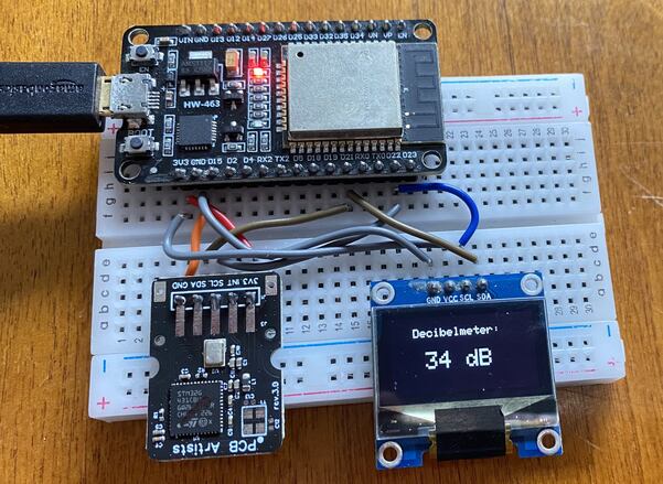
In a quite room, the sound level is almost 34-35 dB SPL.
You may play music and observe the rise in value of sound level as per music beat.
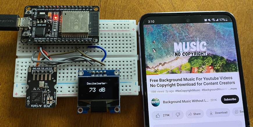
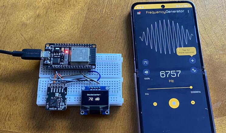
You can download the Frequency Generator app from Playstore, which can produce sound different sound with variable frequency.
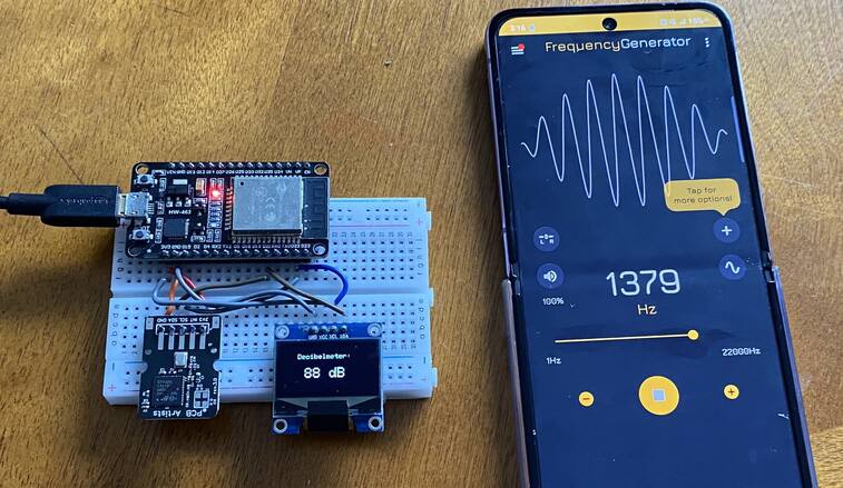
Change the frequency of sound and observe the reading on OLED.
The same data reading can also be observed remotely on Ubidots platform.
For that refresh the Ubidots dashboard and here you will observe the real-time value of Sound Level as well as graphical analysis of logged data.

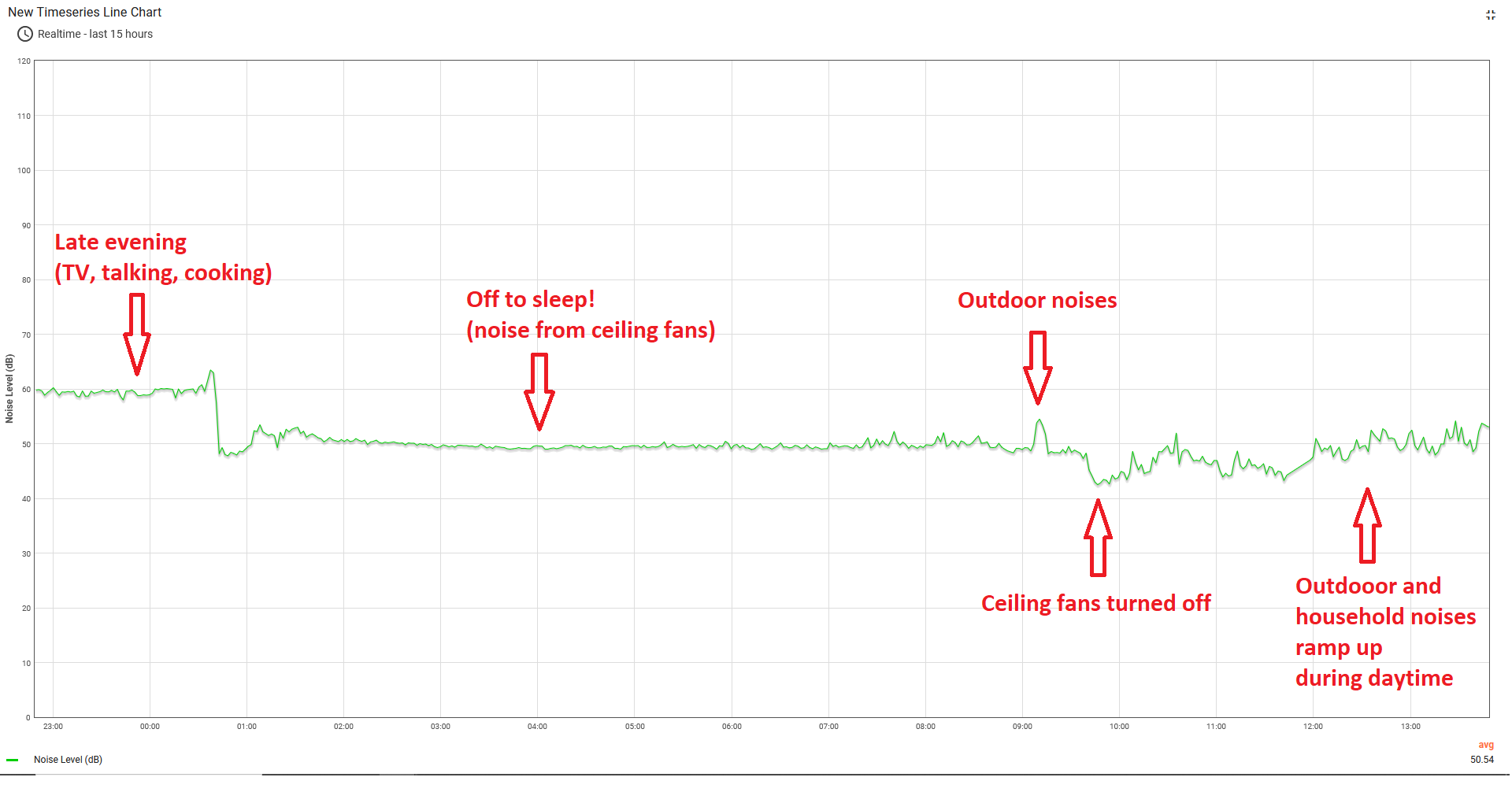
The graphical logged data can be used for further analysis.
Here is the analysis that we got from the observations. As the chart below demonstrates, the decibel values read from the ESP32 are highly repeatable and free from random spikes. It can hold a steady reading through durations of low noise and also responds very well to spikes or steps in audio levels.
Video Tutorial & Guide

Conclusion
In conclusion, the project successfully demonstrates the construction of a highly accurate Decibel Meter using an ESP32 WiFi Module and a Sound Level Sensor Module. This meter, which requires no further calibration owing to its pre-calibrated state, possesses the capacity to detect sound levels ranging between 35 dB to 115 dB.
Leveraging the I2C protocol, an effective interface was established between the ESP32 and the Sound Level Sensor, ensuring precise detection and monitoring of sound levels in decibel (dB SPL). The project not only facilitated the display of detected sound levels on a 0.96″ OLED Display but also utilized an IoT platform, Ubidots, for transmitting this data.


1 Comment
Hello, thanks for the tutorial…
I have a question, have you noticed a big difference in reliability with the noise sensor you use in this tutorial, compared to the LM393 that you used in the esp8266 tutorial?
The doubt arises because I was thinking of using it in a project, which hopefully one day would be commercial, and the LM393 sensor, in addition to being cheaper, is more widespread. The sensor you use here seems to be proprietary to a single grim reaper and to me, that’s a bit worrying.
What is your opinion about everything?
Thanks in advance!