


Overview
In this project, we will build a Soil Moisture Meter using Capacitive Soil Moisture Sensor V2.0 and Raspberry Pi Pico. We will display the measured Soil Moisture value on a 0.96″ I2C OLED Display.
This capacitive soil moisture sensor is different from most resistive sensors on the market, avoiding the problem that resistive sensors are easily corroded and greatly extending their working life. The Capacitive Soil moisture sensor can be inserted into the soil to measure the relative soil moisture content, which is commonly used in soil moisture monitoring, agricultural irrigation & forestry protection.
Components Required
In this guide, I used Elecrow Raspberry Pi Pico Starter Kit to test different Modules. You can buy the kit and perform some other operations as well. From this kit, you can use the following components.
1. Raspberry Pi Pico Board – 1
2. SSD1306 OLED Display – 1
3. Capacitive Soil Moisture Sensor V2.0 – 1
4. Breadboard – 1
5. Jumper Wires – 10
6. Micro-USB Cable – 1
Capacitive Soil Moisture Sensor V2.0

This capacitive soil moisture sensor V2.0 measures soil moisture levels by capacitive sensing rather than resistive sensing like other sensors on the market. It is made of corrosion-resistant material which gives it excellent service life. Insert it into the soil around your plants and impress your friends with real-time soil moisture data!

This module includes an onboard voltage regulator which gives it an operating voltage range of 3.3 ~ 5.5V. It is perfect for low-voltage MCUs, both 3.3V, and 5V. The Capacitive Soil Moisture Sensor can work with Raspberry Pi Pico via ADC.
The Capacitive Soil Moisture Sensor V2.0 works better and have improved result compared to its version of Capacitive Soil Moisture Sensor V1.2.
SSD1306 OLED Display
This is a 0.96-inch blue OLED display module. The display module can be interfaced with any microcontroller using SPI/IIC protocols. It is having a resolution of 128×64. The package includes a display board, a display, and 4 pin male header pre-soldered to the board.

OLED (Organic Light-Emitting Diode) is a self-light-emitting technology composed of a thin, multi-layered organic film placed between an anode and cathode. In contrast to LCD technology, OLED does not require a backlight. OLED possesses high application potential for virtually all types of displays and is regarded as the ultimate technology for the next generation of flat-panel displays.
A detailed tutorial on OLED Display & Raspberry Pi Pico interfacing is explained in the previous article. You can go through the article in detail to learn more about the OLED Display.
Interfacing Capacitive Soil Moisture Sensor & Raspberry Pi Pico
Now let us interface the Capacitive Soil Moisture Sensor with Raspberry Pi Pico & 0.96″ OLED Display. The connection diagram is very simple.

The SSD1306 OLED Display is an I2C Module. Therefore connect its SDA & SCL Pin to GP0 & GP1 of Raspberry Pi Pico. Power the OLED Display via 5V & GND pin of Raspberry Pi Pico.
The Capacitive Soil Moisture Sensor is an Analog Sensor. Connect its Analog output pin to GP26 of Raspberry Pi Pico. Power the Capacitive Soil Moisture Sensor via the 3.3V & GND pin of Raspberry Pi Pico.

MicroPython Code/Program
The code is divided into 2 parts. The 1st one is ssd1306.py and the other is main.py. The OLED Display doesn’t work directly as it requires SSD1306 Module library.
ssd1306.py
Copy the following code and save it as ssd1306.py in Raspberry Pi Pico.
|
1 2 3 4 5 6 7 8 9 10 11 12 13 14 15 16 17 18 19 20 21 22 23 24 25 26 27 28 29 30 31 32 33 34 35 36 37 38 39 40 41 42 43 44 45 46 47 48 49 50 51 52 53 54 55 56 57 58 59 60 61 62 63 64 65 66 67 68 69 70 71 72 73 74 75 76 77 78 79 80 81 82 83 84 85 86 87 88 89 90 91 92 93 94 95 96 97 98 99 100 101 102 103 104 105 106 107 108 109 110 111 112 113 114 115 116 117 118 119 120 121 122 123 124 125 126 127 128 129 130 131 132 133 134 135 136 137 138 139 140 141 142 143 144 145 146 147 148 149 150 151 152 153 154 155 |
# MicroPython SSD1306 OLED driver, I2C and SPI interfaces from micropython import const import framebuf # register definitions SET_CONTRAST = const(0x81) SET_ENTIRE_ON = const(0xA4) SET_NORM_INV = const(0xA6) SET_DISP = const(0xAE) SET_MEM_ADDR = const(0x20) SET_COL_ADDR = const(0x21) SET_PAGE_ADDR = const(0x22) SET_DISP_START_LINE = const(0x40) SET_SEG_REMAP = const(0xA0) SET_MUX_RATIO = const(0xA8) SET_COM_OUT_DIR = const(0xC0) SET_DISP_OFFSET = const(0xD3) SET_COM_PIN_CFG = const(0xDA) SET_DISP_CLK_DIV = const(0xD5) SET_PRECHARGE = const(0xD9) SET_VCOM_DESEL = const(0xDB) SET_CHARGE_PUMP = const(0x8D) # Subclassing FrameBuffer provides support for graphics primitives # http://docs.micropython.org/en/latest/pyboard/library/framebuf.html class SSD1306(framebuf.FrameBuffer): def __init__(self, width, height, external_vcc): self.width = width self.height = height self.external_vcc = external_vcc self.pages = self.height // 8 self.buffer = bytearray(self.pages * self.width) super().__init__(self.buffer, self.width, self.height, framebuf.MONO_VLSB) self.init_display() def init_display(self): for cmd in ( SET_DISP | 0x00, # off # address setting SET_MEM_ADDR, 0x00, # horizontal # resolution and layout SET_DISP_START_LINE | 0x00, SET_SEG_REMAP | 0x01, # column addr 127 mapped to SEG0 SET_MUX_RATIO, self.height - 1, SET_COM_OUT_DIR | 0x08, # scan from COM[N] to COM0 SET_DISP_OFFSET, 0x00, SET_COM_PIN_CFG, 0x02 if self.width > 2 * self.height else 0x12, # timing and driving scheme SET_DISP_CLK_DIV, 0x80, SET_PRECHARGE, 0x22 if self.external_vcc else 0xF1, SET_VCOM_DESEL, 0x30, # 0.83*Vcc # display SET_CONTRAST, 0xFF, # maximum SET_ENTIRE_ON, # output follows RAM contents SET_NORM_INV, # not inverted # charge pump SET_CHARGE_PUMP, 0x10 if self.external_vcc else 0x14, SET_DISP | 0x01, ): # on self.write_cmd(cmd) self.fill(0) self.show() def poweroff(self): self.write_cmd(SET_DISP | 0x00) def poweron(self): self.write_cmd(SET_DISP | 0x01) def contrast(self, contrast): self.write_cmd(SET_CONTRAST) self.write_cmd(contrast) def invert(self, invert): self.write_cmd(SET_NORM_INV | (invert & 1)) def show(self): x0 = 0 x1 = self.width - 1 if self.width == 64: # displays with width of 64 pixels are shifted by 32 x0 += 32 x1 += 32 self.write_cmd(SET_COL_ADDR) self.write_cmd(x0) self.write_cmd(x1) self.write_cmd(SET_PAGE_ADDR) self.write_cmd(0) self.write_cmd(self.pages - 1) self.write_data(self.buffer) class SSD1306_I2C(SSD1306): def __init__(self, width, height, i2c, addr=0x3C, external_vcc=False): self.i2c = i2c self.addr = addr self.temp = bytearray(2) self.write_list = [b"\x40", None] # Co=0, D/C#=1 super().__init__(width, height, external_vcc) def write_cmd(self, cmd): self.temp[0] = 0x80 # Co=1, D/C#=0 self.temp[1] = cmd self.i2c.writeto(self.addr, self.temp) def write_data(self, buf): self.write_list[1] = buf self.i2c.writevto(self.addr, self.write_list) class SSD1306_SPI(SSD1306): def __init__(self, width, height, spi, dc, res, cs, external_vcc=False): self.rate = 10 * 1024 * 1024 dc.init(dc.OUT, value=0) res.init(res.OUT, value=0) cs.init(cs.OUT, value=1) self.spi = spi self.dc = dc self.res = res self.cs = cs import time self.res(1) time.sleep_ms(1) self.res(0) time.sleep_ms(10) self.res(1) super().__init__(width, height, external_vcc) def write_cmd(self, cmd): self.spi.init(baudrate=self.rate, polarity=0, phase=0) self.cs(1) self.dc(0) self.cs(0) self.spi.write(bytearray([cmd])) self.cs(1) def write_data(self, buf): self.spi.init(baudrate=self.rate, polarity=0, phase=0) self.cs(1) self.dc(1) self.cs(0) self.spi.write(buf) self.cs(1) |
main.py
Copy the following code and save it as main.py in Raspberry Pi Pico.
|
1 2 3 4 5 6 7 8 9 10 11 12 13 14 15 16 17 18 19 20 21 22 23 24 25 26 27 28 29 30 31 32 33 34 35 36 |
# import required modules from machine import ADC, Pin, I2C from ssd1306 import SSD1306_I2C import utime # use variables instead of numbers: soil = ADC(Pin(26)) # Soil moisture PIN reference #Calibraton values min_moisture=19200 max_moisture=49300 readDelay = 0.5 # delay between readings WIDTH = 128 # oled display width HEIGHT = 64 # oled display height i2c = I2C(0, scl=Pin(1), sda=Pin(0), freq=200000) # Init I2C using pins GP0 & GP1 print("I2C Address : "+hex(i2c.scan()[0]).upper()) # Display device address print("I2C Configuration: "+str(i2c)) # Display I2C config oled = SSD1306_I2C(WIDTH, HEIGHT, i2c) # Init oled display while True: oled.fill(0) # read moisture value and convert to percentage into the calibration range moisture = (max_moisture-soil.read_u16())*100/(max_moisture-min_moisture) # print values print("moisture: " + "%.2f" % moisture +"% (adc: "+str(soil.read_u16())+")") oled.text("Soil Moisture",10,15) oled.text(str("%.2f" % moisture)+" %",35,35) oled.show() utime.sleep(readDelay) # set a delay between readings |
Testing & Calibration of Capacitive Soil Moisture Sensor
You can run this code now to check the working of the Capacitive Soil Moisture Sensor.

While talking about accuracy, the capacitive soil moisture sensor is not so much accurate as expected. But you can do the calibration to get the closest accurate reading. Just run the above code and check the sensor analog reading when the sensor is in dry air and when the sensor is in water. From here you can find the maximum and minimum analog values that can be mapped to percentage values from 0 to 100% as per the program.
|
1 2 3 |
#Calibraton values min_moisture=19200 max_moisture=49300 |
From above change the min_moisture and max_moisture with the value you got.
After filling in the values in the code, run the code again. Then dip the Soil Moisture Sensor in the soil. The OLED Display will show the moisture reading in percentage when put in different samples of soil.

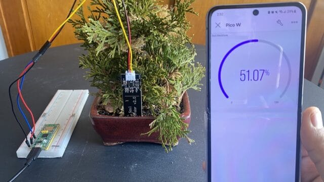
You can also check the IoT version of this project here: IoT Soil Meter


3 Comments
why does my sensor tell me different percentages and not just one percentage that was read? and how do I only get one percentage to calibrate the exact max and min moisture of my soil? it just jumps around. I would be grateful for your help 🙂
Because the micropython script reads the sensor every 0.5s. You would need to add extra script to record, for example, an average value for calibration, display purposes.
PLEASE HELP! THE SCRIPT IS NOT WORKING AND IT IS GIVING ME THIS ERROR:
Traceback (most recent call last):
File “”, line 19, in
IndexError: list index out of range