

Overview
The PiCar-X is an AI self-driving robot car that uses Raspberry Pi as its control center. The Robotic Kit is designed by SunFounder. The Kit comes with a Robot HAT for Raspberry Pi. The HAT integrates the motor driving, servo driving, and preset ADC, PWM, and digital pins to extend the functionality.
The PiCar-X’s has a 2-axis camera module, ultrasonic module, and line tracking modules that can provide the functions of color/face/traffic signs detection, automatic obstacle avoidance, automatic line tracking, etc. There is already a speaker in the Robot HAT to facilitate TTS (Text-to-Speech), sound effects, background music, etc. All of the PiCar-X functions, including GPIO control, computer vision, and deep learning, are implemented through the open-sourced Python programming language, OpenCV’s Computer Vision Library software, and Google’s TensorFlow for deep learning frameworks.
In this tutorial, we will go through the details of PiCar-X Robot Kit with Raspberry Pi. We will go through the Robot Assembly process & a method to use Raspbian OS with the System. We will install various dependencies and libraries for using all the sensors and modules with the Robot. We will then calibrate the motors and test some sensors part before implementing the full final applications. Later using the Robot and Python Code, we can make the following Robots:
- Obstacle Avoidance Robot
- Line Tracking Robot
- Text to Speech Robot
- Video Car Robot
- App Controlled AI Robot
Bill of Materials
We need the following components along with the SunFounder Robot Car Kit. You can purchase all these components from Amazon links:
| S.N. | Components | Quantity | Purchase Links |
|---|---|---|---|
| 1 | Raspberry Pi Ai Car Kit PiCar-X | 1 | Amazon | SunFounder |
| 2 | Raspberry Pi 4 | 1 | Amazon | SunFounder |
| 3 | Samsung 18650 Battery | 2 | AliExpress |
| 4 | SD Card 16/32 GB | 1 | Amazon | SunFounder |
| 5 | SD Card Adapter | 1 | Amazon | AliExpress |
| 6 | 18650 Battery Charger | 1 | Amazon | AliExpress |
Robot HAT cannot charge the battery, so you need to buy a battery charger at the same time.
Component List & Robot Assembly

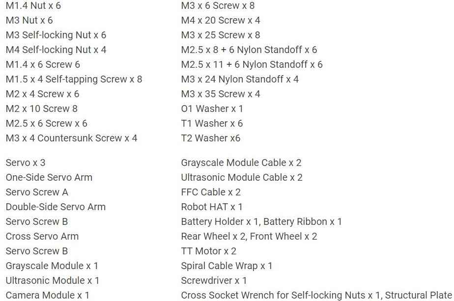
The Kit comes with all the necessary components required for the Robot which include the following components:
You need to buy a Raspberry Pi 4 Board and a pair of Samsung 18650 Batteries separately.

The most important part of this Kit is Robot HAT. With the Robot HAT board, the PiCar-X integrates left/right driving motors, servo motors for steering, and the camera’s pan/tilt functions, and pre-sets the Robot HAT’s ADC, PWM, and Digital I2C pins to allow for extensions to the standard functionality of the Raspberry Pi.

Both a speaker and a Bluetooth chip have been engineered into the Robot HAT for remote control of Text-to-Speech, sound effects, or even background music functionality.
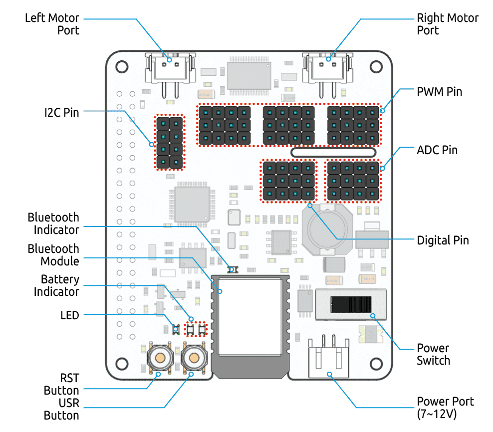
- RST Button: A short-press of the RST Button will cause any running programs to reset. A long press of the RST Button until the LED lights up, and then releasing will disconnect the Robot HAT’s Bluetooth chip.
- USR Button: The functions of the USR Button can be configured through programming. (Pressing down leads to an input of “0”, and releasing produces an input of “1” )
- LED: Configured through programming (Outputting ‘1’ turns the LED on, Outputting ‘0’ turns the LED off.)
- Battery Indicator: Battery voltage above 7.8V will light up the two indicator LEDs. Battery voltage ranging from 6.7V to 7.8V will only light up one LED, voltage below 6.7V will turn both LEDs off.
- Bluetooth Indicator: The Bluetooth indicator LED will stay on with a solid Bluetooth connection, and blink rapidly during signal transmission. The LED will blink at 1-second intervals if the Bluetooth is disconnected.
- Left Motor Port & Right Motor Port: These ports are used to connect the left and right motors.
- Power Port: A power port accepts an input voltage of 7-12V. A pair of Lithium-Ion batteries is a good choice to power the entire board.
- Power Switch: This switch is used to turn on/off the entire Raspberry Pi System.
To assemble the components together and make a perfect Robotic Car you can follow the Assembly Guide. The PDF Document has all the images and a pictorial view for easy help with assembly.

Servo Motor & Sensor Connections

The Picar-X Raspberry Pi Robot has 3 servo motors Pan, Tilt & Steering Servo. It also has 2 sensors; Ultrasonic Sensor HC-SR04 and Grayscale Sensor Module.
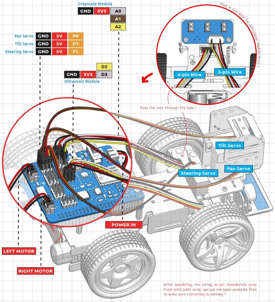
The Pan, Tilt, and Steering Servo are connected to the following Pins of Robot HAT.
| Servo 1 (Pan) | RPI HAT | Servo 2 (Tilt) | RPI HAT | Servo 3 (Steer) | RPI HAT |
|---|---|---|---|---|---|
| VCC | 5V | VCC | 5V | VCC | 5V |
| GND | GND | GND | GND | GND | GND |
| Signal | P0 | Signal | P1 | Signal | P2 |
The Ultrasonic Sensor HC-SR04 is connected to the following pins of Robot HAT.
| Ultrasonic Sensor | RPI HAT |
|---|---|
| VCC | 3.3V |
| GND | GND |
| TRIG | D2 |
| ECHO | D3 |
The Grayscale Module is connected to the following pins of Robot HAT.
| Grayscale Sensor | RPI HAT |
|---|---|
| VCC | 3.3V |
| GND | GND |
| Output1 | A0 |
| Output2 | A1 |
| Output3 | A2 |
After Robot assembly, you may start the Raspberry Pi OS & program Setup part.
Note: If the servos have been powered on through the Robot HAT after assembly, do not manually force the steering gear, as this could cause damage to the servo.
Raspberry Pi OS Installation & Setup
The Raspberry Pi is a low-cost, computer that plugs into a computer monitor or TV, and uses a standard keyboard and mouse. It is also used as a tool to learn Python programming.
Before moving to the Robotic project part, we need to set up the Raspberry Pi Board. For this, you need a 16/32 GB SD Card. We need to install OS to the system stored in SD Card.
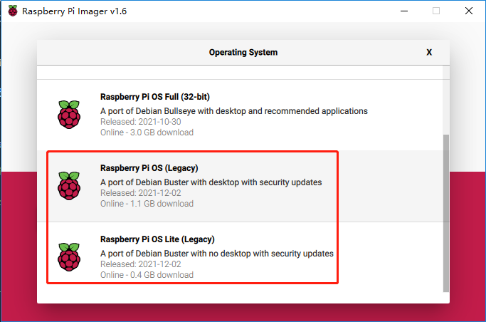
The OS installation part and setup part can be followed on Raspberry Pi OS Setup. But for this robotic project part, it is recommended to install Raspberry Pi OS(Legacy), this will allow you to go to the Raspberry Pi desktop to view the footage taken by the camera.
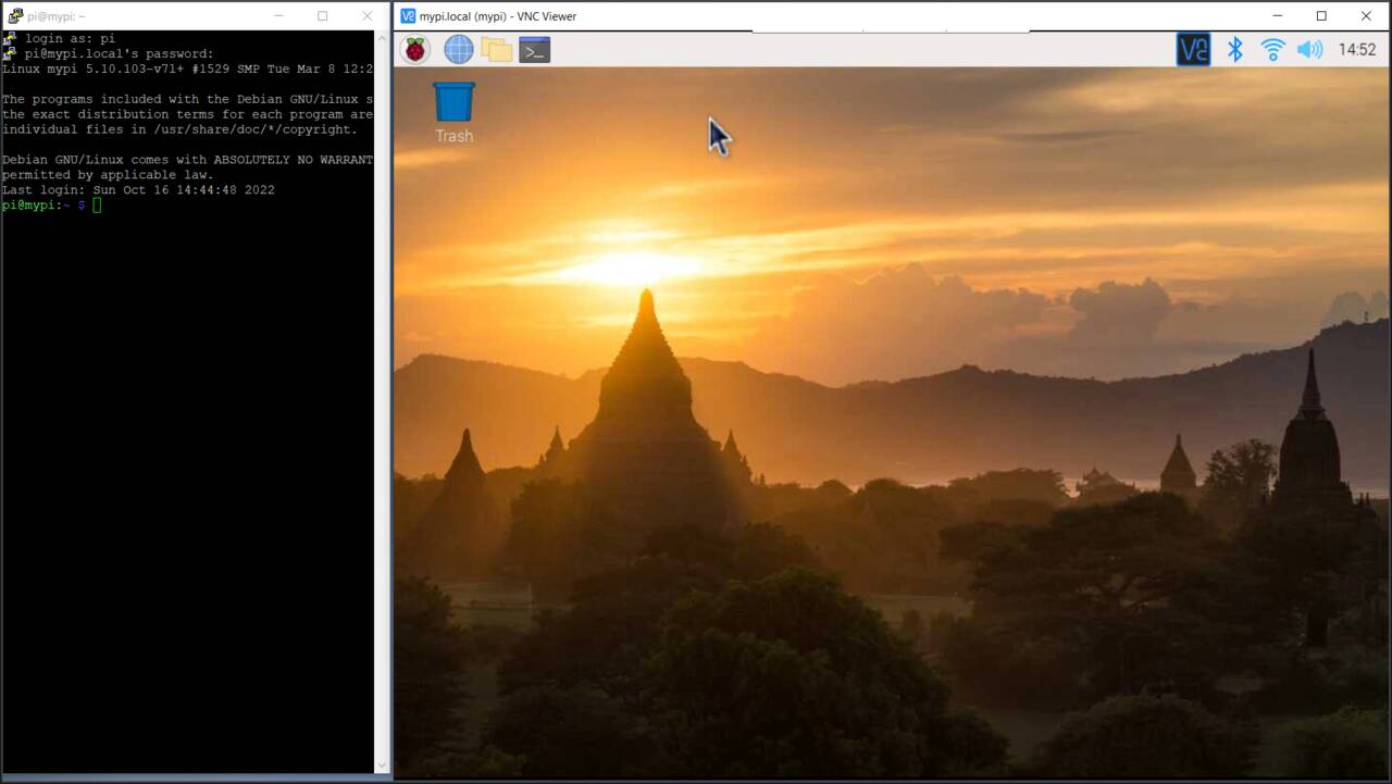
You can either use the HDMI Screen or enable SSH and connect the Raspberry Pi to VNC Viewer using the local IP Address, username, and password.
In my case, I am using the Putty Software to connect to my Raspberry Pi remotely. I am also using the VNC Viewer to set up the Python programming with Thonny.
Now we need to install many modules and dependencies to the system.
Installing Python Modules & Libraries
The Picar-X Robot should be turned ON and Raspberry Pi should be connected to the network. Now let’s install all the Python Modules and libraries.
Lets first update the system using following commands.
|
1 2 |
sudo apt update sudo apt upgrade |
Then install the Python3 related packages.
|
1 |
sudo apt install git python3-pip python3-setuptools python3-smbus |
Download & install the libraries for Robot-Hat.
|
1 2 3 4 |
cd /home/pi/ git clone https://github.com/sunfounder/robot-hat.git cd robot-hat sudo python3 setup.py install |
Running ‘setup.py‘ will download some necessary components. Your download may have failed due to network issues. You may need to download it again at this point. See the following interface, type ‘Y‘, and press Enter.
Now, download and install the ‘vilib‘ module.
|
1 2 3 4 |
cd /home/pi/ git clone https://github.com/sunfounder/vilib.git cd vilib sudo python3 install.py |
Similarly download and install the ‘picar-x‘ module.
|
1 2 3 4 |
cd /home/pi/ git clone -b v2.0 https://github.com/sunfounder/picar-x.git cd picar-x sudo python3 setup.py install |
This will download a large number of files, therefore it will take time.

Once the download is complete, run the ‘i2samp.sh‘ script to install the components required by the i2s amplifier, otherwise the picar-x will have no sound.
|
1 2 |
cd /home/pi/picar-x sudo bash i2samp.sh |
Type ‘y‘ and press enter to continue running the script.

Type ‘y‘ and press enter to run ‘/dev/zero‘ in the background.

Type y and press enter to restart the Picar-X.

After restarting, the Raspberry Pi will connect to the Network and will play a sound.
If there is no sound after restarting, you may need to run the ‘i2samp.sh‘ script several times.
All the installation and setup part is complete here.
Adjusting Servo Angles

The angle range of the servo is -90~90, but the angle set at the factory is random, maybe 0°, maybe 45°. If we assemble it with such an angle directly, it will lead to a chaotic state after the robot runs the code, or worse, it will cause the servo to block and burn out.
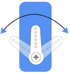
So here we need to set all the servo angles to 0° and then install them so that the servo angle is in the middle, no matter which direction to turn.
to do that run ‘servo_zeroing.py‘ in the ‘example/‘ folder.
|
1 2 |
cd /home/pi/picar-x/example sudo python3 servo_zeroing.py |
If you get an error, try re-enabling the Raspberry Pi’s I2C port.
Next, plug the servo cable into the P11 port as follows. Since there are 3 servo motors do the same for all three servos as all of the requires position adjustments.
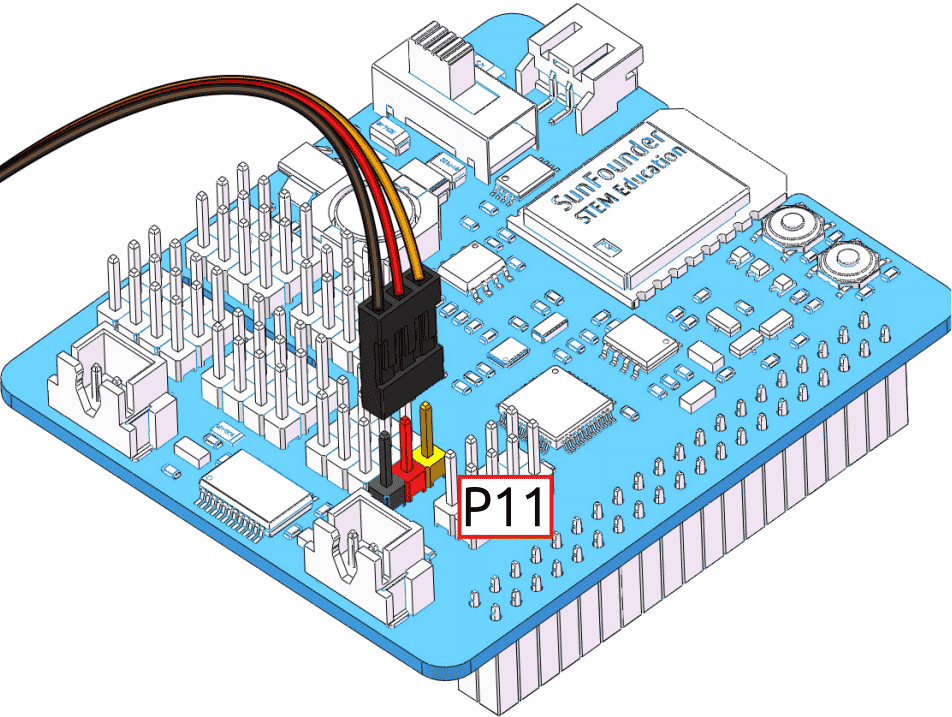
At this point, you will see the servo arm rotate to a specific position (0°). If the servo arm does not return to 0°, press the RST button to restart the Robot HAT.
Note:
- Do not unplug this servo cable before fixing it with the servo screw, you can unplug it after fixing it.
- Do not rotate the servo while it is powered on to avoid damage; if the servo shaft is not inserted at the right angle, pull the servo out and reinsert it.
- Before assembling each servo, you need to plug the servo cable into P11 and turn on the power to set its angle to 0°.
For more details follow the SunFounder Servo Adjustment guide.
Calibrating the PiCar-X Raspberry Pi Robot
The final stage of the Robot setup is the calibration part. Some servo angles may be slightly tilted due to possible deviations during Robot Assembly or limitations of the servos. Therefore we need to calibrate them.
Run the ‘calibration.py‘ from using the following command.
|
1 2 |
cd /home/pi/picar-x/example/calibration sudo python3 calibration.py |
After running the code, you will see the following interface displayed in the terminal.
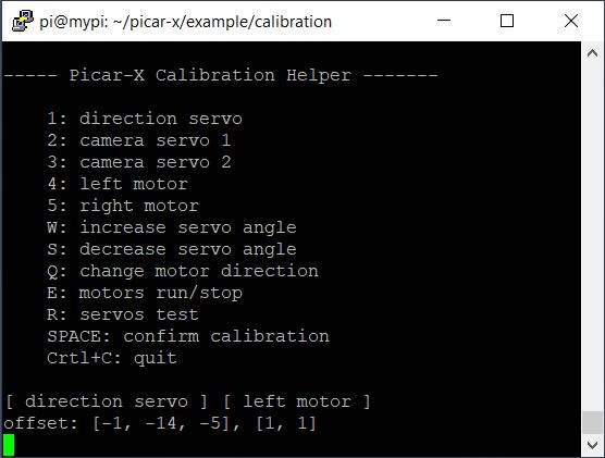
- The
Rkey is used to test whether the servo that controls the direction of the front wheel can work normally and is not damaged. - Press the number key
1to select the front wheel servo, and then press theW/Skey to let the front wheel looks as forward as possible without skewing left and right. - Press the number key
2to select the Pan servo, then press theW/Skey to make the pan/tilt platform look straight ahead and not tilt left or right. - Press the number key
3to select the tilt servo, then press theW/Skey to make the pan/tilt platform look straight ahead and not tilt up and down. - Since the wiring of the motors may be reversed during installation, you can press
Eto test whether the car can move forward normally. If not, use the number keys4and5to select the left and right motors, then press theQkey to calibrate the rotation direction. - When the calibration is completed, press the
Spacebarto save the calibration parameters. There will be a prompt to enteryto confirm, and then pressescto exit the program to complete the calibration.
Testing the PiCar-X Raspberry Pi Robot
Since the calibration part is complete, you can start testing the Robot by moving it. The first project is to test the basic movement of Picar-X.
To test the Robot, run the following command.
|
1 2 |
cd /home/pi/picar-x/example sudo python3 move.py |
After running the code, PiCar-X will move forward, turn in an S-shape, stop and shake its head.

Python Code
Open the Thonny IDE and load the file ‘move.py‘ from the path path like picar-x/example.
Now you can Modify/Reset/Copy/Run/Stop the code below.
|
1 2 3 4 5 6 7 8 9 10 11 12 13 14 15 16 17 18 19 20 21 22 23 24 25 26 27 28 29 30 31 32 33 34 35 36 37 38 39 40 41 42 |
from picarx import Picarx import time if __name__ == "__main__": try: px = Picarx() px.forward(30) time.sleep(0.5) for angle in range(0,35): px.set_dir_servo_angle(angle) time.sleep(0.01) for angle in range(35,-35,-1): px.set_dir_servo_angle(angle) time.sleep(0.01) for angle in range(-35,0): px.set_dir_servo_angle(angle) time.sleep(0.01) px.forward(0) time.sleep(1) for angle in range(0,35): px.set_camera_servo1_angle(angle) time.sleep(0.01) for angle in range(35,-35,-1): px.set_camera_servo1_angle(angle) time.sleep(0.01) for angle in range(-35,0): px.set_camera_servo1_angle(angle) time.sleep(0.01) for angle in range(0,35): px.set_camera_servo2_angle(angle) time.sleep(0.01) for angle in range(35,-35,-1): px.set_camera_servo2_angle(angle) time.sleep(0.01) for angle in range(-35,0): px.set_camera_servo2_angle(angle) time.sleep(0.01) finally: px.forward(0) |
Code Explanation & Working
The code can be used to control steering gear and wheels and will make the PiCar-X move forward, turn in an S-shape, or shake its head.
First we need to import Picarx from picarx library and time.
|
1 2 |
from picarx import Picarx import time |
The following function with the for loop is then used to make PiCar-X move forward, change directions, and move the camera’s pan/tilt.
|
1 2 3 4 |
px.forward(speed) px.set_dir_servo_angle(angle) px.set_camera_servo1_angle(angle) px.set_camera_servo2_angle(angle) |
forward(): Orders the PiCar-X go forward at a givenspeed.set_dir_servo_angle: Turns the Steering servo to a specificangle.set_camera_servo1_angle: Turns the Pan servo to a specificangle.set_camera_servo2_angle: Turns the Tilt servo to a specificangle.
This is how you can set up and test the PiCar-X Self-Driving AI Robot with Raspberry Pi 4. Apart from this testing part you can make more than 15 projects using Python Code and Blockly.
Video Tutorial & Guide


