

Overview:
In this project, we’ll set up an Automatic Plant Watering System using Arduino and a Soil Moisture Sensor. Keeping plants watered just right can be a challenge. Sometimes we forget, or we might water them too much. Our solution helps ensure plants always get the right amount of water.
Our system uses the Capacitive Soil Moisture Sensor to see if the soil needs water. When it’s too dry (below 40% moisture), the Arduino tells a relay to turn on a motor, which pumps water to the plant. The cool part? You can see the soil’s moisture level on an OLED Display. This display also shows if the motor is on or off. When the soil is moist enough, the motor stops.
In this article, we’ll walk you through setting up the system. By the end, you’ll understand how the Soil Moisture Sensor and OLED Display work together with the Arduino and how the motor waters your plants when needed. You may check IoT Plant Watering System Project made using ESP8266
Bill of Materials:
The following are the components required for making Automatic Plant Watering System project.
| S.N. | Components | Quantity | Purchase Link |
|---|---|---|---|
| 1 | Arduino Nano | 1 | Amazon | AliExpress | SunFounder |
| 2 | Capacitive Soil Moisture Sensor | 1 | Amazon | AliExpress | SunFounder |
| 3 | Relay 5V | 1 | Amazon | AliExpress | SunFounder |
| 4 | Transistor 2N2222 | 1 | Amazon | AliExpress | SunFounder |
| 5 | Resistor 1K | 2 | Amazon | AliExpress | SunFounder |
| 6 | LED Red | 1 | Amazon | AliExpress | SunFounder |
| 7 | Diode 1N4007 | 1 | Amazon | AliExpress | SunFounder |
| 8 | 0.96" I2C OLED Display | 1 | Amazon | AliExpress | SunFounder |
| 9 | Water Pump Motor | 1 | Amazon | AliExpress |
| 10 | Male/Female Headers | 2 | Amazon | AliExpress | SunFounder |
| 11 | Capacitor 47uF, 25V | 1 | Amazon | AliExpress | SunFounder |
| 12 | DC Jack | 1 | Amazon | AliExpress |
| 13 | 9V DC Adapter | 1 | Amazon | AliExpress | SunFounder |
| 14 | Jumper Wires | 10 | Amazon | AliExpress | SunFounder |
Capacitive Soil Moisture Sensor
This is an analog capacitive soil moisture sensor which measures soil moisture levels by capacitive sensing. This means the capacitance is varied on the basis of water content present in the soil. You can convert the capacitance into voltage level basically from 1.2V minimum to 3.0V maximum. The advantage of Capacitive Soil Moisture Sensor is that they are made of a corrosion-resistant material giving it a long service life.

Features & Specifications
- Supports 3-Pin Sensor interface
- Analog output
- Operating Voltage: DC 3.3-5.5V
- Output Voltage: DC 0-3.0V
- Interface: PH2.0-3P
- Size: 99x16mm/3.9×0.63″
To learn more about Capacitive Soil Moisture Sensor you can follow this post: Capacitive Soil Moisture Sensor Basic Interfacing Guide
DC 3-6V Micro Submersible Mini Water Pump
The DC 3-6 V Mini Micro Submersible Water Pump is a low cost, small size Submersible Pump Motor. It operates from a 2.5 ~ 6V power supply. It can take up to 120 liters per hour with a very low current consumption of 220mA. Just connect the tube pipe to the motor outlet, submerge it in water, and power it.

Features & Specifications
- Operating Voltage: 2.5 ~ 6V
- Operating Current: 130 ~ 220mA
- Flow Rate: 80 ~ 120 L/H
- Maximum Lift: 40 ~ 110 mm
- Outlet Outside Diameter: 7.5 mm
- Outlet Inside Diameter: 5 mm
0.96″ I2C OLED Display
The 0.96″ I2C OLED display is a compact and versatile screen popular among electronics enthusiasts. Its OLED (Organic Light-Emitting Diode) nature means it produces its own light, achieving a high contrast ratio by turning off individual pixels for pure black. Unlike LCDs, this results in vibrant displays, even on such a small scale.

Using the I2C (Inter-Integrated Circuit) communication protocol, the display connects via only two wires: SDA for data and SCL for the clock. This makes interfacing with microcontrollers straightforward. With a typical resolution of 128×64 pixels, these displays are commonly used many projects.
Automatic Plant Watering System with Arduino & Soil Moisture Sensor
The following is the schematic for the project Automatic Plant Watering System designed using the EasyEDA software.

Connect the VCC, GND & A0 pin Capacitive Soil moisture sensor to 3.3V, GND & A0 Pin of Arduino. The motor connects to Relay. To control the relay, we use the Pin 2 of Arduino.
Connect the OLED display to the I2C pin of Arduino. This means connect the VCC, GND, SCL & SDA pin of OLED to 3.3V, GND, A5 & A4 pin of Arduino. You can power the Motor and Relay using the 5V pin of Arduino. The Arduino Board is powered by 9V DC Adapter connected directly to Vin pin of Arduino.

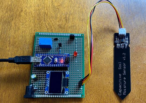
You can assemble all the components on Zero PCB as per the circuit diagram above. For the Water Pump Motor, a pipe can be fixed which can draw water.
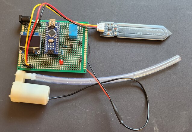
After assembling all components connect the Soil Moisture Sensor and Water Pump to the Board.
Source Code/Program
The code for Automatic Plant Watering System with Arduino & Soil Moisture Sensor project is written in Arduino IDE. The code requires Adafruit SSD1306 library for compilation.
Copy the following code and paste it on your Arduino IDE.
|
1 2 3 4 5 6 7 8 9 10 11 12 13 14 15 16 17 18 19 20 21 22 23 24 25 26 27 28 29 30 31 32 33 34 35 36 37 38 39 40 41 42 43 44 45 46 47 48 49 50 51 52 53 54 55 56 57 58 59 60 61 62 63 64 65 66 67 68 69 70 71 72 73 74 75 76 77 78 79 80 81 82 83 84 85 86 87 88 89 90 91 92 93 94 95 96 |
#include <Adafruit_SSD1306.h> // Include the Adafruit SSD1306 library to interact with the display #define SCREEN_WIDTH 128 // Set the width and height of the display in pixels #define SCREEN_HEIGHT 64 #define OLED_RESET -1 // Set the OLED reset pin to -1 if it shares the Arduino reset pin #define SCREEN_ADDRESS 0x3C // Set the address of the screen as specified in its datasheet // Create an Adafruit_SSD1306 object called display Adafruit_SSD1306 display(SCREEN_WIDTH, SCREEN_HEIGHT, &Wire, OLED_RESET); const int AirValue = 543; // Analog Value when Sensor is exposed to dry air const int WaterValue = 301; // Analog Value when Sensor is kept in water const int SensorPin = A0; // Analog pin where the sensor is connected // Variables to hold sensor values int soilMoistureValue = 0; int soilmoisturepercent = 0; int relaypin = 2; // Pin where the relay is connected void setup() { Serial.begin(9600); // Begin serial communication at 9600 bps pinMode(relaypin, OUTPUT); // Set the relay pin as an output digitalWrite(relaypin, LOW); // Start with the relay off delay(500); // Start the display, looping forever if it fails if (!display.begin(SSD1306_SWITCHCAPVCC, SCREEN_ADDRESS)) { Serial.println(F("SSD1306 allocation failed")); for (;;); } display.clearDisplay(); // Clear the display and display the cleared screen display.display(); delay(500); } // Function to update the display and control the relay based on soil moisture void updateDisplayAndRelay() { const char* motorStatus = (soilmoisturepercent <= 40) ? "ON" : "OFF"; // Set the motor status based on the soil moisture if (soilmoisturepercent <= 40) // Control the relay based on the soil moisture { digitalWrite(relaypin, HIGH); } else { digitalWrite(relaypin, LOW); } // Clear the display and set the text color display.clearDisplay(); display.setTextColor(SSD1306_WHITE); // Display the soil moisture display.setCursor(20, 0); display.setTextSize(1); display.print("Soil Moisture: "); display.setCursor(50, 20); display.setTextSize(2); display.print(soilmoisturepercent); display.setTextSize(1); display.print("%"); // Display the motor status display.setCursor(30, 45); display.setTextSize(1); display.print("Motor: "); display.print(motorStatus); // Update the display with the new text display.display(); // Print the soil moisture and motor status to the serial monitor Serial.print("Soil moisture: "); Serial.print(soilmoisturepercent); Serial.println("%"); Serial.print("Motor is "); Serial.println(motorStatus); delay(250); } void loop() { soilMoistureValue = analogRead(SensorPin); // Read the value from the soil moisture sensor Serial.println(soilMoistureValue); // Print the sensor value to the serial monitor soilmoisturepercent = map(soilMoistureValue, AirValue, WaterValue, 0, 100); // Map the sensor value to a soil moisture percentage soilmoisturepercent = constrain(soilmoisturepercent, 0, 100); // Ensure soilmoisturepercent is between 0 and 100 updateDisplayAndRelay(); // Update the display and control the relay based on the soil moisture delay(100); } |
From the tools Menu, Select Arduino Nano Board and its COM Port. Then you can upload the code.
Finding Soil Moisture Analog Values in Air & Water
From the above code you need to determine what the analog values read by Arduino Analog Pin when sensor is kept in Water and Air.
|
1 2 |
const int AirValue = 543; // Analog Value when Sensor is exposed to dry air const int WaterValue = 301; // Analog Value when Sensor is kept in water |
These values need to be pracitcally determined.
Therefore copy the following code below and upload it to the Arduino Nano Board.
|
1 2 3 4 5 6 7 8 9 10 11 12 13 14 15 16 17 |
const int SensorPin = A0; // Analog pin where the sensor is connected int soilMoistureValue = 0; void setup() { Serial.begin(9600); // Begin serial communication at 9600 bps delay(500); } void loop() { soilMoistureValue = analogRead(SensorPin); // Read the value from the soil moisture sensor Serial.print("Soil Analog Value: "); // Print the sensor value to the serial monitor Serial.println(soilMoistureValue); delay(100); } |
After uploading the code, open the Serial Monitor.
First keep the Soil Moisture Sensor exposed to dry air.
Now observe the value in Serial Monitor.
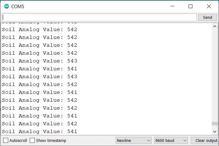
In our case, the analog value we got is 543. Replace this value in the main code part.
Now put the Soil Moisture sensor in water.

Again observe the value in Serial Monitor and keep watching until the value become stable.
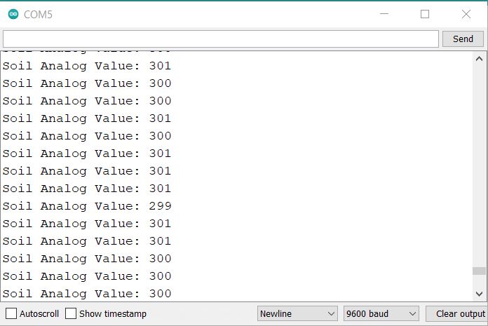
In our case, the analog value we got for water part is 301. Replace this value in the main code part.
Testing & Demo
Once the reading are calibrated and correct code is uploaded, its time to test the project.
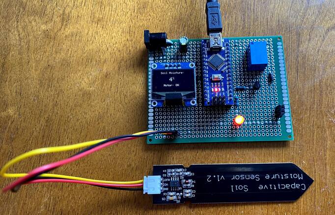
The OLED will display the value around 0% when sensor is placed in dry air. In this case the Motor is turned ON as the Threshold is set to 40%. The Motor status is displayed on OLED Display.
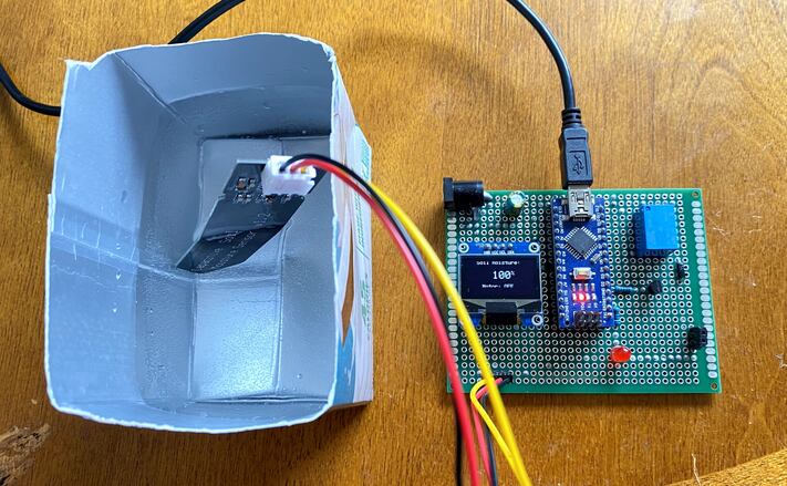
The OLED now display 100% Soil Moisture value when placed in Water. In this case the Motor is turend off and its status is displayed on OLED Display.
Now you can dip the Soil Moisture Sensor in Soil Pot. Also keep the end of the watering pipe in the pot.

If the Sensor detects the level of Water below 40%, the Motor turns ON and starts watering the plant. When the Soil Moisture reaches 40%, the motor turns off.

The motor won’t turn up until the Soil Moisture reaches 40%. You can setup the threshold in the code.
Conclusion:
In conclusion, the Automatic Plant Watering System harnesses the power of the Arduino and the precision of a Capacitive Soil Moisture Sensor to ensure optimal watering for plants. No longer will plants face the risks of being under or over-watered. With real-time moisture level data displayed on an OLED screen, users are kept informed not only about the soil’s condition but also about the active status of the watering motor. This comprehensive guide has equipped you with the knowledge to integrate these technologies, ultimately ensuring your plants thrive with the right amount of hydration.

")


1 Comment
does the assembly of the components require gluing them into the board?