

In this tutorial we will design a circuit using TRIAC and optocoupler to make a 220V Wireless AC Light Dimmer with Android Bluetooth & Arduino.
WARNING: This circuit is connected directly to the mains AC voltage. You must care about all safety precautions before using the device. If you are a beginner and without having the idea of using electronics appliances. Please avoid!
Overview
We have AC loads everywhere around us. And most of the home appliances are supplied with the AC mains power. There is plenty of situations that we want to have full control over an AC load such as a dimming of a lamp, speed control of AC motor/Fan, Vacuum Cleaner Control and so many other applications. The proper way to control dimming 230v AC is through phase control with a Triac: the Triac then is fully opened, but only during a part of the sinus AC wave.

But the controlling an AC load is not as easy as controlling a DC load. The electronics circuit for both these applications is different. The AC mains with a sinusoidal wave has the frequency of 50Hz. To build an AC dimmer, the zero-crossing points (the points where the wave changes its polarity) are important. To detect these points, we have to build a zero-crossing detector first. Similarly, we have to control the phase and cycle of the waveform. Since every component can’t tolerate 220V AC, so we need to isolate the circuit from 220V AC using some other component. The whole process is explained below.
Before moving ahead you can check our previous AC Dimmer Project and also the simple PWM Lamp Dimmer project.
.
Bill of Materials
Following are the components required to make the AC Dimmer Project. All the components can be easily purchased from Amazon.
| S.N. | Components Name | Quantity | Purchase Links |
|---|---|---|---|
| 1 | Arduino Nano Board | 1 | Amazon | AliExpress |
| 2 | Optocoupler IC EL817/PC817 | 1 | Amazon | AliExpress |
| 3 | Optoisolator MOC3020 | 1 | Amazon | AliExpress |
| 4 | TRIAC BTA16 | 1 | Amazon | AliExpress |
| 5 | Diode 1N4007 | 4 | Amazon | AliExpress |
| 6 | Bluetooth Module HC-05 | 1 | Amazon | AliExpress |
| 7 | Resistors 47K | 2 | Amazon | AliExpress |
| 8 | Resistor 1K | 1 | Amazon | AliExpress |
| 9 | Resistor 100-ohm | 1 | Amazon | AliExpress |
| 10 | Bulb 100W | 1 | - |
Circuit: Wireless AC Light Dimmer with Bluetooth TRIAC & Arduino
Here is a circuit diagram for 220V Wireless AC Light Dimmer with Android Bluetooth, TRIAC & Arduino. The schematic has been designed using EasyEDA online PCB Designing tool.

The circuit is divided into 4 parts:
1. Zero Cross Detector Circuit
2. Phase/Angle Control Using Triac
3. Bluetooth to Control the Dimming
4. The Arduino Code for changing delay in mS
1. Zero Cross Detector Circuit
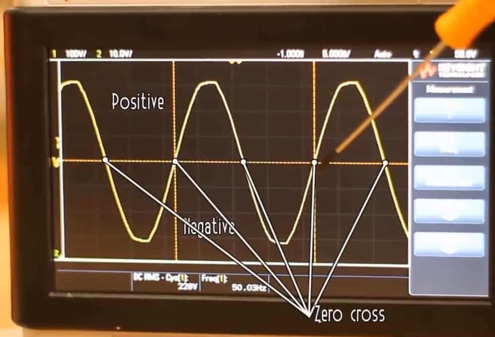
The AC voltage that we get from home supply is around 310 volts peak to peak or 220V RMS. The frequency is usually between 50 – 60 HZ. We have a positive part and a negative one so there will be a zero-crossing. So we will have to detect that zero-cross since our pulse needs to be in phase with the AC voltage

So, we have to detect when the voltage passes from positive to negative or from negative to positive and synchronize our pulse with that so it will fire always in the same spot. For that, we will use a full bridge rectifier. This will give the output both the positive and negative curves of the AC wave.
There are two 47 kilo-ohms resistors to limit the current. And to separate the high voltage side from the low voltage side, we will use an EL817 optocoupler. In this way, there is no direct connection between 220V high voltage and 5V of the Arduino.
2. Phase/Angle Control Using Triac
Using a component called TRIAC, we will control the amount of time that this power is ON and OFF. But before that, we need to understand the working of TRIAC.
We are aware of the diode. When we put a single diode to an AC signal, we get a half-wave rectifier. With just one diode, the positive part of AC waveform remains & the negative part is chopped.

So we want to control the diode by activating it or deactivating it. So this can be done by using a THYRISTOR, which basically is a controlled diode that will be activated when the gate receives a current trigger and continuing to conduct while the voltage across the device is not reversed.
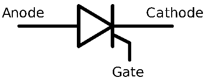
So here we have our AC signal. The negative part won’t pass if we use a diode and on the positive part, if we don’t switch the THYRISTOR there won’t be the positive part either. Suppose if we have to activate the gate of the THYRISTOR with a pulse in the middle position and let the remaining part of the positive side of the AC wave. So we get the only positive part as a rectified output. But if we want to do this with both positive and negative sides, we should use two THYRISTORS in an antiparallel configuration. But we already have that component which can do this work, that’s called TRIAC. The TRIAC will remain deactivated until it receives a pulse at its gate. Once received, it will remain activated until the main input will change its polarity. So we will use BTA16 TRIAC to control AC voltage.

First we have to detect the zero-cross since the pulse needs to be in phase with the AC voltage. So, we have to detect when the voltage passes from positive to negative or from negative to positive and synchronize our pulse with that so it will fire always in the same spot. For this full-bridge rectifier is used which will give the output both the positive and negative curves of the AC wave.
3. Bluetooth to Control the Dimming
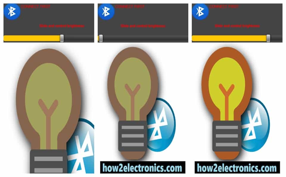
In order to control power, all we have to do is to control the time between the zero-cross and when we fire the pulse at the TRIAC gate. So we will use UART Communication through Bluetooth HC-05/HC-06 to change the delay timing. The android app that is designed through MIT App Inventor has a slider in it. Sliding the slider is like changing the value of delay serially though Arduino. The Arduino code will read the value from Android app and map that value to a delay between 1 and 10 milliseconds.
Source Code/Program
The Arduino Program for Wireless AC Light Dimmer with Android Bluetooth & Arduino is given below with comments to understand the AC Dimmer working. Simply upload this code to your Arduino board.
|
1 2 3 4 5 6 7 8 9 10 11 12 13 14 15 16 17 18 19 20 21 22 23 24 25 26 27 28 29 30 31 32 33 34 35 36 37 38 39 40 41 42 43 44 45 46 47 48 49 50 51 52 53 54 55 56 57 |
int mydelay = 0; int myvalue=0; int last_CH1_state = 0; void setup() { /* * Port registers allow for lower-level and faster manipulation of the i/o pins of the microcontroller on an Arduino board. * The chips used on the Arduino board (the ATmega8 and ATmega168) have three ports: -B (digital pin 8 to 13) -C (analog input pins) -D (digital pins 0 to 7) //All Arduino (Atmega) digital pins are inputs when you begin... */ PCICR |= (1 << PCIE0); //enable PCMSK0 scan PCMSK0 |= (1 << PCINT0); //Set pin D8 trigger an interrupt on state change. Input from optocoupler pinMode(3,OUTPUT); //Define D3 as output for the DIAC pulse Serial.begin(9600); //Start serial com with the BT module (RX and TX pins) } void loop() { //Read the value of the pot and map it from 10 to 10.000 us. AC frequency is 50Hz, so period is 20ms. We want to control the power //of each half period, so the maximum is 10ms or 10.000us. In my case I've maped it up to 7.200us since 10.000 was too much if(Serial.available()>0) { myvalue = map(Serial.read(),0,255,10000,10); //In my case I've used myvalue = map(Serial.read(),0,255,7000,10); for better results } if (mydelay) { delayMicroseconds(myvalue); //This delay controls the power digitalWrite(3,HIGH); delayMicroseconds(100); digitalWrite(3,LOW); mydelay=0; } } //This is the interruption routine //---------------------------------------------- ISR(PCINT0_vect) { ///////////////////////////////////// //Input from optocoupler if(PINB & B00000001){ //We make an AND with the pin state register, We verify if pin 8 is HIGH??? if(last_CH1_state == 0){ //If the last state was 0, then we have a state change... mydelay=1; //We haev detected a state change! } } else if(last_CH1_state == 1){ //If pin 8 is LOW and the last state was HIGH then we have a state change mydelay=1; //We haev detected a state change! last_CH1_state = 0; //Store the current state into the last state for the next loop } } |
PCB Designing, Gerber File & PCB Ordering Online
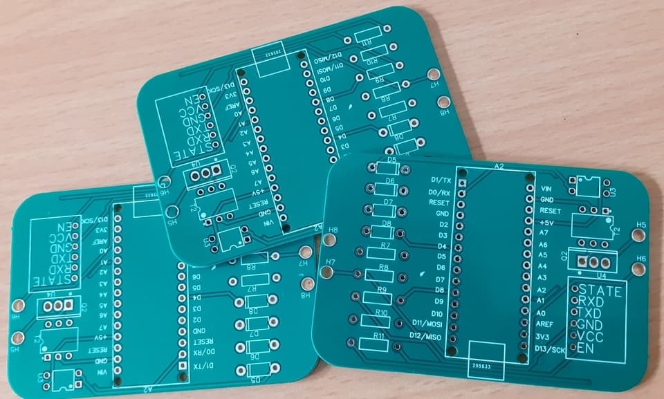
The PCB for AC Dimmer has been designed in EasyEDA online PCB making tool. Below is the front view and Back View of the PCB.

The Gerber File for the PCB is given below. A quick way to prototype this PCB project is to use ALLPCB. This company has this limited-time sale offering 5 pieces of PCB for only 1$. You can simply download the Gerber File and upload it in ALLPCB.
You can use this Gerber file to order high-quality PCBs for this project. To do that visit the ALLPCB official website by clicking here: https://www.allpcb.com/.

You can now upload the Gerber File by choosing the Quote Now option. You can choose the Material Type, Dimensions, Quantity, Thickness, Solder Mask Color, and other required parameters from these options.

After filling all details, select your country and shipping method. Finally you can place the order.
So after almost 5 days, I got the PCB from ALLPCB.

The PCB quality from ALLPCB is superb with very high quality.
I have been using ALLPCB for my project for two years now. They have been very consistent on quality and I never had any unsatisfactory board with them.
After that you can solder all the necessary components as per circuit diagram and make the final product ready.

Now you can power ON the circuit and start testing the working by sliding the slider in the Android App. You can use CFL Bulb or simply Filament Bulb to do the testings. I got the result from zero brightness to full brightness.


AC Dimmer Android App
The Android App for dimming the Bulb/Lamp has UI given below. The slider button on the App is used to Control the brightness.
The App is designed using MIT App Inventor 2. You can directly download the app from the below link or you may import the .aia file and modify the app according to your requirements.

AC Dimmer Android App: Download
AC Dimmer .aia File: Download

")


