

Overview
In this article, we will make Light Dimmer Circuit using 555 Timer IC & MOSFET. A light dimmer is an electronic device used to control the brightness of a light source, such as incandescent, halogen, or LED lamps. It allows users to adjust the intensity of the light to create different moods or conserve energy.
This 12V LED dimming circuit utilizes a 555 timer IC, providing an easy way to control LED brightness with a potentiometer. The 555 PWM LED dimmer circuit generates a PWM signal, and the potentiometer allows for duty cycle adjustments. Using PWM for brightness control makes this dimmable LED light highly efficient, and the circuit can be assembled using just a few basic electronic components.
You may try some previous circuits:
- Simple PWM Lamp Dimmer
- Wireless AC Light Dimmer
- TRIAC Based 220v AC Dimmer
- IoT AC Dimmer with ESP32 WebServer
Components Required
- 555 Timer IC – 1
- IRFZ44N MOSFET – 1
- 50K Potentiometer – 1
- 0.1uF Ceramic Capacitors – 2
- 1K Resistors – 2
- 1N4007 Diode – 2
- Breadboard
- 12V DC power supply
- 12V LED strip
Circuit & PCB Design
The following is the LED Light Dimmer Circuit designed using 555 Timer IC & IRFZ44N MOSFET.

The 555 Timer IC is configured in Astable Multivirabtor Mode.
Here is the PCB for this project designed using EasyEDA Software.

The Gerber File for the PCB is given below. You can simply download the Gerber File and order the PCB from ALLPCB at 1$ only.
This is the 3D view of the PCB which looks awesome.

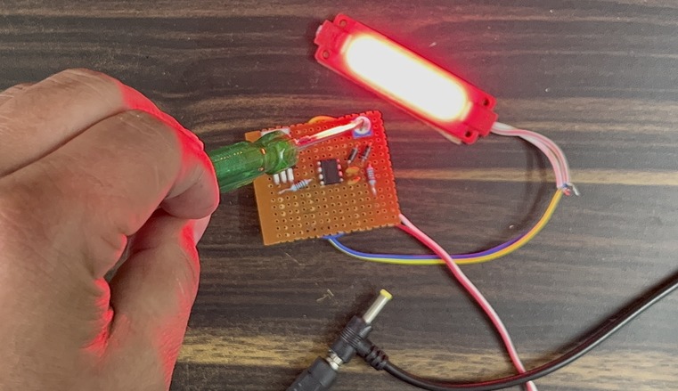
For testing purposes I used Vero Board and assembled all the components there.

The backside of the PCB looks too messy due to jumper wires and other connections.

Power the circuit using a 12V Battery. Connect the 12V LED Lamp at the output terminal of the circuit.

Working of Light Dimmer Circuit using 555 Timer
The light dimmer circuit discussed here uses a 555 timer IC and MOSFET to control the brightness of an LED strip. The workings of the circuit are as follows:

The 555 timer is configured in an astable mode, generating a square wave with adjustable high and low times. The ratio of these high and low times can be modified by altering the values of resistors R1 and RV1, as well as capacitor C2 in the standard 555 astable configuration.
In this particular circuit, RV1 is a 50k potentiometer that serves as a variable resistor, allowing for adjustment of the duty cycle of the output signal. Capacitor C2 charges through diode D1 and discharges through diode D2. This process creates a pulse-width modulation (PWM) signal at the output pin (pin 3) of the 555 timer. As a result, the MOSFET switches on and off according to the PWM signal.
The duration of the high state (ON time) in the square wave can be calculated using the formula:
The duration of the low state (OFF time) in the square wave can be calculated using the formula:

By adjusting the potentiometer (RV1), the duty cycle of the PWM signal changes, in turn altering the brightness of the connected LED strip. The MOSFET acts as a switch, enabling or disabling the current flow through the LED strip based on the PWM signal.
This method of controlling the LED brightness is energy-efficient and provides smooth transitions between different levels of light intensity.


3 Comments
very nice project how I could replace the pot with a rain sensor and increase the dutu suckle accordingly
your light dimmer circuit using 555 IC and MOSFET is not working. we had used exactly the same components. Highly disappointed
Maybe you can reverse either D1 or D1…
According to this schematic C2 can only accumulate charge via R2, D1, D2 and RV1 (upper and lower parts in parallel). The discharge of C2 is blocked by both D1 and D1.
So by reversing one of them (let’s say D1) C2 will be charged via R2, D2 and lower part of RV1.
When voltage of C2 gets to Threshold Level it will discharge via upper part of RV1.
The cycle will repeat once voltage of C2 drop to Trigger level.
Thus you’ll have T1 = C2(R2 +pRV1) and T2 = C2(1-p)RV1 (T1, T2 being ON and OFF time intervals)
The total cycle period is T = T1 + T2 = C2 * (R2 + RV1) = constant
Different positions of RV1 wiper give different T1 and T2 resulting in different perceived illumination of an LED or different rotation speed of a DC motor.