

Overview
In this project, we will build an IoT Relay using Raspberry Pi Pico W WiFi and control the Relay via a Web Server. We will use Thonny IDE to program the Raspberry Pi Pico W using MicroPython Code. It’s a great way to build a Wi-Fi switch to turn on and off any electrical device spending very little money.
This DIY IoT Relay based on the Raspberry Pi Pico W WiFi + Bluetooth module can be used to control High Power Devices like Water Pumps, Air Conditioners, Heaters, and other High Ampere loads. The best thing about this IoT Relay is that it can be controlled remotely in a local network using WiFi technology. The cell phone or any web application can be used to access the Web Server. Using the web page, you can turn ON/OFF any appliances at your home.
Bill of Materials
To control the Relay using the Raspberry Pi Pico W Web server, we need the following components. You can purchase them from the following links.
| S.N. | Components | Quantity | Purchase Link |
|---|---|---|---|
| 1 | Raspberry Pi Pico W | 1 | Amazon | AliExpress |
| 2 | 1 Channel Relay | 1 | Amazon | AliExpress |
| 3 | AC Bulb | 1 | - |
| 4 | Breadboard | 1 | Amazon | AliExpress |
| 5 | Connecting Wires | 1 | Amazon | AliExpress |
| 6 | Micro-USB Cable | 1 | Amazon | AliExpress |
Relays & Relay Module
A relay module is an electrical switch that is operated by an electromagnet. The electromagnet is activated by a separate low-power signal from a microcontroller. When activated, the electromagnet pulls to either open or close an electrical circuit.

The relay can be activated via 3.3V or 5V of a microcontroller like Raspberry Pi Pico W. This allows to control of appliances operating at 12V, 24V, 110V, or 220V AC.
There are single-channel or multiple-channel relays available in the market. The multiple-channel relay includes 1, 2, 4, 8, 16 Channels.

Some relay module comes with a built-in optocoupler that optically isolate the Microcontroller boards from the relay circuit and protect the microcontrollers.
Most of the Relay Module has 6 pins, 3 on each side. The VCC, GND & Input pin is used with Microcontroller. The NO, Common & NC is used with High Voltage Electrical Appliances.

| Pin Number | Pin Name | Description |
| 1 | Relay Trigger | Input to activate the relay |
| 2 | Ground | 0V reference |
| 3 | VCC | Supply input for powering the relay coil |
| 4 | Normally Open | Normally open terminal of the relay |
| 5 | Common | Common terminal of the relay |
| 6 | Normally Closed | Normally closed contact of the relay |
Circuit Diagram & Connections
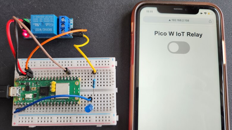
Let us see how we can connect the single-channel Relay Module to Raspberry Pi Pico W. The connection diagram is fairly simple.

Connect the VCC, GND & Input pin of the Relay to 3.3V, GND & GP18 of Pi Pico W. Connect any electrical appliances like a fan or bulb at the output of the Relay Module. The electrical appliances work at 110/220V.

In this example, we’re controlling a lamp & it is advised to use a normally open configuration as in the image above.
Project PCB Gerber File & PCB Ordering Online
If you don’t want to assemble the circuit on a breadboard and you want PCB for the project, then here is the PCB for you. I used EasyEDA to draw the schematic first.

Then I converted the schematic to PCB. The PCB Board for this project looks something like below.

The Gerber File for the PCB is given below. You can simply download the Gerber File and order the PCB from ALLPCB at 1$ only.
You can use this Gerber file to order high quality PCB for this project. To do that visit the ALLPCB official website by clicking here: https://www.allpcb.com/.

You can now upload the Gerber File by choosing the Quote Now option. From these options, you can choose the Material Type, Dimensions, Quantity, Thickness, Solder Mask Color and other required parameters.

After filling all details, select your country and shipping method. Finally you can place the order.

You can assemble the components on the PCB Board.
MicroPython Code to Control a Relay Module
The following code is used to control a relay with the Raspberry Pi Pico W. It is as simple as controlling an LED or any other output. We will use a normally open configuration.
When we send a LOW signal to GP18, the Relay will turn ON. Similarly sending a HIGH signal to GP18 will turn OFF the relay.
|
1 2 3 4 5 6 7 8 9 10 |
from machine import Pin import utime relay=Pin(18,Pin.OUT) while True: relay.value(1) #Set relay turn on utime.sleep(5) relay.value(0) #Set relay turn off utime.sleep(5) |
After running the code, you will see Relay turning ON and OFF after every 5 seconds.
MicroPython Code to Control a Relay Module via Web Server
In this MicroPython Code, we’ve created a Web Server script that allows you to control a relay remotely using a Raspberry Pi Pico W Local IP Address & web page.
Before running the code, from the following lines change the WiFi SSID and password.
|
1 |
wlan.connect("***********","***********") # ssid, password |
Save the code to Raspberry Pi Pico W memory and give it any name like main.py.
|
1 2 3 4 5 6 7 8 9 10 11 12 13 14 15 16 17 18 19 20 21 22 23 24 25 26 27 28 29 30 31 32 33 34 35 36 37 38 39 40 41 42 43 44 45 46 47 48 49 50 51 52 53 54 55 56 57 58 59 60 61 62 63 64 65 66 67 68 69 70 71 72 73 74 75 76 77 78 79 80 |
from machine import Pin import network import time try: import usocket as socket except: import socket relay=Pin(18,Pin.OUT) wlan = network.WLAN(network.STA_IF) wlan.active(True) wlan.connect("***********","***********") # ssid, password # connect the network wait = 10 while wait > 0: if wlan.status() < 0 or wlan.status() >= 3: break wait -= 1 print('waiting for connection...') time.sleep(1) # Handle connection error if wlan.status() != 3: raise RuntimeError('wifi connection failed') else: print('connected') ip=wlan.ifconfig()[0] print('IP: ', ip) def web_server(): if relay.value() == 1: relay_state = '' else: relay_state = 'checked' html = """<html><head><meta name="viewport" content="width=device-width, initial-scale=1"><style> body{font-family:Arial; text-align: center; margin: 0px auto; padding-top:30px;} .switch{position:relative;display:inline-block;width:120px;height:68px}.switch input{display:none} .slider{position:absolute;top:0;left:0;right:0;bottom:0;background-color:#ccc;border-radius:34px} .slider:before{position:absolute;content:"";height:52px;width:52px;left:8px;bottom:8px;background-color:#fff;-webkit-transition:.4s;transition:.4s;border-radius:68px} input:checked+.slider{background-color:#2196F3} input:checked+.slider:before{-webkit-transform:translateX(52px);-ms-transform:translateX(52px);transform:translateX(52px)} </style><script>function toggleCheckbox(element) { var xhr = new XMLHttpRequest(); if(element.checked){ xhr.open("GET", "/?relay=on", true); } else { xhr.open("GET", "/?relay=off", true); } xhr.send(); }</script></head><body> <h1>Pico W IoT Relay Control</h1><label class="switch"><input type="checkbox" onchange="toggleCheckbox(this)" %s><span class="slider"> </span></label></body></html>""" % (relay_state) return html s = socket.socket(socket.AF_INET, socket.SOCK_STREAM) s.bind(('', 80)) s.listen(5) while True: try: conn, addr = s.accept() conn.settimeout(3.0) print('Got a connection from %s' % str(addr)) request = conn.recv(1024) conn.settimeout(None) request = str(request) print('Content = %s' % request) relay_on = request.find('/?relay=on') relay_off = request.find('/?relay=off') if relay_on == 6: print('RELAY ON') relay.value(0) if relay_off == 6: print('RELAY OFF') relay.value(1) response = web_server() conn.send('HTTP/1.1 200 OK\n') conn.send('Content-Type: text/html\n') conn.send('Connection: close\n\n') conn.sendall(response) conn.close() except OSError as e: conn.close() print('Connection closed') |
Testing IoT Relay using Raspberry Pi Pico W Web Server
After running the Code, the Thonny Shell will display the local IP Address of Raspberry Pi Pico W.
Copy the IP Address and paste it on any Web Browser. A page will appear as shown below.

You can slide the switch from the off position on the web page, and the relay will turn on immediately. In this case, we are making an HTTP request on GET /?relay=on HTTP/1-IP-address/on. This request returns a webpage with the changed GP16 state on it.

Sliding the switch again from the on position to the off position will turn off the relay again. In this case. we are making a request on the Pico W IP address, followed by /?GET /?relay=off The LED turns off, and the GP16 state is updated.
The Thonny Shell window will display the following message.
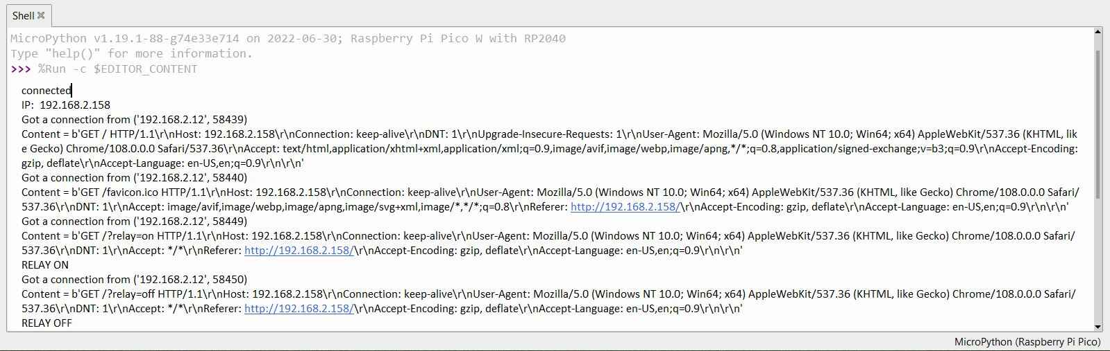
This is the easiest method to control any home appliances via a Relay module using Raspberry Pi Pico W Web Server.


4 Comments
Thanks for the guide! Do all relays support 3.3v or do you need to find one specifically for that? I read somewhere that some relay may not get enough power with 3.3 to energize the coils…
Using a transistor you can turn any relay whether 5v ir 3.3V.
I tried this project and it worked great. Do you have any example on how to create two buttons slide to turn on two different relays?
I have the same problem to connect the relay module to Wi-Fi. But, can i get the same code which can run on Arduino ide.
Thank you