

Overview
In this project we will build a DIY Customized Mini PC using Raspberry Pi 4 and Sunfounder Pironman Mini PC Kit. The Pironman is a SunFounder’s customized Mini PC for Raspberry Pi. All you need is to connect the screen, mouse, and keyboard, and you can use it for projects, entertainment, and office.

The build DIY Raspberry Pi 4 Mini PC has following features:
- Small size of 4.43’’ x 2.69’’ x 4.68’’
- Raspberry Pi mini PC
- The tower cooler can cool a 100% CPU load Pi to 39°C at 25°C room temperature
- 0.96” OLED Display showing CPU usage, temperature, disk usage, IP address, RAM usage
- Onboard USB to M.2 SATA SSD, TRIM supported
- RGB Fan, with GPIO control
- 16 WS2812 Addressable RGB LEDs
- IR Receiver for a multi-media center like Kodi or Volumio
- External GPIO extender with pin name label
- Power status memory, remembers power status, automatically boots after accident power cut off
- Aluminum main body with clear Acrylic side panel
Read about: A Complete Raspberry Pi System Monitor for PC
Components Required
We need the following components to build this DIY Raspberry Pi 4 Mini PC System:
| S.N. | Components | Quantity | Purchase Link |
|---|---|---|---|
| 1 | Raspberry Pi 4 | 1 | Amazon | SunFounder |
| 2 | Pironman Mini PC Kit | 1 | Amazon | SunFounder |
| 3 | SD Card 16/32 GB | 1 | Amazon | SunFounder |
| 4 | 7 inch Display or HDMI Screen | 1 | Amazon | SunFounder |
| 5 | 5V, 3A DC Adapter for RPi | 1 | Amazon | SunFounder |
| 6 | Mouse & Keyboard | 1 | Amazon | SunFounder |

Apart from all this you may require a Micro HDMI Cable and Sound or Earphone plugins or some additional 7 inch Display.
Hardware Assembly
The Pironman Kit has all the necessary hardware and tools to build a DIY Mini PC.

The kit comes with an instruction manual that guides how you can assemble all the parts together to build a complete PC Setup.
The instruction manual consists of 4 pages. All 4 pages have a diagrammatic view and a well-demonstrated instruction guide that can easily help you to assemble the Pironman Kit.
The front side of the AssembleD kit looks something like this.
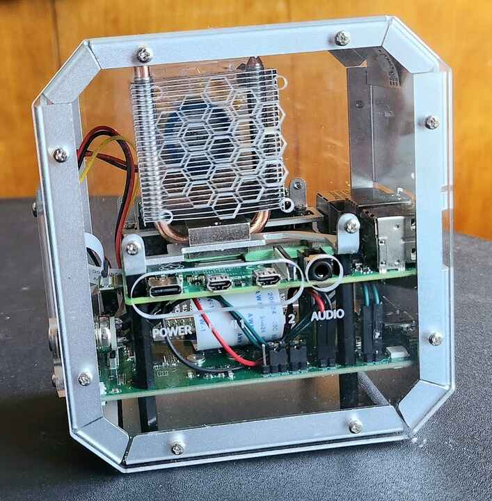
From the transparent case, you can view all the internal parts clearly. The HDMI port 1 and 2 can be connected via this end. You can supply the power through the type C USB port here. The 3.5mm audio jack is available for audio functionality and speaker functions.
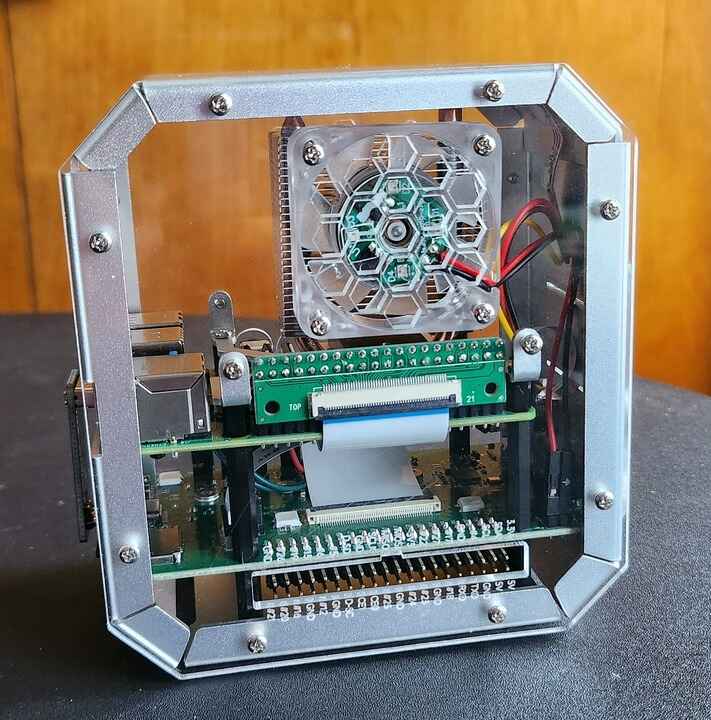
The backside of the Kit has all the necessary GPIO ports output to connect the sensors modules and other active passive electronic components.
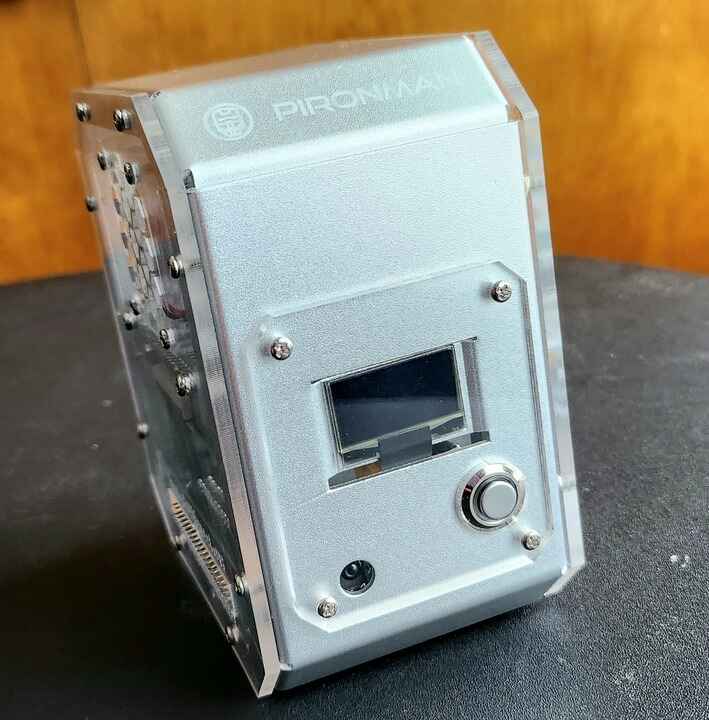
The left side of the kit has OLED Display that can display CPU/RAM/ROM Usage, CPU Temperature, and IP address. Similarly, a button is given to turn ON/OFF the Raspberry Pi 4 Mini PC.
The right side of the kit has all the USB Ports and ethernet ports. An onboard USB to M.2 SATA SSD, TRIM Supported is also available as shown in the image below.

Raspberry Pi OS Installation & Setup
The Raspberry Pi is a low-cost, computer that plugs into a computer monitor or TV, and uses a standard keyboard and mouse. It is also used as a tool to learn Python programming.
Before moving to the project part, we need to set up the Raspberry Pi Board. For this, you need a 16/32 GB SD Card. We need to install OS to the system stored in SD Card.
The OS installation part and setup part can be followed on Raspberry Pi OS Setup.
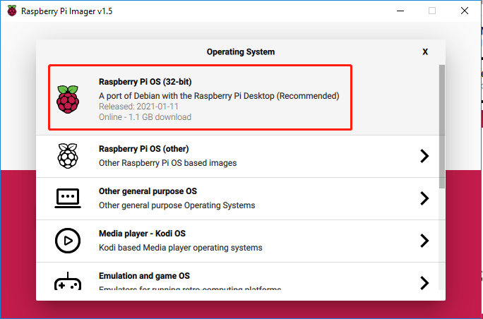
You can either use the HDMI Screen or enable SSH and connect the Raspberry Pi to VNC Viewer using the local IP Address, username, and password.
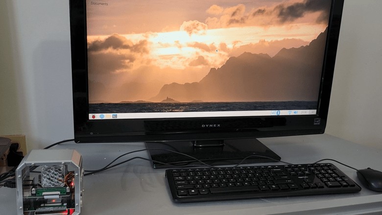
In my case, I am using the HDMI Screen to connect to my Raspberry Pi. I also connected Mouse and Keyboard to the USB port of the Pironman Kit.
Set up the Pironman
Now let us setup the DIY Mini PC based on Raspberry Pi 4 & Sunfounder Pironman kit. This Pironman is used in the same way as PC and requires the power button to power on/off.
Change the config.txt
Before you can start using Pironman, you need to configure the power button and the IR receiver.
Open the /boot/config.txt file with the following command.
|
1 |
sudo nano /boot/config.txt |
Add the following text to the end of the file, noting that there should be no spaces on either side of the =.
|
1 2 |
dtoverlay=gpio-poweroff,gpio_pin=26,active_low=0 dtoverlay=gpio-ir,gpio_pin=13 |
Press Ctrl+X -> Y -> Enter to save and exit editing.
Install pironman module
Use the following commands to download and install the pironman module.
|
1 2 3 4 |
cd ~ git clone https://github.com/sunfounder/pironman.git cd ~/pironman sudo python3 install.py |
After installation, the program will start automatically. Here are the basic configurations for Pironman.
- The OLED screen will display the CPU, RAM and ROM Usage, CPU Temperature and IP Address of the Raspberry Pi.
- After 60 seconds, the OLED display goes into sleep mode, and you can wake it up by a short press on the power button.
- The fan is turned on at 50 degrees Celsius.
- Turn on the WS2812 RGB strip so that it displays in color #0a1aff(blue) and in breath mode (change rate is 50%).
- At this point, you can press and hold for 2 seconds to safely shut down or 10 seconds to forcibly shut down.
Modify the Configuration
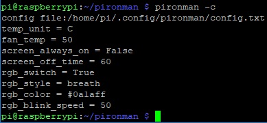
In the pironman module, we have some basic configurations for Pironman, and you can check them with the following command.
|
1 |
pironman -c |
The current configurations are shown below.
- The fan is turned on at 50 degrees Celsius.
- The duration of the OLED display is 60s, after 60s it will start to sleep.
- Turn on the WS2812 RGB strip so that it displays in color #0a1aff and in breath mode (change rate is 50%).
You can also modify these configurations to suit your needs.
Use pironman or pironman -h or pironman --help to view the instructions, as follows.
|
1 2 3 4 5 6 7 8 9 10 11 12 13 14 15 16 17 18 19 20 21 22 23 24 25 |
Usage: pironman <OPTION> <input> Options: start start pironman service stop stop pironman service restart restart pironman service -h,--help help, show this help -c,--check show all configurations -a,--auto [ on ],enable auto-start at boot [ off ], disable auto-start at boot -u,--unit [ C/F ], set the unit of temperature, C or F (Celsius/Fahrenheit) -f,--fan [ temp ], Temperature at which the fan switches on, in celsius (default 50),in range (30 ~ 80) -al,--always_on [on/off], whether the screen is always on, default False -s,--staty_time [time], screen display duration in second, in second, default 30 -rw,--rgb_sw [on/off], rgb strip switch -rs,--rgb_style rgb strip display style, default: breath, in [breath / leap / flow / raise_up] -rc,--rgb_color [(HEX)color], set the color of rgb strip, default: 0a1aff -rb,--rgb_speed [speed], rgb blink speed (0 ~ 100, default 50) |
For example, to turn off the automatic execution of programs at boot.
|
1 |
pironman -a off |
Or reset the color of WS2812 RGB strip.
|
1 |
pironman -rc ff8a40 |
Those configurations are stored in /.config/pironman/config.txt, and you can also make changes directly in this file.
|
1 |
sudo nano ~/.config/pironman/config.txt |
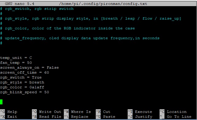
Press Ctrl+X -> Y -> Enter to save and exit editing.
About Sunfounder Pironman Raspberry Pi Mini PC

Features & Parameters
- Dimension: 112.45×68.2×118.92mm
-
- Material
-
- Main body: aluminum alloy
- Both sides and front panel: acrylic
- Support platform: Raspberry Pi 4B
- Power input: USB Type C 5V/3A
- Rated power: 5V/800mA
-
- interface (d ~ i is the original Raspberry Pi interface exposed)
-
- Raspberry Pi standard 40-Pin GPIO
- micro SD
- USB Type C power input
- USB 2.0 x 2
- USB 3.0
- Gigabit LAN port
- USB Type C Raspberry Pi power supply (direct power to Raspberry Pi, not recommended)
- micro HDMI x 2
- 3.5mm headphone jack
- Power button
- OLED screen: 0.96’’ 128×64 resolution
- Infrared receiver: 38KHz
- Cooling fan: size 40x40x10mm
- WS2812 RGB LED: 16xWS2812B-5050
- Shutdown Signal Pin: By pressing the power button, the Raspberry Pi will power off, while setting GPIO26 to a high level, and if the Main Board detects this high level, it will power cut.
Main Board

There are 5 jumper caps on the Main Board, and each jumper cap corresponds to a function, if you do not need the function and want to use the pin elsewhere, you can unplug the jumper cap. The following is a detailed explanation of the functions of the five jumper caps.
- Cooling Fan (IO6): The fan is constantly spinning when this jumper cap is unplugged. You can unplug the fan wires or remove the fan if you don’t need it.
- IR Receiver (IO13): If you pull out this jumper cap, the IR Receiver will not work.
- WS2812 Strip (IO12): If you pull out this jumper cap, the WS2812 Strip will not work.
- Shutdown Signal (IO26): The Mainboard powers on/off depending on the level of the
Statepin; whenStateis low, it powers on, and whenStateis high, it powers off.- You can only turn off the main board by pressing and holding the power button for 10 seconds if you connect GND and state with a jumper cap.
- If you connect
Stateand IO26 with a jumper cap, after configuration, the Raspberry Pi can control theStatepin through IO26. When Raspberry Pi is on,Statewill be set to low level, when Raspberry Pi is off,Statewill be set to a high level, so the motherboard and Raspberry Pi can power on/off synchronously.
- Power Button (IO16): If you pull out this jumper cap, the power button will not work. Besides, the power button is also used to wake up the OLED screen in Sleep Mode.
Power Cut Memory
When the Pironman suddenly loses power, the chip of the Main Board will record this state and will automatically power on the next time.
OLED Screen

After installation, the script will start automatically and the OLED screen will display the CPU, RAM, ROM Usage, CPU Temperature, and IP Address of the Raspberry Pi.
In order to extend the life of the OLED screen, OLED will turn off after 60 seconds by default and will light up by pressing the power button shortly. You can enable/disable this feature with the following command.
- set to sleep mode: “al” means “always on”. In sleep mode, short press the power button to wake up.
|
1 |
pironman -al off |
- set to always on mode:
|
1 |
pironman -al on |
- Set the duration in seconds,
|
1 |
pironman -s 60 |
- The above is what we set for the OLED screen, if you want to make the OLED screen display other information and effects, you can open
/opt/pironman/main.pyto modify and run it.Open this python script and modify its contents.
1sudo nano /opt/pironman/main.pyPress
Ctrl+X->Y->Enterto save and exit editing.Run it.
|
1 |
sudo python3 /opt/pironman/main.py |
Cooling Fan
The Cooling Fan is connected to GPIO6 (BCM).
The working status of the Cooling Fan is decided by the CPU temperature. When the CPU temperature reaches the set threshold, the fan spins, and if it is 2 degrees Celsius below the threshold, the fan is stopped.
- Set the temperature unit,
C: Celsius,F: Fahrenheit.
|
1 |
pironman -u C |
- Set the temperature at which the fan starts, for example, 40 degrees Celsius (the unit is set by you).
|
1 |
pironman -f 40 |
WS2812 RGB Strip
The WS2812 RGB Strip is connected to GPIO12.
The WS1812 RGB Strip is a light strip with 8 RGB LEDs that can be used to display Pironman’s status. You can use commands to make it turn on or off, or to modify its color (default is blue), display mode and change rate.
- Turn on the WS2812 RGB Strip.
|
1 |
pironman -rw on |
- Turn it off.
|
1 |
pironman -rw off |
- Change its color, using hexadecimal color values.
|
1 |
pironman -rc fe1a1a |
- Changing the display mode, there are four modes to choose from:
breath,leap,flow,raise_up.
|
1 |
pironman -rs leap |
- Change the speed of change (0 ~ 100%).
|
1 |
pironman -rb 80 |
Above are the effects we preset for WS2812 RGB Strip, if you want it to display other effects, you can open /opt/pironman/ws2812_RGB.py to modify and run it.
Open this python script and modify its contents.
|
1 |
sudo nano /opt/pironman/ws2812_RGB.py |
Press Ctrl+X -> Y -> Enter to save and exit editing.
Run it.
|
1 |
sudo python3 /opt/pironman/ws2812_RGB.py |
Power Button
The power button is connected to GPIO26, if you want to change it to another pin, please refer to Change the config.txt.
The power button can be used to wake up the OLED screen or to turn the Pironman off.
- Upon power-up, the OLED screen displays for 60 seconds before going into sleep mode. Using the power button, you can wake up the OLED screen again later.
- You have 2 ways to get the Pironman to shut down.
- Force Shutdown
Pressing and holding the power button for 10 seconds will let the Pironman power cut, but this method may damage the Raspberry Pi’s files or leave some changes unsaved.
- Safe Shutdown
There is also a way to safely turn off the Pironman by pressing and holding the power button for 2 seconds after configuring it.
- Force Shutdown
IR Receiver
The IR receiver is connected to GPIO13, if you want to change it to another pin, please refer to Change the config.txt.
Before you can use IR receiver, you need to test its connection and install the relevant module.
-
- Use the following command to test, if there is a display device then the configuration is successful.
|
1 |
sudo ls /dev |grep lirc |
-
- Install the
lircmodule.
- Install the
|
1 |
sudo apt-get install lirc -y |
- Run the following command, and if you press a key on the remote controller, the code of the corresponding key will be printed.
|
1 |
mode2 -d /dev/lirc0 |
M.2 SATA SSD

The M.2 SSD hard drive interface only supports SATA protocol, not NVME/PCIe.
In the Pironman’s mainboard, there is an M.2 SSD connector for installing your M.2 SATA SSD.
Various lengths of M.2 SATA SSD can be mounted: 22mm x 30mm, 42mm, 60mm, and 80mm, supporting SSD TRIM function.
Refer to M.2 SATA SSD documentation setup to use the M.2 SATA SSD.
Video Tutorial & Guide

You can setup various other functions using the tools and Python libraries to enhance your DIY Customized Mini PC using Raspberry Pi 4 & Sunfounder Pironman kit.


1 Comment
No such directory as “boot” and no such file as config.txt, so do I just create a config.txt file in the root directory. For step one “confused”
Thanks