

Overview
In this project, we will make Temperature Based Fan Speed Control & Monitoring System using ESP8266 WiFi Module & observe the data on IoT App Blynk. The fan speed increases based on the increase in temperature. The Blynk App will show the current temperature & Fan speed in percentage. Using the Blynk, we can also set the threshold value at what temperature the fan should turn ON.
To sense the room temperature, we will use a DS18B20 Waterproof Temperature Sensor. For the fan part, a 12V fan is perfect for this application as it is easy to control the speed with the PWM signal. The 16×2 LCD Display will display the instantaneous temperature and fan speed as well.
To get started, you can refer to Arduino Temperature Fan Speed Controller project, which gives overall idea about the working.
Bill of Materials
To make IoT Temperature Based Fan Speed Control System project, we need the following components.
| S.N. | Components | Quantity | Purchase Link |
|---|---|---|---|
| 1 | NodeMCU ESP8266 Module | 1 | Amazon | AliExpress |
| 2 | DS18B20 Temperature Sensor | 1 | Amazon | AliExpress |
| 3 | 16x2 LCD Display | 1 | Amazon | AliExpress |
| 4 | 10K Potentiometer | 1 | Amazon | AliExpress |
| 5 | IRF540N Mosfet | 1 | Amazon | AliExpress |
| 6 | 12V DC Fan | 1 | Amazon | AliExpress |
| 7 | 12V DC Power Adapter | 1 | Amazon | AliExpress |
| 8 | Resistor 10K | 1 | Amazon | AliExpress |
| 9 | Resistor 4.7K | 1 | Amazon | AliExpress |
| 10 | 7805 Voltage Regulator IC | 1 | Amazon | AliExpress |
| 11 | 100uF Capacitor | 1 | Amazon | AliExpress |
| 12 | 10uF Capacitor | 1 | Amazon | AliExpress |
| 13 | Breadboard | 1 | Amazon | AliExpress |
| 14 | Connecting Wires | 1 | Amazon | AliExpress |
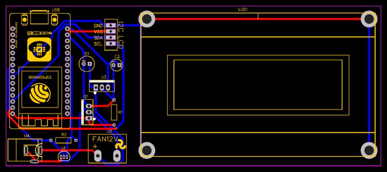
Circuit Diagram & Connection
The following is the schematic of the IoT Temperature Based Fan Speed Control & Monitoring System using ESP8266. The connections are fairly simple.

The entire circuit can be powered by a 12V DC power supply. Actually, the DC Fan only requires 12V for operations. The rest of the components takes 5V as input from the 7805 Voltage regulator IC. The DS18B20 Waterproof temperature sensor is connected to the D6 pin of Nodemcu ESP8266. The DS18B20 VCC & GND is connected to 3.3V & GND of NodeMCU. The output pin of DS18B20 is pulled high with a 4.7K resistor.
For displaying temperature and Fan Speed, we are using a 16×2 I2C LCD Display. Connect the VCC, GND, SDA & SCL pins of the LCD Display to 5V, GND, D2 & D1 of NodeMCU ESP8266.
The digital pin of NodeMCU is not capable of controlling the 12V fan alone. Therefore we are using an IRF540 Mosfet to control a fan. This output of the NodeMCU pin D0 goes to the Gate terminal of the IRF540 Mosfet. This Mosfet work as an Amplifier, which can control a large amount of voltage by applying a small amount of voltage at the Gate Terminal.

I used a zero PCB to assemble all the components together. As a power supply, you can use a 12V DC power adapter or a 12V battery. I am powering the circuit using a 11.2V Lithium-Ion Battery Pack.
Project PCB Gerber File & PCB Ordering Online
If you don’t want to assemble the circuit on a zero PCB and you want PCB for the project, then here is the PCB for you. I used EasyEDA to draw the schematic first. Then I converted the schematic to PCB. The PCB Board for this project looks something like below.
The Gerber File for the PCB is given below. You can simply download the Gerber File and order the PCB from ALLPCB at 1$ only.
You can use this Gerber file to order high quality PCB for this project. To do that visit the ALLPCB official website by clicking here: https://www.allpcb.com/.

You can now upload the Gerber File by choosing the Quote Now option. From these options, you can choose the Material Type, Dimensions, Quantity, Thickness, Solder Mask Color and other required parameters.

After filling all details, select your country and shipping method. Finally you can place the order.
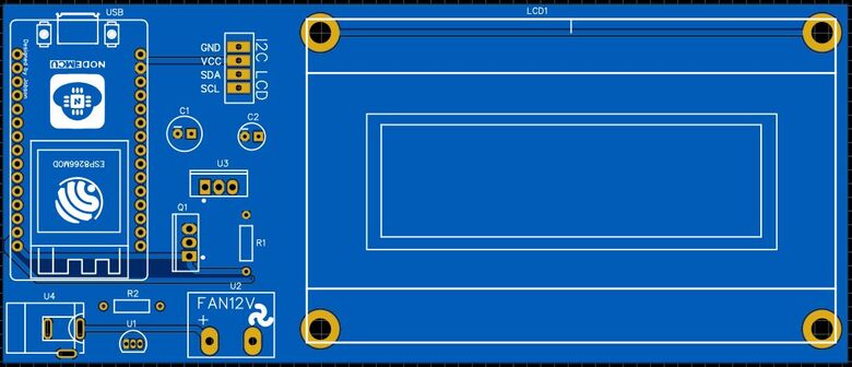
You can assemble the components on the PCB Board.
Blynk 2.0 Web & Mobile Dashboard Setup
Now let’s set up the Blynk Web Dashboard first. To do that visit blynk.io and sign up using the email ID.
First Create a New Template.

Assign the name, Hardware & Connection Type.

From the Web Dashboard, Create 4 widgets Gauge, Label, LED & Slider.

For the Gauge setting, choose the Virtual pin V4. This will be used for displaying the fan speed in percentage.

For temperature display in label, select virtual pin V3 and data type as integer.

For the slider assign the virtual pin as V7. The slider is used to set up the threshold value at which the fan would turn on.

For LED setting rename the variable as Fan as this will indicate the fan ON/OFF status. The virtual pin assigned for the fan is V0.

Apart from the Web Dashboard, you can also set up your Mobile App Dashboard. For that download the Blynk from Playstore or AppStore. Using the Mobile dashboard, you can have the same observation as the web dashboard.
Source Code/Program
The code for IoT Temperature Based Fan Speed Control & Monitoring System using ESP8266 is written in Arduino IDE. We need to install the following library first.
- Blynk Library: Download
- OneWire Library: Download
- Dallas Temperature Library: Download
- I2C LCD Library: Download
From the following lines you can change the WiFi SSID, Password & Blynk Authentication Token.
|
1 2 3 |
char auth[] = "*********************"; //Blynk Authntication Token char ssid[] = "*********************"; //WiFi SSID char pass[] = "*********************"; //WiFi Password |
From the Board List select NodeMCU 1.0 Board and from the COM Port list, select the right port for ESP8266. Then hit the upload button to upload the code.
|
1 2 3 4 5 6 7 8 9 10 11 12 13 14 15 16 17 18 19 20 21 22 23 24 25 26 27 28 29 30 31 32 33 34 35 36 37 38 39 40 41 42 43 44 45 46 47 48 49 50 51 52 53 54 55 56 57 58 59 60 61 62 63 64 65 66 67 68 69 70 71 72 73 74 75 76 77 78 79 80 81 82 83 84 85 86 87 88 89 90 91 92 93 94 95 96 97 98 99 100 101 102 103 104 |
#include <ESP8266WiFi.h> #include <BlynkSimpleEsp8266.h> #include <OneWire.h> #include <DallasTemperature.h> #include <LiquidCrystal_I2C.h> LiquidCrystal_I2C lcd(0x27, 16, 2); #define BLYNK_PRINT Serial #define ONE_WIRE_BUS 12 int fanPin = 16; int dutyCycle = 0; float temp = 0; int threshold = 30; OneWire oneWire(ONE_WIRE_BUS); DallasTemperature sensors(&oneWire); WidgetLED FAN(V0); char auth[] = "*********************"; char ssid[] = "*********************"; char pass[] = "*********************"; void setup() { Serial.begin(115200); sensors.begin(); pinMode(fanPin, OUTPUT); lcd.init(); lcd.backlight(); lcd.setCursor(0, 0); lcd.print(" Temperature "); lcd.setCursor(0, 1); lcd.print("Monitoring System"); delay(4000); lcd.clear(); analogWriteRange(100); analogWriteFreq(10000); Blynk.begin(auth, ssid, pass, "blynk.cloud", 80); } BLYNK_WRITE(V7) { threshold = param.asInt(); Serial.print(" The Threshhold thresholdue is: "); Serial.println(threshold); Serial.println(); } void controlFanSpeed(int fanSpeedPercent) { analogWrite(fanPin, fanSpeedPercent); Serial.print("Fan Speed: "); Serial.print(fanSpeedPercent); Serial.println("%"); lcd.setCursor(0, 1); lcd.print("Fan Speed: "); lcd.print(fanSpeedPercent); lcd.print("%"); } void loop() { Blynk.run(); sensors.requestTemperatures(); temp = sensors.getTempCByIndex(0); Serial.print("Temperature: "); Serial.print(temp); Serial.println("*C"); lcd.setCursor(0, 0); lcd.print("Temp: "); lcd.print(temp); lcd.print("*C"); Blynk.virtualWrite(V3, temp); if (temp >= threshold) { FAN.on(); int fanSpeedPercent = map(temp, threshold, 55, 10, 100); controlFanSpeed(fanSpeedPercent); Blynk.virtualWrite(V4, fanSpeedPercent); } else if (temp < threshold) { FAN.off(); int fanSpeedPercent = 0; controlFanSpeed(fanSpeedPercent); Blynk.virtualWrite(V4, fanSpeedPercent); } } |
For generating PWM we have used the “analogWrite(pin, PWM value)” function in 8 bits. Mean if the PWM value is equivalent to an analog value. So if we need to generate 20% of the duty cycle then we pass 255/5 value as PWM in the “analogWrite” Function.
Testing: IoT Temperature Based Fan Speed Control System
After uploading the code, the ESP8266 will try connecting to the WiFi Network. After it gets connected to the WiFi Network, it connects to the Blynk platform using the Blynk Authentication Token.
At the same time the 16×2 LCD Display will show the temperature in degrees Celsius and Fan Speed in Percentage.

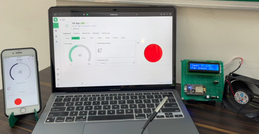
At the same time the Blynk App will also display the Temperature in °C and Fan Speed in the Gauge widget. It will also indicate the Fan ON/OFF status and threshold value in the slider.
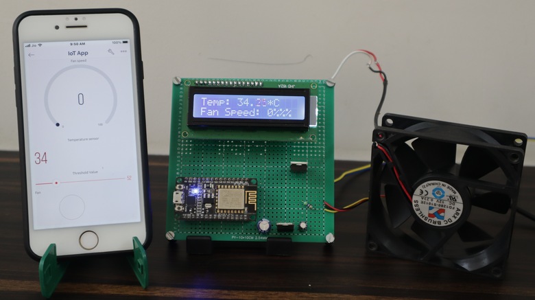
By default the threshold is set to 30°C. It means if the temperature exceeds the threshold value the fan will start automatically. The speed of the fan will gradually increase from 0-100% between the range of threshold value and upper limit. In this case, the upper limit is set to 55°C. In case the current temperature is less than the threshold the fan will not start.
The threshold value can be set using the Blynk Slider.
When the sensor detects a high temperature, the Fan turns on and its speed depends upon the temperature.

The greater the temperature the greater the Fan speed. At a temperature of 55°C, the fan speed becomes 100%. You can change the value of the upper limit of temperature in the code part.

The same thing can be monitored online on Blynk Web Dashboard as well. You can observe the fan speed and temperature from any part of the world.
This is how you can build and setup the IoT Temperature Based Fan Speed Control & Monitoring using ESP8266 and the Blynk Application.
Video Tutorial & Guide


3 Comments
Nice sir
Excellent project. I am planning a similar project using a relay to control the fan operation to cool my stereo cabinet. Using a mosfet is a more elegant solution and I plan to do this once I prove a fan will solve the problem with my Roku box overheating.
However, in your source code for Blynk you should keep the void loop clean. I would suggest using a timer to read the temperature, print to the LCD, adjust the fan, etc every, say, second. Writing data to Blynk in a void loop (which would be thousands of times per second) is going to overload the Blynk server, resulting in communication troubles with the Blynk server.
You probably won’t have any trouble since you are only writing two data points to the server, but you never know. The Blynk community website harps about this all of the time.
I want to design my own PCB. But i cant find the LCD Display and the NodeMCU that you have used. Can you tell me the Part-Numbers?