

Wireless Gesture Controlled Robot Using Accelerometer & Arduino
In this project, we will learn how to make Wireless Gesture Controlled Robot Using Accelerometer & Arduino. Hand Gesture Controlled Robot Application are numerous. It is something similar to autonomous Robot Projects. Here we are going to control a robot wirelessly using hand gestures. This is an easy, user-friendly way to interact with robotic arms too. An accelerometer ADX335 which can detect x-axis & y-axis tilting movements is used for controlling the forward, backward, left, and right directional movements. Even some gesture controlled robot kits are available in the market but what about making it by ourselves.
We are using an ATmega328 microcontroller as the brain of this project. An encoder IC HT12E & a Decoder IC HT12D is used for encoding and decoding of the different wireless signals. Similarly 433 Mhz RF Module is used wireless transmission & receiving of the signal.
Previously we made some other robotic Project. You can check a few of them below:
1. Wireless Bluetooth Controlled Robot using Arduino
2. Wireless Voice Controlled Robot Car Using Arduino
3. WiFi Controlled Robot using ESP8266
4. Make an Automatic Grass Cutting Robot using Arduino
Robots & Human-Machine Interaction
Recently, strong efforts have been carried out to develop intelligent and natural interfaces between users and computer-based systems based on human gestures. Gestures provide an intuitive interface to both humans and computers. Thus, such <ahref=”https://how2electronics.com/gesture-recognition-application-machine-learning/”>Gesture Based Interfaces can not only substitute the common interface devices but can also be exploited to extend their functionality.
What is Robot?
A robot is usually an electro-mechanical machine that can perform tasks automatically. Some robots require some degree of guidance, which may be done using a remote control or with a computer interface. Robots can be autonomous, semi-autonomous, or remotely controlled. Robots have evolved so much and are capable of mimicking humans that they seem to have a mind of their own.
What is Human-Machine Interaction?
An important aspect of a successful robotic system is Human-Machine interaction. In the early years, the only way to communicate with a robot was to program which required extensive hard work. With the development in science and robotics, gesture-based recognition came to life. Gestures originate from any bodily motion or state but commonly originate from the face or hand. Gesture recognition can be considered as a way for a computer to understand human body language. This has minimized the need for text interfaces and GUIs (Graphical User Interface). Read about: Gesture Controlled Mouse.
What is Gesture?

A gesture is an action that has to be seen by someone else and has to convey some piece of information. The gesture is usually considered as a movement of part of the body, esp. a hand or the head, to express an idea or meaning.
Components Required
The following are the lists of components required for making Wireless Gesture Controlled Robot. All the components can be purchased from Amazon.
- 7805 5V Voltage Regulator IC
- ATmega328 Microcontroller
- LM1117-33 3.3V Voltage Regulator IC
- HT12E Encoder IC
- HT12D Decoder IC
- L293D Dual H-Bridge Motor Driver IC
- 433 Mhz Transmitter/Receiver Module
- 200 RPM Motors – 2
- ADXL335 3 Axis Accelerometer
- 17 cm Single Strand Wire Antenna – 2
- 9V Battery
- 9V Battery Connector
- 4.5V, 1.5Ah Lead-Acid battery
- 5 or 6 Pin Female Connector for Accelerometer
- 2 Pins Connector for Battery – 2
- 16 Mhz Crystal Oscillator
- LED 5 mm – 4
- 22pF Ceramic Capacitor – 2
- 0.1µF Ceramic Capacitor
- 0.33µF Ceramic Capacitor
- 10µF, 16V Electrolytic Capacitor
- 1M Resistor
- 1OK Resistor
- 680K Resistor
- 47K Resistor
- 220-ohm Resistor – 4
- Robot Chasis & Wheels
- Jumper Wires
Block Diagram
Our gesture controlled robot works on the principle of accelerometer which records hand movements and sends that data to the comparator which assigns proper voltage levels to the recorded movements. That information is then transferred to an encoder which makes it ready for RF transmission.

On the receiving end, the information is received wirelessly via RF, decoded and then passed onto the microcontroller which takes various decisions based on the received information. These decisions are passed to the motor driver ic which triggers the motors in different configurations to make the robot move in a specific direction. The above block diagram helps to understand the working of the robot.
Circuit Diagram & Description
The RF modules work on the frequency of 433 MHz. You can check this post to learn how RF Module Works- How 433 MHz RF Module Works & Interfacing with Arduino. It means that the carrier frequency of the RF module is 433 MHz. The RF module enables the user to control the robot wirelessly and with ease. The schematic of transmitting end can be seen below:

This transmitted signal is received by the RF receiver, demodulated and then passed onto the decoder IC. The decoder IC decodes the coded waveform and the original data bits are recovered. The input is a serial coded modulated waveform while the output is parallel. The pin 17 of the decoder IC is the Valid Transmission (VT) pin. A led can be connected to this pin which will indicate the status of the transmission. In the case of a successful transmission, the led will blink.
The parallel data from the encoder is fed to the port 1of the microcontroller. This data is in the form of bits. The microcontroller reads these bits and takes decisions on the basis of these bits. What the microcontroller does is, it compares the input bits with the coded bits which are burnt into the program memory of the microcontroller and outputs on the basis of these bits. Port 2 of the microcontroller is used as the output port. Output bits from this port are forwarded to the motor driver IC which drives the motors in a special configuration based on the hand movements.

At a dead stop, a motor produces no voltage. If a voltage is applied and the motor begins to spin, it will act as a generator that will produce a voltage that opposes the external voltage applied to it. This is called Counter Electromotive Force (CEF) or Back Electromotive Force (Back EMF). If a load stops the motors from moving then the current may be high enough to burn out the motor coil windings.
PCB & Gerber Files
The PCB files for both the transmitter and receiver section is given below.

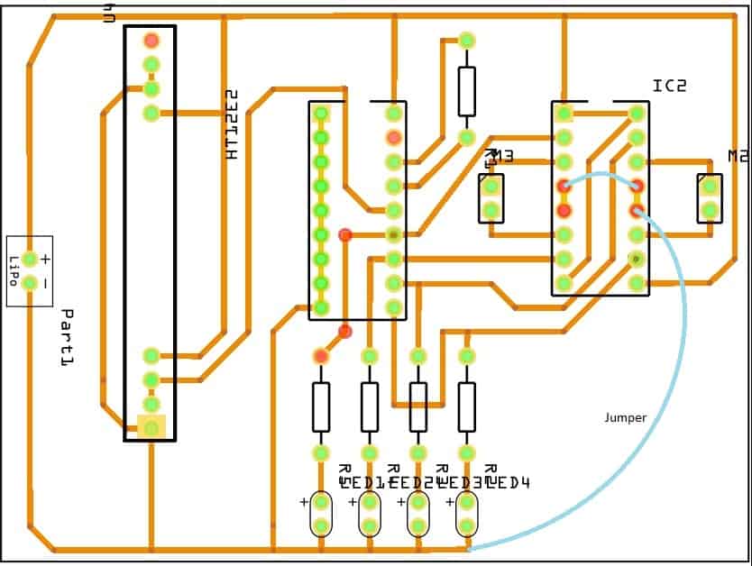
These PCB files can be converted to the Gerber file. So once the Gerber file is ready, you can order the PCB from
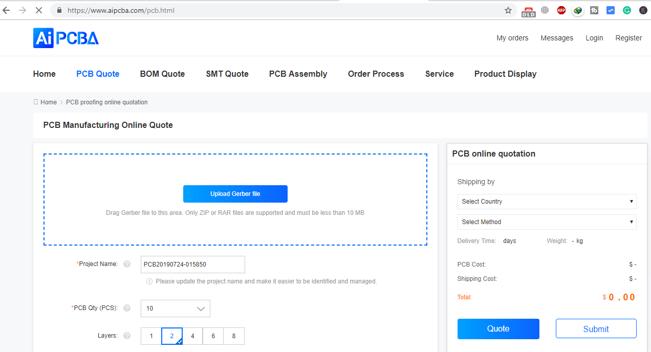
https://www.aipcba.com/. “AiPCBA” is a PCB/PCB Assembly rapid prototyping service company. The services include PCB board supply, PCB assembly, electronic component procurement, and SMT assembly. AiPCBA focuses on HDI, FPC, FPCA, and the combination of small and medium-sized batches and prototypes in soft and hard PCBs.
All you have to do is download the Gerber file from below and upload it to this site and place the order. You will get the good quality PCB within a week at a very cheap price.
Download the Gerber file from below:
1. Transmitter Section PCB Gerber File
2. Receiver Section PCB Gerber File
Making the Hardware Part
Once you order the PCB it will take almost a week or more for delivery. I received the PCB and the PCB quality is really very good
So below are some pictures while making and assembling of the project


Source Code/program
Below is the code for designing Wireless Gesture Controlled Robot Using Accelerometer & Arduino. Simply copy the code and upload it to the Arduino UNO Board. Once the code is uploaded remove the ATmega328 microcontroller from the Arduino UNO board and insert it into the PCB as shown above.
|
1 2 3 4 5 6 7 8 9 10 11 12 13 14 15 16 17 18 19 20 21 22 23 24 25 26 27 28 29 30 31 32 33 34 35 36 37 38 39 40 41 42 43 44 45 46 47 48 49 50 51 52 53 54 55 56 57 58 59 60 61 62 63 64 65 66 67 68 69 70 71 72 73 74 75 76 77 78 79 |
const int ap1 = A0; const int ap2 = A1; int sv1 = 0; int ov1 = 0; int sv2 = 0; int ov2= 0; void setup() { // initialize serial communications at 9600 bps: Serial.begin(9600); pinMode(13,OUTPUT); pinMode(12,OUTPUT); pinMode(11,OUTPUT); pinMode(10,OUTPUT); } void loop() { analogReference(EXTERNAL); //connect 3.3v to AREF // read the analog in value: sv1 = analogRead(ap1); ov1 = map(sv1, 0, 1023, 0, 255); delay(2); sv2 = analogRead(ap2); ov2 = map(sv2, 0, 1023, 0, 255); delay(2); Serial.print("Xsensor1 = " ); Serial.print(sv1); Serial.print("\t output1 = "); Serial.println(ov1); Serial.print("Ysensor2 = " ); Serial.print(sv2); Serial.print("\t output2 = "); Serial.println(ov2); if(analogRead(ap1)<514 &&analogRead (ap2)<463) // for backward movement { digitalWrite(13,HIGH); digitalWrite(12,LOW); digitalWrite(11,HIGH); digitalWrite(10,LOW); } else { if(analogRead(ap1)<486 &&analogRead (ap2)>508) // for left turn { digitalWrite(13,LOW); digitalWrite(12,HIGH); digitalWrite(11,HIGH); digitalWrite(10,LOW); } else { if(analogRead(ap1)>512 &&analogRead (ap2)>560) // for forward { digitalWrite(13,LOW); digitalWrite(12,HIGH); digitalWrite(11,LOW); digitalWrite(10,HIGH); } else { if(analogRead(ap1)>550 &&analogRead (ap2)>512)//for right turn { digitalWrite(13,HIGH); digitalWrite(12,LOW); digitalWrite(11,LOW); digitalWrite(10,HIGH); } else { digitalWrite(13,HIGH); digitalWrite(12,HIGH); digitalWrite(11,HIGH); digitalWrite(10,HIGH); } } } } } |
Working of the Project
The accelerometer records the hand movements in the X and Y directions only and outputs constant analog voltage levels. These voltages are fed to the microcontroller and encoder IC which compares it with the reference voltages that we have set via variable resistors attached to the IC. The levels that we have set are 1.7V and 1.4V. Every voltage generated by the accelerometer is compared with these and an analog 1 or 0 signal is given out by the IC.
This analog signal is the input to the encoder IC. The input to the encoder is parallel while the output is a serial coded waveform that is suitable for RF transmission. A push-button is attached to pin 14 of this IC which is the Transmission Enable (TE) pin. The coded data will be passed onto the RF module only when the button is pressed. This button makes sure no data is transmitted unless we want.
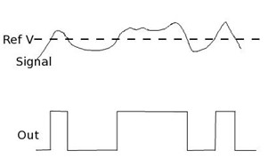
The RF transmitter modulates the input signal using Amplitude Shift Keying (ASK) modulation. It is the form of modulation that represents digital data as variations in the amplitude of a carrier wave.
The following figure shows the modulated output of the RF module:

Video Tutorial & Explanation
Follow the video tutorial for making Gesture Controlled Robot Arduino using Accelerometer & Arduino.


")


