

Here is a simple circuit for Temperature to Voltage Converter using Thermistor & 741 Op-Amp IC. This Circuit will operate in a temperature range of 0 to 24 degrees Celsius (32 to 75 degrees Fahrenheit). The output rate of conversion is 500mV per degree Celsius. The output can be easily read by any normal voltmeter.
Overview
With this simple Temperature to Voltage Converter using Thermistor & 741 circuits, you can do a precise measurement of the room temperature. The circuit operates at 6V Power Supply. An NTC (Negative Temperature Coefficient) thermistor or Temperature Variable resistor is used as a sensor that has a strong temperature dependence. In this circuit, if the Thermistor detects temperature rise then the output voltage rises with 0.5 V per 1 degree Celcius.
The temperature to voltage conversion factor depends on the type of thermistor resistance used. If you want to read the temperature directly on a universal measurement device then the value of feedback resistor R17 680K must be chosen so that the desired sensitivity is achieved.
While if you want to measure the temperature you can go for the LM35 Temperature Sensor. Read more about it here: Digital Thermometer using LM35 Temperature Sensor
Components Required
Following are the components required for designing Circuit for Temperature to Voltage Converter .
- 741 Op-Amp IC
- Resistor 10K – 4
- Resistor 100K – 2
- Resistor 680K – 1
- Potentiometer 10K
- Thermistor 10K
- Capacitor 0.1uF
- 6V Power Supply
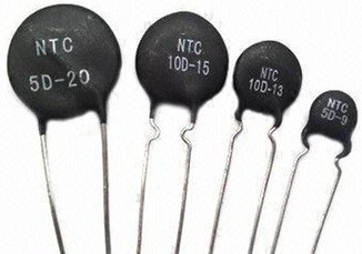
What is Thermistor & How do they Work ?
Thermistors are thermally sensitive resistors whose prime function is to exhibit a large, predictable and precise change in electrical resistance when subjected to a corresponding change in body temperature.
Negative Temperature Coefficient (NTC) thermistors exhibit a decrease in electrical resistance when subjected to an increase in body temperature and Positive Temperature Coefficient (PTC) thermistors exhibit an increase in electrical resistance when subjected to an increase in body temperature. Because of their very predictable characteristics and their excellent long term stability, thermistors are generally accepted to be the most advantageous sensor for many applications including temperature measurement and control.
The most important characteristic of a thermistor is its extremely high-temperature coefficient of resistance. Modern thermistor technology results in the production of devices with extremely precise resistance versus temperature characteristics, making them the most advantageous sensor for a wide variety of applications.
Temperature to Voltage Converter Circuit using Thermistor & 741
Here is a tested circuit diagram for Temperature to Voltage Converter Project. You can either assemble the circuit on a breadboard or you can simply make a PCB for it.

The 741 Op-Amp IC is used as the difference amplifier. There are inputs as bridge circuit includes with R11 to TH1, by at R11, R12, R13 and PR1 are constant arms of the bridge. The thermistor TH1 is an arm of Bridget’s changing values.
The voltage between R11 and R12 has about 3.4V at zero degrees Celsius. The PR1 is calibrated to the output of the op-amp is 0V. There are conditions of the NTC, the NTC resistance at higher temperatures is decreased, and the voltage drop across NTC is reduced. Making the output of the Op-amp with higher voltage. The NTC is a normal thermistor that resistance 10K but you can change the value of R13 and PR1 to be proportional.


