

This post is all about RGB LED Strip Color Control with Bluetooth & Arduino to see different mixed color of LED. The LEDs light strip can be controlled wirelessly via Android App. With the received data, we decide which color of the RGB strip to activate.
Overview
In this tutorial, we are going to learn about how to connect a 12v RGB LED Strip with Arduino and how to program Arduino Board with RGB LED Strip to control various colour wirelessly through Bluetooth via Android App. This RGB Multi-Color LED Strip is Dimmable and can be used to make many DIY LED Projects.
This Strip is a perfect choice for indoor or outdoor decoration on Diwali, Christmas, Parties, Marriage or on other events. Light will change colours and speed automatically and periodically on your choice. It has not only RGB (Red, Green, Blue) but a 16 multicoloured Light changer. You can have the DIY selection to create your great led mood lighting.
See the previous post: Interfacing RGB LED Strip with Arduino with Fade & Color Effect
Bill of Materials
Following are the components required to make this project. All the components can be easily purchased from Amazon. The purchased links are given below:
| S.N. | Components | Quantity | Purchase Links |
|---|---|---|---|
| 1 | Arduino UNO Board | 1 | Amazon | AliExpress |
| 2 | 12V RGB LED Strip | 1 | Amazon | AliExpress |
| 3 | HC-05 Bluetooth Module | 1 | Amazon | AliExpress |
| 4 | MOSFET IRF540N | 3 | Amazon | AliExpress |
| 5 | 12V Power Supply | 1 | Amazon | AliExpress |
| 6 | Connecting Wires | 20 | Amazon | AliExpress |
| 7 | Breadboard | 1 | Amazon | AliExpress |
12V RGB LED Strip

The SMD5050 type 12V RGB LED Strip is very popular in market. It operates at 12V, 1.5A DC Power Supply. It can generate colours like RGB, White, Warm White, Red, Green, Blue, Yellow etc. There are a total of 60 LEDs per piece.

The RGB LED Strip has SMD5050 which has 3 samll sized LED of red , green & blue colour. All the 3 LED has 3 resistors attached to it to prevent the LED from getting damaged due to over voltage.

It has cutting marks after each 3 SMD5050 and is detachable. It has a 3M double-sided adhesive and at the back, it has double-sided copper conductive PCB with a great heat dissipation.

It has 4 wires. The first one is white which is the positive 12V input. The other 3 wires are the red, green and blue signal wires. In order to create a broad variety of colors we should give more or less brightness to each of this 3 basic colors. To do that we shoould apply a PWM signal to this color pins. If the white pin is already connected to a positive 12V votage, in order to close the circuit, the RGB output pins should be modulated toward ground.
Current/Power Requirements for RGB LED Strip
The problem with the Arduinois that its digital outputs can supply more than 200mA and this strip at full brightness could draw more than 1A. For that we have to put something between the Arduino PWM signal and the LED strip. To do this we have two options, either to use high power BJT or to go with MOSFET.
I tested the current consumption by RGB LED Strip at different conditions. When its glowing to full brightness, the current goes more than 1A. So it is advised to use an adpater of 12V, 1.5A or higher current rating.

Circuit for RGB LED Strip Color Control with Bluetooth & Arduino
Now let us learn about interfacing SMD5050 LED Strip with Bluetooth & Arduino. For each colour line, we need 1 MOSFET and they need to be rated to handle the max current. It’s about 330mA per meter for each channel, 1.66 A per channel for a 5-meter strip.
I have used an IRF540N N Channel MOSFET. You can use any NPN transistors like TIP120, TIP121, TIP122 of N-Channel MOSFETs like IRF2807, IRF 530, IRFZ44N based on your application you can change the transistors. The difference between these transistors is that they have a different collector-emitter current rating. For example, if you are using a large length of RGB LED strip then to drive them you will be needing high current transistors like IRF540 which have Drain Current (Id): 28 Amps.

First connect HC-05/HC-06 Bluetooth Module to Arduino. Connect its VCC to 5V and GND to GND. Also connect its TX pin to Rx o Arduino and RX to TX of Arduino. The TX/RX Pins are 3.3V tolerable, so if you are going to use this setup for long you need to make a voltage divider network for controlling.
Connect the IRF540N MOSFET and RGB LED Strip as shown in the Circuit Diagram above. Connect the 1st Pin of IRF540N which is a GATE pin to Arduino PWM Pin as D6, D5, D3 respectively for RGB pin. The 2nd pin of IRF540N MOSFET which is a Drain Pin is connected to RGB LED Pins. And the Source Pin of IRF540N which is the 3rd pin is connected to GND. The IRF540n is working as a switch here. You need to supply 12V DC from external power supply like DC Adapter or 12V Transformer rectifier Circuit.

Source Code/Program
The Source Code for Interfacing RGB LED Strip with Arduino with Fade & Rolling Color Effect is given below. There is no need of any library for this. You can simply upload the code to the Arduino board. Remember, while uploading the code to the Arduino, disconnect this TX/RX pins otherwise the code won’t upload and an error would pop up.
|
1 2 3 4 5 6 7 8 9 10 11 12 13 14 15 16 17 18 19 20 21 22 23 24 25 26 27 28 29 30 31 32 33 34 35 36 37 38 39 40 41 42 43 44 45 46 47 48 49 50 51 52 53 54 55 56 57 58 59 60 61 62 63 64 65 66 67 68 69 70 71 72 73 74 75 76 77 78 79 80 81 82 83 84 85 86 87 88 89 90 91 92 93 94 95 96 97 98 |
int color=0; //define the RGB pind int red = 6; int green = 5; int blue = 7; char received; void setup() { Serial.begin(9600); //Start the serial comunication for the bluetooth module pinMode(red, OUTPUT); //Red color pwm pin defined as output pinMode(green, OUTPUT); //Green color pwm pin defined as output pinMode(blue, OUTPUT); //Blue color pwm pin defined as output //Give first value of the PWM 0, we start with the RGB LEDs off analogWrite(red,0); analogWrite(green,0); analogWrite(blue,0); } void loop() { if(Serial.available()>0){ // read the bluetoot data and store it color = Serial.read(); char Rec = char(color); if (Rec != '0') { Serial.println(Rec); //This is to visualise the received character on the serial monitor } } //LEDs off if (color == 'n') { analogWrite(red,0); analogWrite(green,0); analogWrite(blue,0); } //White if (color == 'w') { analogWrite(red,255); analogWrite(green,255); analogWrite(blue,255); } //Red if (color == 'r') { analogWrite(red,255); analogWrite(green,0); analogWrite(blue,0); } //Green if (color == 'g') { analogWrite(red,0); analogWrite(green,255); analogWrite(blue,0); } //Blue if (color == 'b') { analogWrite(red,0); analogWrite(green,0); analogWrite(blue,255); } //Orange if (color == 'o') { analogWrite(red,255); analogWrite(green,153); analogWrite(blue,0); } //Violet if (color == 'v') { analogWrite(red,102); analogWrite(green,0); analogWrite(blue,153); } //Cyan if (color == 'c') { analogWrite(red,0); analogWrite(green,255); analogWrite(blue,255); } //Yellow if (color == 'y') { analogWrite(red,255); analogWrite(green,204); analogWrite(blue,0); } } |
RGB LED Strip Control Android App
The LED color can be controlled wirelessly via bluetooth using the Android App given below. The Android App is designed using MIT App Inventor.
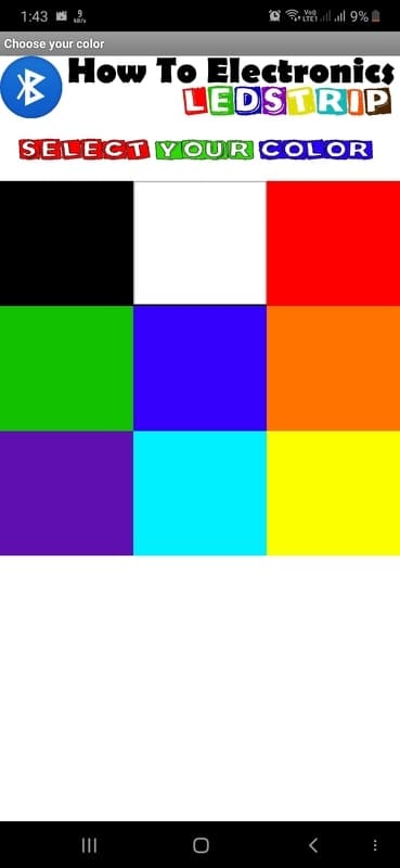
Download the android app from the below link and install it on your smartphone. Before we start the App we have to synchronize the device. Open the Bluetooth settings on your smartphone. Search for devices and select the HX06 when found. The password should be 1234 or 0000. Now we are synchronized. Open the App, click the Bluetooth icon, and select the HC06 device from that list. Now just select your color and observe the magic.
Results
Once the code is uploaded and 12V supply is turned on you will need Android App to control the LED Color. Some of the LED fading pictures are given below and for full demonstration go through the video below.


")


