

Overview
In this project, we will learn how to make our own Dissolved Oxygen Meter using DfRobot Analog Dissolved Oxygen Sensor & Arduino. Dissolved oxygen refers to the extent of free, non-compound oxygen present in water or other liquids. it’s one of the foremost important parameters when assessing water quality due to its influence on the organisms living within a body of water. A DO level that’s too high or too low can harm aquatic life and affect water quality.
Since measuring the parameter of water quality is a complex task, so measuring the dissolved oxygen in water is also not an easy task. That is why the Dissolved Oxygen Meter (DO Meter) available in the market is very expensive. That is why it is important to make your own Dissolved Oxygen Meter. So the Gravity Analog Dissolved Oxygen Sensor from DfRobot is one of the most popular and best Dissolved Oxygen Sensors that are available in the market. The Analog dissolved oxygen sensor kit from DfRobot is compatible with Arduino, ESP8266, ESP32, STM32 microcontrollers & Raspberry Pie. The product is used to measure the dissolved oxygen in water, to reflect the water quality. It is widely applied in many water quality applications, such as aquaculture, environment monitoring, natural science, etc.

In this project, we will interface Gravity Analog Dissolved Oxygen Sensor with Arduino Board and 0.96″ OLED Display. We will first prepare the DO Sensor by filling the 0.5N Sodium Hydroxide Solution. Then we will prepare the sensor for testing. Once the sensor is prepared, we will go through the Arduino Dissolved Oxygen Sensor calibration code & we will calibrate the sensor. And then finally we will make our own Dissolved Oxygen Meter & display the dissolved Oxygen value in OLED Display.
Bill of Materials
All the components that you need for the project is listed below. You can buy all the components from Amazon using the given purchase below.
| S.N. | Components Name | Quantity | Purchase Links |
|---|---|---|---|
| 1 | Arduino Nano Board | 1 | Amazon | AliExpress |
| 2 | Gravity Dissolved Oxygen Sensor | 1 | Amazon | AliExpress |
| 3 | 0.96" I2C OLED Display | 1 | Amazon | AliExpress |
| 4 | Connecting Wires | 10 | Amazon | AliExpress |
| 5 | Breadboard | 1 | Amazon | AliExpress |
Apart from these electronics items you might need the filling solution, i.e 0.5N Sodium Hydroxide Solution & some measuring flask for measuring the volume of liquid.
Dissolved Oxygen in Water
What is Dissolved Oxygen?
Dissolved oxygen refers to the level of free, non-compound oxygen present in water or any other liquids. The non-compound oxygen, or free oxygen (O2), is oxygen that’s not bonded to any other element. Dissolved oxygen is the presence of the free O2 molecules within the water. The bonded oxygen molecule in water (H2O) is in a compound and does not count toward DO levels. One can imagine that free oxygen molecules dissolve in water much the same way salt or sugar does when it’s stirred.

Dissolved oxygen enters the water through the air or as a plant byproduct of photosynthesis. From the air, oxygen can slowly diffuse across the water’s surface from the surrounding atmosphere, or be mixed in quickly through aeration. Dissolved oxygen is also produced as a waste product of photosynthesis from phytoplankton, algae, seaweed, and other aquatic plants.

Dissolved oxygen levels may be affected by a variety of natural factors, some of which include:
1. Aquatic life (more aquatic life = less DO)
2. Decomposition levels (decomposition processes consume oxygen, resulting in less DO)
3. Body of water type (running streams dissolve more oxygen than still water)
4. Altitude (high altitude = less DO)
What is Dissolved Oxygen Meter?
The Dissolved Oxygen Meter (DO meter) measures the amount of oxygen dissolved in an aqueous solution. The dissolved oxygen meter is of 3 different types & made using the following sensors.
1. Galvanic dissolved oxygen sensors
2. Polarographic dissolved oxygen sensors
3. Optical dissolved oxygen sensors
Dissolved Oxygen Calculation
DO can be expressed as a concentration per unit volume, or as a percentage. In aquatic environments, oxygen saturation is a ratio of the concentration of dissolved oxygen (O2), to the maximum amount of oxygen that will dissolve in that water body, at the temperature and pressure which constitute stable equilibrium conditions.
Dissolved oxygen concentration levels may be expressed as milligrams per liter (mg/L) or parts per million (ppm). 1 mg/L is equal to 1 ppm. Dissolved oxygen saturation is expressed as a percentage.
Gravity Analog Dissolved Oxygen Sensor
Sensor Overview

This is a Gravity Analog Dissolved Oxygen sensor kit from DfRobot which can be easily interfaced with Arduino & any other microcontrollers. The sensor is used to measure the dissolved oxygen in the water so that the water quality can be known. It is widely applied in many water quality applications, such as aquaculture, Fishery, environment monitoring, natural science, and laboratory applications.

The DfRobot Dissolved Oxygen Sensor has a Galvanic type probe. The galvanic type probe does not need polarization time, and stay available at any time. The working mechanism of the Galvanic type Dissolved Oxygen sensor is explained below.

The signal converted board has a BNC connector which can directly be connected to Galvanic Probe. The Signal converter boards basically amplify the minor voltage difference to a readable signal that can be detected by Arduino. The signal converter board is plug and play and has good compatibility.

The sensor tip is covered by a membrane cap where a solution is filled. The oxygen-permeable membrane in the membrane cap is sensitive and fragile. Use caution when handling it. Fingernails and other sharp objects should be avoided. It can be easily integrated into any control or detecting system.
Sensor Features & Specifications
- Working Voltage: 3.3~5.5V
- Output Voltage: Analog 0~3.0V
- Sensor Type: Galvanic Probe
- Detection Range: 0~20mg/L
- Response Time: Up to 98% full response, within 90 seconds (25℃)
If you want to learn more about the specification feature & life of the sensor, you can visit the manufacturer site here:
Working of Dissolved Oxygen Sensor
Galvanic DO sensors consist of two electrodes: an anode and cathode. Both of these electrodes are immersed in electrolytes (inside the sensor body). An oxygen permeable membrane separates the anode and cathode from the measured water.

The permeable membrane allows oxygen from the sample water to diffuse into the sensor, where it is reduced at the cathode. This chemical reaction produces an electrical signal, which travels from the cathode to the anode and then into the dissolved oxygen measuring instrument. Consumption of oxygen at the cathode creates a pressure difference across the membrane that varies based on the partial pressure of oxygen in the sample. Therefore, as oxygen concentration increases, partial pressure and the rate of diffusion also increase, and the current to the instrument increases proportionally.
Preparing 0.5 mol/L NaOH solution
Before getting the Dissolved Oxygen Sensor probe to work, you need to prepare the probe. For preparing the probe you need to prepare 0.5 mol/L NaOH solution. You need a Sodium Hydroxide(NaOH) Crystals. The NaOH Crystals can be easily available in any Chemistry shop.
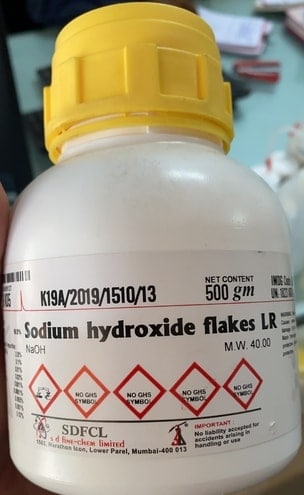
To make 0.5M of NaOH, measure 20g of sodium hydroxide and dissolve it in 1000 ml of water.

While mixing the NaOH Crystal with water, the solution will produce heat because of the chemical reaction. So mix the solution and let is dissolve & cool down up to 30 minutes.
Preparing the Sensor Probe
For a new dissolved oxygen probe, 0.5 mol/L NaOH solution should be added into the membrane cap first as the filling solution. To do that follow the following steps.
Unscrew the membrane cap from the probe and fill about 2/3 volume of the cap with a 0.5 mol/L NaOH solution. Make sure the probe is in a vertical position with respect to the horizontal plane. Carefully screw the cap back to the probe. It would be nice if a little bit of solution overflows out of the cap to ensure the probe is fully filled with NaOH solution.

When screwing the cap back to the probe, the probe should be in a vertical position with respect to the horizontal plane to avoid creating bubbles in the filling solution.
If the cap is fully filled with NaOH solution, there will be too much solution overflowing when screwing the cap back to the probe. If the filling solution is too little, bubbles may be created inside the cap. In sum, the best way is to fill about 2/3 volume of the cap. A little bit of overflow when screwing the cap back to the probe is okay.
Dissolved Oxygen Sensor & Arduino Connection Diagram
Here is a circuit diagram for interfacing dissolved Oxygen Sensor with Arduino Board. First, connect the probe to BNC connector on the signal converter board.

The sensor works at 3.3V to 5V. So, connect its VCC pin to 3.3V of the Arduino Board. Connect the GND to GND. Similarly, connect the output Analog pin to A1 of Arduino Board.
Dissolved Oxygen Sensor Calibration
If you are using the Sensor for the first time or the sensor is used for a long time then you need to calibrate the probe for accuracy.
There are two methods for calibrating the sensor:
- Single-point calibration: only calibrate the saturated dissolved oxygen at a fixed temperature, suitable for use when the temperature is stable
- Two-point calibration: calibrate the saturated dissolved oxygen at different temperatures, you can calculate the temperature compensation, used when the temperature changes
But I prefer the first method, i.e Single-Point Calibration as it is the easiest method.
Dissolved Oxygen Sensor Arduino Calibration Code
Copy the following code and upload it to the Arduino Board.
|
1 2 3 4 5 6 7 8 9 10 11 12 13 14 15 16 17 18 |
#include <Arduino.h> #define VREF 5000//VREF(mv) #define ADC_RES 1024//ADC Resolution uint32_t raw; void setup() { Serial.begin(115200); } void loop() { raw=analogRead(A1); Serial.println("raw:\t"+String(raw)+"\tVoltage(mv)"+String(raw*VREF/ADC_RES)); delay(1000); } |
Now follow the following steps to calibrate the probe:
- Prepare the probe (explained above)
- Wet the probe in pure water and shake off excess water drops
- Expose the probe to the air and maintain proper airflow (do not use a fan to blow)
- After the output voltage is stable, record the voltage, which is the saturated dissolved oxygen voltage at the current temperature
When the reading becomes stable note down the voltage reading. This voltage reading is required in the final code. I have done the calibration at 25 deg Celcius Temperature. So by default 25°C is assigned in the code.

If you want to learn more about the Dissolved Oxygen Sensor Calibration method and follow the other way for calibration, you can follow this article here: DO Sensor Calibration.
When the temperature is fixed, the voltage is linearly related to the dissolved oxygen concentration. Saturated dissolved oxygen is greatly affected by temperature changes. In order to improve accuracy, it is necessary to consider changes in dissolved oxygen and saturation voltage caused by temperature changes. The following table indicates the change in concentration according to temperature.

Final Dissolved Oxygen Sensor Arduino Code
Once the calibration factor is achieved, you can make your own Dissolved Oxygen Meter.

The following code below can be uploaded to Arduino Board to make you own dissolved Oxygen Meter. Change the following line in the code like temperature and calibration voltage. The calibration is done at 25°C and it is preferred to do the calibration at this temperature.
|
1 2 |
#define CAL1_V (131) //mv #define CAL1_T (25) //℃ |
Since, we are following the single-point calibration method, we are defining this line.
|
1 |
#define TWO_POINT_CALIBRATION 0 |
If you are going for two-point calibration then you to define the line as
|
1 |
#define TWO_POINT_CALIBRATION 1 |
Also change the voltage and temperature parameter from these lines if you are going for two-point calibration.
|
1 2 3 4 |
#define CAL1_V (131) //mv #define CAL1_T (25) //℃ #define CAL2_V (1300) //mv #define CAL2_T (15) //℃ |
Here is a complete final code, you can upload it directly to the Arduino board.
|
1 2 3 4 5 6 7 8 9 10 11 12 13 14 15 16 17 18 19 20 21 22 23 24 25 26 27 28 29 30 31 32 33 34 35 36 37 38 39 40 41 42 43 44 45 46 47 48 49 50 51 52 53 54 55 56 57 58 59 60 61 |
#include <Arduino.h> #define DO_PIN A1 #define VREF 5000 //VREF (mv) #define ADC_RES 1024 //ADC Resolution //Single-point calibration Mode=0 //Two-point calibration Mode=1 #define TWO_POINT_CALIBRATION 0 #define READ_TEMP (25) //Current water temperature ℃, Or temperature sensor function //Single point calibration needs to be filled CAL1_V and CAL1_T #define CAL1_V (131) //mv #define CAL1_T (25) //℃ //Two-point calibration needs to be filled CAL2_V and CAL2_T //CAL1 High temperature point, CAL2 Low temperature point #define CAL2_V (1300) //mv #define CAL2_T (15) //℃ const uint16_t DO_Table[41] = { 14460, 14220, 13820, 13440, 13090, 12740, 12420, 12110, 11810, 11530, 11260, 11010, 10770, 10530, 10300, 10080, 9860, 9660, 9460, 9270, 9080, 8900, 8730, 8570, 8410, 8250, 8110, 7960, 7820, 7690, 7560, 7430, 7300, 7180, 7070, 6950, 6840, 6730, 6630, 6530, 6410}; uint8_t Temperaturet; uint16_t ADC_Raw; uint16_t ADC_Voltage; uint16_t DO; int16_t readDO(uint32_t voltage_mv, uint8_t temperature_c) { #if TWO_POINT_CALIBRATION == 00 uint16_t V_saturation = (uint32_t)CAL1_V + (uint32_t)35 * temperature_c - (uint32_t)CAL1_T * 35; return (voltage_mv * DO_Table[temperature_c] / V_saturation); #else uint16_t V_saturation = (int16_t)((int8_t)temperature_c - CAL2_T) * ((uint16_t)CAL1_V - CAL2_V) / ((uint8_t)CAL1_T - CAL2_T) + CAL2_V; return (voltage_mv * DO_Table[temperature_c] / V_saturation); #endif } void setup() { Serial.begin(115200); } void loop() { Temperaturet = (uint8_t)READ_TEMP; ADC_Raw = analogRead(DO_PIN); ADC_Voltage = uint32_t(VREF) * ADC_Raw / ADC_RES; Serial.print("Temperaturet:\t" + String(Temperaturet) + "\t"); Serial.print("ADC RAW:\t" + String(ADC_Raw) + "\t"); Serial.print("ADC Voltage:\t" + String(ADC_Voltage) + "\t"); Serial.println("DO:\t" + String(readDO(ADC_Voltage, Temperaturet)) + "\t"); delay(1000); } |
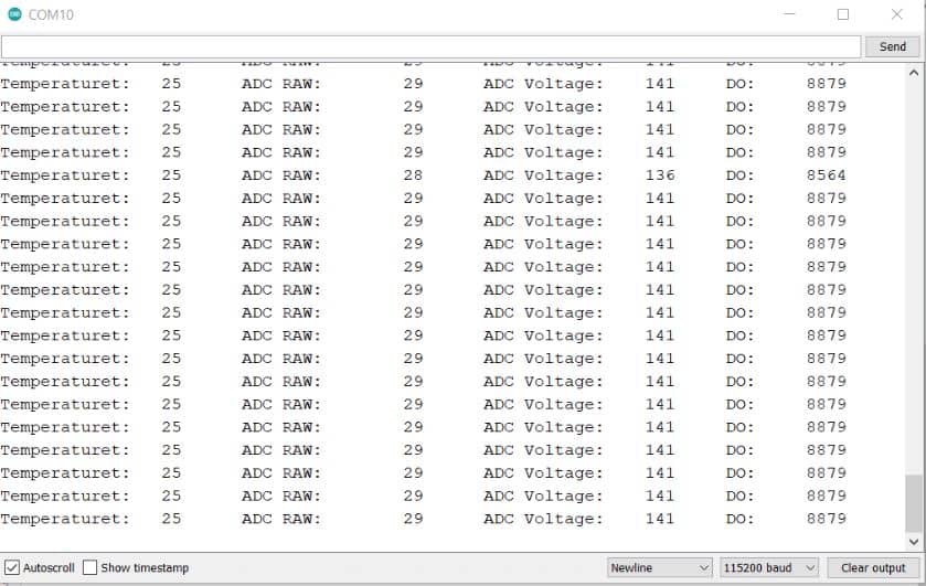
After uploading the code, you can open the Serial Monitor and you will see the following logged value in Serial Monitor.
DIY Dissolved Oxygen Meter
Now if you want to make your own dissolved Oxygen Meter, you can add a display to the Board. The 0.96″ I2C OLED Display is the best display for this application as it has a 4 pin I2C interface and the code is simple. The connection diagram with OLED Display is given below.

Now copy the following code and upload it to the Arduino Board.
|
1 2 3 4 5 6 7 8 9 10 11 12 13 14 15 16 17 18 19 20 21 22 23 24 25 26 27 28 29 30 31 32 33 34 35 36 37 38 39 40 41 42 43 44 45 46 47 48 49 50 51 52 53 54 55 56 57 58 59 60 61 62 63 64 65 66 67 68 69 70 71 72 73 74 75 76 77 78 79 80 81 82 83 84 85 86 87 88 89 |
#include <Arduino.h> #include <SPI.h> #include <Wire.h> #include <Adafruit_GFX.h> #include <Adafruit_SSD1306.h> #define SCREEN_WIDTH 128 // OLED display width, in pixels #define SCREEN_HEIGHT 64 // OLED display height, in pixels #define OLED_RESET -1 // Reset pin # (or -1 if sharing Arduino reset pin) Adafruit_SSD1306 display(SCREEN_WIDTH, SCREEN_HEIGHT, &Wire, OLED_RESET); #define DO_PIN A1 #define VREF 5000 //VREF (mv) #define ADC_RES 1024 //ADC Resolution //Single-point calibration Mode=0 //Two-point calibration Mode=1 #define TWO_POINT_CALIBRATION 0 #define READ_TEMP (25) //Current water temperature ℃, Or temperature sensor function //Single point calibration needs to be filled CAL1_V and CAL1_T #define CAL1_V (131) //mv #define CAL1_T (25) //℃ //Two-point calibration needs to be filled CAL2_V and CAL2_T //CAL1 High temperature point, CAL2 Low temperature point #define CAL2_V (1300) //mv #define CAL2_T (15) //℃ const uint16_t DO_Table[41] = { 14460, 14220, 13820, 13440, 13090, 12740, 12420, 12110, 11810, 11530, 11260, 11010, 10770, 10530, 10300, 10080, 9860, 9660, 9460, 9270, 9080, 8900, 8730, 8570, 8410, 8250, 8110, 7960, 7820, 7690, 7560, 7430, 7300, 7180, 7070, 6950, 6840, 6730, 6630, 6530, 6410 }; uint8_t Temperaturet; uint16_t ADC_Raw; uint16_t ADC_Voltage; uint16_t DO; int16_t readDO(uint32_t voltage_mv, uint8_t temperature_c) { #if TWO_POINT_CALIBRATION == 00 uint16_t V_saturation = (uint32_t)CAL1_V + (uint32_t)35 * temperature_c - (uint32_t)CAL1_T * 35; return (voltage_mv * DO_Table[temperature_c] / V_saturation); #else uint16_t V_saturation = (int16_t)((int8_t)temperature_c - CAL2_T) * ((uint16_t)CAL1_V - CAL2_V) / ((uint8_t)CAL1_T - CAL2_T) + CAL2_V; return (voltage_mv * DO_Table[temperature_c] / V_saturation); #endif } void setup() { Serial.begin(115200); display.begin(SSD1306_SWITCHCAPVCC, 0x3C); //initialize with the I2C addr 0x3C (128x64) display.clearDisplay(); delay(10); } void loop() { Temperaturet = (uint8_t)READ_TEMP; ADC_Raw = analogRead(DO_PIN); ADC_Voltage = uint32_t(VREF) * ADC_Raw / ADC_RES; Serial.print("Temperaturet:\t" + String(Temperaturet) + "\t"); Serial.print("ADC RAW:\t" + String(ADC_Raw) + "\t"); Serial.print("ADC Voltage:\t" + String(ADC_Voltage) + "\t"); Serial.println("DO:\t" + String(readDO(ADC_Voltage, Temperaturet)) + "\t"); display.clearDisplay(); display.setCursor(10, 0); //oled display display.setTextSize(1); display.setTextColor(WHITE); display.print("Dissolved Oxygen"); display.setCursor(30, 20); //oled display display.setTextSize(2); display.setTextColor(WHITE); display.print((readDO(ADC_Voltage, Temperaturet))/1000); display.setTextSize(1); display.print(" mg/L"); display.display(); delay(1000); } |
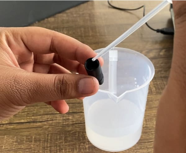
Now if you want to test the sensor, you can dip the probe in water and start checking the reading.

If you want to make zero dissolved oxygen water, you can add sodium sulfite(Na2SO3) into the water until it is saturated. This can consume all the oxygen in the water to obtain the zero dissolved oxygen liquid.
The dissolve oxygen value may differ depending upon the parameters like Aquatic life, Elevation, Salinity (saltiness), Temperature, Turbulence & Vegetation. For measuring the water quality, you can measure the Water Ph, Turbidity, TDS & Temperature as well. You can add Ph Sensor, Turbidity Sensor, TDS & Temperature Sensor to this circuit.
Video Tutorial & Guide


")


3 Comments
How can i get the mg/l value? Is it written here divide by 1000. But i can’t find out where to put divide in the code.
I have followed the tutorial correctly using clean water with a temperature of around 25 degrees and put NaOH liquid on the probe cap. but why the output value of adc raw and adc voltage is not worth 27 and 141, the output value of adc is very far from what is expected to reach 100 – 1000 as a result the DO output value is irregular. please help, thank you
Hi!
Why “35” on below code?
uint16_t V_saturation = (uint32_t)CAL1_V + (uint32_t)35 * temperature_c – (uint32_t)CAL1_T * 35;