

Overview:
In this guide, we will explore how to interface a Soil Moisture & Temperature Sensor with Arduino using the RS485 protocol. This setup will allow us to monitor the moisture content and temperature of the soil, which are crucial parameters for agriculture and gardening.
Soil moisture sensors measure the volumetric water content in soil. By understanding the moisture levels, farmers and gardeners can make informed decisions about irrigation, ensuring optimal plant growth. The temperature of the soil also plays a significant role in plant health, affecting root growth and nutrient uptake.

For this project, we will utilize the Renkeer Soil Moisture & Temperature Sensor, which is specifically designed for in-ground measurements. This sensor can measure soil moisture levels ranging from 0% to 100% and soil temperature from -40°C to 60°C with impressive accuracy. Its low-power consumption makes it ideal for remote locations, powered by solar panels or batteries. Earlier, we used Capacitive Soil Moisture Sensor and also Resistive Soil Moisture Sensor, but they are not industrial graded.
Therefore we are using Industrial Grade Soil Sensor for this project. To interface the sensor with the Arduino, we will use the RS485 communication protocol. The data from the Soil Moisture & Temperature Sensor will be presented on an OLED screen connected to the Arduino.
Bill of Materials
For this project, we need the following components. You can purchase all these components from the given links.
| S.N. | Components | Quantity | Purchase Link |
|---|---|---|---|
| 1 | Arduino Nano Board | 1 | Amazon | AliExpress | SunFounder |
| 2 | Soil Temperature Humidity Sensor | 1 | Renkeer |
| 3 | 0.96" I2C OLED Display | 1 | Amazon | AliExpress | SunFounder |
| 4 | MAX485 Module | 1 | Amazon | AliExpress | SunFounder |
| 5 | 5V Power Supply | 1 | Amazon | AliExpress | SunFounder |
| 6 | Jumper Wires | 10 | Amazon | AliExpress | SunFounder |
| 7 | Breadboard | 1 | Amazon | AliExpress | SunFounder |
Soil Moisture & Temperature Sensor
The Soil Temperature and Humidity Sensor is a device designed to check soil warmth and wetness.

It’s compared with high-quality German sensors to make sure it’s accurate. This sensor is quick to give results and works reliably. It’s good for all soil types, even those with salts. One thing to note is when measuring frozen ice layers, the water value might be low and not accurate, so users need to adjust for that. One of its best features is that it can be left in the ground for a long time. It won’t corrode and is completely waterproof.
This sensor is useful in many areas. It’s great for science projects, helping farmers save water, and making sure plants in greenhouses grow well. It’s also used in places like sewage plants and grain storage.
Technical Parameters
- Supply power: 4.5~30V DC
- Power consumption: 0.4W
- Moisture measurement range: 0~100% RH
- Temperature measurement range: -40℃~60℃(personal)
- Moisture accuracy: ±3%RH(default)
- Temperature accuracy: ±0.5℃(default)
- Work environment: -20℃~60℃,0~80%RH
- Output signal: RS485
- Parameter configuration: software
Physical Parameters
- Probe length: 70 mm
- Probe diameter: 3 mm
- Probe material: 304 stainless steel
- Sealing material: Epoxy resin (black flame retardant)
- Cable length: standard two meters (RVV 4 * 0.3)
- Protection class: IP68
How To Use
1. Speed Measurement Method:
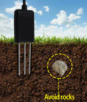
Choose the right spot for measurement, avoiding areas with stones. Ensure the needle doesn’t hit any hard objects. Clear the topsoil up to the desired measurement depth, but keep the soil below compact.
Insert the sensor vertically into the soil without shaking it side to side. For accurate results, it’s recommended to take an average from several measurements at a small point.
2. Buried measurement method:
For accurate measurements using the probe, dig a vertical pit with a diameter exceeding 20cm. Once dug, the probe should be inserted horizontally into the pit wall at the desired depth.
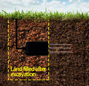
After inserting the probe, ensure the pit is filled tightly and allowed to stabilize. This stabilization can take several days, months, or even longer. Once stable, you can begin extended measurement and recording sessions.
Sensor Pinout
The Soil Moisture & Temperature Sensors works on RS485 Protocol and hence can communicate with easily with Arduino, ESP32 or any other microcontrollers using RS485 Module.
Here are the 4 wires for the sensor.

- Brown Wire: VCC (10-30V)
- Black Wire: GND
- Yellow Wire: RS485-A
- Blue Wire: RS485-B
Data Frame Format Definition & Communication Protocol
Data frame format definition
Using the Modbus-RTU communication protocol, the format is as follows:
- Initial structure ≥ 4 bytes of time
- Address code = 1 byte
- Function code = 1 byte
- Data area = N bytes
- Incorrect revision = 16 byte CRC code
- Ending structure ≥4 byte time
Host query frame structure:
| Address Code | Function Code | Register Origin Address | Register Length | Check code Low Bit | Check Code High Bit |
| 1 byte | 1 byte | 2 bytes | 2 bytes | 1 byte | 1 byte |
Slave response frame structure:
| Address Code | Function Code | Effective Bytes | Data Area 1 | Data Area 2 | Data Area N | Revision Code |
| 1 byte | 1 byte | 1 byte | 2 bytes | 2 bytes | 2 bytes | 2 bytes |
Read the Soil Moisture & Temperature Value
Inquiry frame:
| Address Code | Function Code | Initial Address | Data Length | Check code Low Bit | Check Code High Bit |
| 0x01 | 0x03 | 0x00 0x00 | 0x00 0x02 | 0xC4 | 0x0B |
Response frame:
| Address Code | Function Code | Returns Byte Number | Humidity Number | Temperature Number | Check code low bit | Check code high bit |
| 0x01 | 0x03 | 0x04 | 0x02 0x92 | 0xFF 0x9B | 0x5A | 0x3D |
Temperature calculation :
When temperature is under 0 ℃, the temperature date will be updated in complement code.
Temperature: FF9B H(hexadecimal)= -101 => temperature = -10.1℃
Humidity calculation:
Humidity: 292 H (hexadecimal)= 658 => humidity = 65.8%RH
Interfacing Soil Moisture & Temperature Sensor with Arduino
Now lets interface the Soil Humidity & Temperature Sensor with Arduino & start measuring the Soil Moisture and Temperature.
Here is the schematic for the project.

The Soil Sensor communicates with a Microcontroller using RS485 protocol. Hence we used MAX485 Module for this project. The MAX485 is a popular RS-485 transceiver chip commonly used for serial communication. When interfacing the MAX485 with an Arduino, you’ll typically be dealing with half-duplex communication, where data transmission and reception occur at different times.

Here is a connection mapping between MAX485 & Arduino.
- VCC (MAX485) -> 5V (Arduino)
- GND (MAX485) -> GND (Arduino)
- RO (MAX485) -> 2 (Digital Pin of Arduino)
- DI (MAX485) -> 3 (Digital Pin of Arduino)
- RE (MAX485) -> 8 (Digital Pin of Arduino)
- DE (MAX485) -> 7 (Digital Pin of Arduino)

Here is a connection mapping between MAX485 & Soil Humidity Temperature Sensor.
- VCC -> 5V (Soil Sensor)
- GND -> GND (Soil Sensor)
- A (MAX485) -> Soil Sensor A Pin (Yellow Color)
- B (MAX485) -> Soil Sensor B Pin (Blue Color)

You may use a breadboard for assembly and a jumper wires for connecting the sensor and RS485 Module with Arduino.
Source Code/Program for Reading Soil Moisture & Temperature
After assembling the sensor as per the circuit diagram above, lets move to the coding part of this project. According to the above table the inquiry frame for getting the Sensor reading hexadecimal is as follows:
|
1 |
0x01, 0x03, 0x00, 0x00, 0x00, 0x02, 0xC4, 0x0B |
The sensor communicates at a baudrate of 4800. We have set the same parameter in the code to get the required reading.
Copy the following code and paste it on your Arduino IDE.
|
1 2 3 4 5 6 7 8 9 10 11 12 13 14 15 16 17 18 19 20 21 22 23 24 25 26 27 28 29 30 31 32 33 34 35 36 37 38 39 40 41 42 43 44 45 46 47 48 49 50 51 52 53 54 55 56 57 58 59 60 61 62 63 64 65 66 67 68 69 70 71 72 73 74 75 76 77 78 79 80 81 82 83 84 85 86 87 88 89 90 91 92 93 94 95 96 97 98 99 100 101 102 103 104 105 106 107 108 109 110 111 112 113 114 115 116 117 118 119 120 121 122 123 124 125 126 127 128 129 130 131 132 133 134 135 136 137 138 139 140 141 |
#include <SoftwareSerial.h> #include <Adafruit_SSD1306.h> // Include the Adafruit SSD1306 library to interact with the display #define SCREEN_WIDTH 128 // Set the width and height of the display in pixels #define SCREEN_HEIGHT 64 #define OLED_RESET -1 // Set the OLED reset pin to -1 if it shares the Arduino reset pin #define SCREEN_ADDRESS 0x3C // Set the address of the screen as specified in its datasheet // Create an Adafruit_SSD1306 object called display Adafruit_SSD1306 display(SCREEN_WIDTH, SCREEN_HEIGHT, &Wire, OLED_RESET); // Define the pins for RS485 communication #define RE 8 #define DE 7 // Request frame for the soil sensor const byte soilSensorRequest[] = {0x01, 0x03, 0x00, 0x00, 0x00, 0x02, 0xC4, 0x0B}; byte soilSensorResponse[9]; SoftwareSerial mod(2, 3); // Software serial for RS485 communication void setup() { Serial.begin(9600); // Initialize serial communication for debugging mod.begin(4800); // Initialize software serial communication at 4800 baud rate pinMode(RE, OUTPUT); // Set RE pin as output pinMode(DE, OUTPUT); // Set DE pin as output // Start the display, looping forever if it fails if (!display.begin(SSD1306_SWITCHCAPVCC, SCREEN_ADDRESS)) { Serial.println(F("SSD1306 allocation failed")); for (;;); } display.clearDisplay(); // Clear the display and display the cleared screen display.display(); delay(500); } void loop() { // Start the transmission mode for RS485 digitalWrite(DE, HIGH); digitalWrite(RE, HIGH); delay(10); // Send the request frame to the soil sensor mod.write(soilSensorRequest, sizeof(soilSensorRequest)); // End the transmission mode and set to receive mode for RS485 digitalWrite(DE, LOW); digitalWrite(RE, LOW); delay(10); // Wait for the response from the sensor or timeout after 1 second unsigned long startTime = millis(); while (mod.available() < 9 && millis() - startTime < 1000) { delay(1); } if (mod.available() >= 9) // If valid response received { // Read the response from the sensor byte index = 0; while (mod.available() && index < 9) { soilSensorResponse[index] = mod.read(); Serial.print(soilSensorResponse[index], HEX); // Print the received byte in HEX format Serial.print(" "); index++; } Serial.println(); // Parse and calculate the Moisture value int Moisture_Int = int(soilSensorResponse[3] << 8 | soilSensorResponse[4]); float Moisture_Percent = Moisture_Int / 10.0; Serial.print("Moisture: "); Serial.print(Moisture_Percent); Serial.println(" %RH"); // Parse and calculate the Temperature value int Temperature_Int = int(soilSensorResponse[5] << 8 | soilSensorResponse[6]); float Temperature_Celsius = Temperature_Int / 10.0; // Check if temperature is negative and convert accordingly if (Temperature_Int > 0x7FFF) { Temperature_Celsius = 0x10000 - Temperature_Int; Temperature_Celsius = -Temperature_Celsius / 10.0; } Serial.print("Temperature: "); Serial.print(Temperature_Celsius); Serial.println(" °C"); // Clear the display and set the text color display.clearDisplay(); display.setTextColor(SSD1306_WHITE); display.setTextSize(1); display.setCursor(25, 0); display.print("Soil Moisture"); display.setTextSize(2); display.setCursor(30, 12); display.print(Moisture_Percent); display.setTextSize(1); display.print("% "); display.setTextSize(1); display.setCursor(30, 35); display.print("Temperature"); display.setTextSize(2); display.setCursor(30, 47); display.print(Temperature_Celsius); display.setTextSize(1); display.print("*C"); display.display(); } else { // Print error message if no valid response received Serial.println("Sensor timeout or incomplete frame"); display.clearDisplay(); display.setTextColor(SSD1306_WHITE); display.setTextSize(1); display.setCursor(0, 0); display.print("Sensor timeout"); display.display(); } delay(1000); // Wait for a second before the next loop iteration } |
Testing & Results
After uploading the code, the setup is ready for test. The OLED will immediately display the temperature and Soil Moisture Value.

The OLED Display shows room temperature value as some number, which is correct. For the Soil Moisture part, the Soil Moisture appears as zero. This is because the Sensor is kept in dry air.
To get the readings of soil moisture, dip the metallic part of the sensor in Soil.

When the water content in the Soil is increased, there is rise in Soil Moisture Value displayed on OLED Screen.

For field and practical testing, you can dip the Sensor in the Soil.

This is how you can use the Soil Humidity and Temperature Sensor with Arduino to read the Soil Moisture & Temperature Value.
Video Tutorial & Guide

Conclusion
In conclusion, the guide provided a comprehensive overview of interfacing the Renkeer Soil Moisture & Temperature Sensor with Arduino through the RS485 protocol. This combination offers a powerful tool for real-time monitoring of soil conditions, essential for effective agriculture and gardening. With its impressive accuracy and range, the sensor is especially suitable for remote areas, thanks to its low power consumption.
Displaying the data on an OLED screen ensures clear visibility of readings, paving the way for improved crop management and efficient water usage. This system is not only technologically advanced but also a significant step towards sustainable farming practices.

")


