

Overview:
In this project, we will design an RFID Based Door Lock Security System utilizing the RC5222 Module and Arduino. As the world advances towards more sophisticated security measures, RFID (Radio Frequency Identification) technology has emerged as a preferred choice for many security applications. Unlike conventional lock and key systems, RFID security systems employ electromagnetic fields to identify and track tags attached to objects, making them more efficient and less susceptible to duplication.

By coupling the versatile Arduino microcontroller with the RC5222 RFID module, we can develop a robust and responsive door lock system. When an RFID tag comes in proximity to the reader, the Arduino evaluates the tag’s information against the stored data to ascertain if access should be permitted or restricted. This project provides a practical insight into the workings of RFID technology, demonstrating the synergy between Arduino and the RC5222 module in crafting security solutions.
Earlier, we build Security system projects like Password Based Security System and also Fingerprint Biometric Security System using Arduino. You may check that as well.
Bill of Materials
Following are the components required for building this RFID Based Door Lock Security System Project using Arduino. You can purchase all these components from the given links.
| S.N. | Components Name | Quantity | Purchase Links |
|---|---|---|---|
| 1 | Arduino Nano Board | 1 | Amazon | AliExpress | SunFounder |
| 2 | RFID Module RC522 | 1 | Amazon | AliExpress | SunFounder |
| 3 | 16x2 I2C LCD Display | 1 | Amazon | AliExpress | SunFounder |
| 4 | 12V Solenoid Lock | 1 | Amazon | AliExpress |
| 5 | LED 5mm Any Color | 2 | Amazon | AliExpress | SunFounder |
| 6 | Buzzer 5V | 1 | Amazon | AliExpress | SunFounder |
| 7 | 1 Channel Relay Module | 1 | Amazon | AliExpress | SunFounder |
| 8 | Resistor 1K | 2 | Amazon | AliExpress | SunFounder |
| 9 | 7805 Voltage Regulator IC | 1 | Amazon | AliExpress |
| 10 | Capacitor 100uF/35V | 1 | Amazon | AliExpress | SunFounder |
| 11 | 12V Power Supply | 1 | Amazon | AliExpress | SunFounder |
| 12 | Connecting Wires | 20 | Amazon | AliExpress | SunFounder |
| 13 | Breadboard | 1 | Amazon | AliExpress | SunFounder |
Block Diagram & System Operations
Here’s the block diagram of the RFID Based Door Lock Security System using Arduino:

Components Used
The system employs an Arduino Microcontroller, an RFID Reader, and several other components which are detailed below:
- Arduino: This acts as the brain of the system. It receives signals from the RFID reader, processes them, and subsequently sends commands to either grant or deny access.
- LCD Display: This display module offers feedback to the user. It can showcase messages such as “Access Granted”, “Access Denied”, or “Scan your RFID card”.
- RFID Reader: This component reads the RFID card or tag presented by the user. If the RFID data aligns with the stored information, it sends a signal to the Arduino for further action. The RC522 SPI Module is the most popular module in the market which has been used in this project.
- LED Indicator: This provides visual feedback about the system’s status. For instance, a green LED might indicate successful access, while a red LED could signify denied access.
- Buzzer: An auditory component that can sound alerts or notifications based on the system’s status or user interactions.
- Relay: This electrically operated switch is activated when the Arduino sends a command to grant access.
- Solenoid Lock: An electronic lock mechanism that can be locked or unlocked when powered. The relay, when activated, supplies power to this lock, causing it to unlock.
System Operation
The RFID Based Door Lock Security System is engineered to offer secure access control through RFID card verification. Central to the system are an RFID reader, an Arduino microcontroller, a relay, a solenoid lock, an LCD display, an LED indicator, and a buzzer. Users mainly interact with the system by presenting their RFID cards to the reader and receiving feedback via the LCD display and LED indicator.
When a user scans their RFID card, the reader captures the card’s data and forwards it to the Arduino for validation. The Arduino then compares this data with the stored RFID information. If there’s a match, the Arduino triggers the relay, which subsequently powers the solenoid lock, unlocking it. Throughout this procedure, the LCD display and LED indicator provide real-time feedback to the user, indicating actions required or the outcome of the verification, such as “Access Granted” or “Access Denied”.
Circuit Diagram of RFID Door Lock Security System using Arduino
Here’s the circuit diagram of the RFID Based Door Lock Security System:

Let us take a closer look at the connection between various components in this project.
Arduino – LCD Connection:
- SDA (Serial Data): Connected to the A4 pin of the Arduino.
- SCL (Serial Clock): Connected to the A5 pin of the Arduino.
- VCC: Connected to the 5V pin of the Arduino, providing power to the LCD.
- GND (Ground): This is connected to the GND pin of the Arduino
LED Indicators:
- Led1: Indicates the Lock Status and is connected to the D2 pin of the Arduino.
- Led2: Another indicator for the Unlock status is connected to the D3 pin of the Arduino.
RFID MFRC522 Module
- SDA: Connected to D10 of Arduino
- SCK: Connected to D13 of Arduino
- MOSI: Connected to the D11 pin of Arduino
- MISO: Connected to the D12 pin of Arduino
- GND: Connected to GND of Arduino
- RST: Connected to the D9 pin of Arduino
- 3.3V: Connected to the 3.3V pin of Arduino
Relay Module
- VCC: Connected to 5V of Arduino
- GND: Connected to GND Pin
- IN: Connected to D6 of Arduino
- COM: Connected to Solenoid Lock
- NC: Connected to 12V
For the Power Supply unit, the entire device is powered using a 12V DC Power Adapter. The 7805 Voltage regulator IC power the Relay and relay using the 5V output of the 7805 regulator. The 12V Supply is also connected to the Vin Pin of Arduino Nano. The 100uF/35V Electrolytic Capacitor is used for Voltage Stability at Power Supply Pins.

All the connection can be done in breadboard as per circuit diagram.
Source Code/Program
Let us move to the programming part of “RFID Based Door Lock Security System” using Arduino IDE. The code requires few libraries for compilation. You need to install the libraries first.
Download the following libraries and add it to the Arduino Library folder.
Apart from above two librarries, we need a header file “pitches.h“. This header file has a definitions for musical note frequencies in Hertz, which can be used to play melodies using a piezo buzzer or other sound-producing device.
Copy the code from the following link: pitches.h and save it to the sketch folder with the name pitches.h.

Here is the completed code for the RFID RFID Based Door Lock Security System using Arduino. Copy the code and paste it to the Arduino IDE.
|
1 2 3 4 5 6 7 8 9 10 11 12 13 14 15 16 17 18 19 20 21 22 23 24 25 26 27 28 29 30 31 32 33 34 35 36 37 38 39 40 41 42 43 44 45 46 47 48 49 50 51 52 53 54 55 56 57 58 59 60 61 62 63 64 65 66 67 68 69 70 71 72 73 74 75 76 77 78 79 80 81 82 83 84 85 86 87 88 89 90 91 92 93 94 95 96 97 98 99 100 101 102 103 104 105 106 107 108 109 110 111 112 113 114 115 116 117 118 119 120 121 122 123 124 125 126 127 128 129 130 131 132 133 134 135 136 137 138 139 140 141 142 143 144 145 146 147 148 149 150 151 152 153 154 155 156 157 158 159 160 161 162 163 164 165 166 167 168 169 170 171 172 173 174 175 176 177 178 179 180 181 182 183 184 185 186 187 |
// Include necessary libraries for RFID, SPI, pitches, and LCD #include <RFID.h> #include <SPI.h> #include "pitches.h" #include <LiquidCrystal_I2C.h> // Define pins for RFID, Relay, LEDs, and Buzzer #define SS_PIN 10 #define RST_PIN 9 #define RELAY_PIN 6 #define Red_LED 2 #define Green_LED 3 #define Buzzer 4 // Initialize LCD with I2C address LiquidCrystal_I2C lcd(0x27, 16, 2); // Initialize RFID with SS and RST pins RFID rfid(SS_PIN, RST_PIN); // Define authorized RFID tag int My_RFID_Tag[5] = {0x8A, 0x30, 0x03, 0x80, 0x39}; boolean My_Card = false; // Define melodies and note durations for buzzer int melody[] = {NOTE_C4, NOTE_G3, NOTE_G3, NOTE_A3, NOTE_G3, 0, NOTE_B3, NOTE_C4}; int noteDurations[] = {4, 8, 8, 4, 4, 4, 4, 4}; int welcomeMelody[] = {NOTE_C4, NOTE_D4, NOTE_E4}; int welcomeDurations[] = {4, 4, 4}; void setup() { // Set pin modes for LEDs, Buzzer, and Relay pinMode(Red_LED, OUTPUT); pinMode(Green_LED, OUTPUT); pinMode(Buzzer, OUTPUT); pinMode(RELAY_PIN, OUTPUT); digitalWrite(RELAY_PIN, HIGH); // Set relay to normally closed state // Initialize serial communication for debugging and LCD for display Serial.begin(9600); lcd.init(); lcd.backlight(); // Initialize SPI bus and RFID module SPI.begin(); rfid.init(); } void loop() { // Assume card is authorized initially My_Card = true; digitalWrite(RELAY_PIN, HIGH); // Lock the door by default lcd.clear(); lcd.print(" Put Your Card "); // Check for the presence of an RFID card and read its serial number if (rfid.isCard() && rfid.readCardSerial()) { playWelcomeMelody(); // Play a welcoming tune displayCardInfo(); // Display card's unique ID checkCardAuthorization(); // Check if the card is authorized } rfid.halt(); // Stop reading the card } // Function to display the RFID card's unique ID on LCD and Serial monitor void displayCardInfo() { lcd.clear(); lcd.print("UNIQUE ID is:- "); delay(500); lcd.setCursor(0, 1); for (int i = 0; i < 5; i++) { Serial.print(rfid.serNum[i], HEX); Serial.print(" "); lcd.print(rfid.serNum[i], HEX); lcd.print(" "); } delay(500); } // Function to check if the read RFID card is authorized void checkCardAuthorization() { for (int i = 0; i < 5; i++) { if (My_RFID_Tag[i] != rfid.serNum[i]) { My_Card = false; break; } } Serial.println(); delay(1000); My_Card ? grantAccess() : denyAccess(); // Grant or deny access based on card authorization } // Function to grant access if the card is authorized void grantAccess() { Serial.println("\nWelcome To Your Room"); lcd.clear(); lcd.print("Welcome to Your"); lcd.setCursor(0, 1); lcd.print("Room!"); delay(2000); digitalWrite(Green_LED, HIGH); // Turn on green LED playMelody(); // Play a melody openDoor(); // Unlock the door } // Function to play a melody when access is granted void playMelody() { for (int i = 0; i < 2; i++) { for (int thisNote = 0; thisNote < 12; thisNote++) { int noteDuration = 1000 / noteDurations[thisNote]; tone(Buzzer, melody[thisNote], noteDuration); delay(noteDuration * 1.30); noTone(Buzzer); } delay(500); } } // Function to unlock the door and start a countdown before locking it again void openDoor() { digitalWrite(RELAY_PIN, LOW); // Unlock the door delay(200); lcd.clear(); for (int i = 10; i > 0; i--) { lcd.print("Door will close"); lcd.setCursor(0, 1); lcd.print("in "); lcd.print(i); lcd.print(" Sec HurryUp!"); delay(1000); lcd.clear(); } digitalWrite(RELAY_PIN, HIGH); // Lock the door again digitalWrite(Green_LED, LOW); // Turn off green LED delay(200); lcd.clear(); lcd.print("Door is Close"); lcd.setCursor(0, 1); lcd.print("Now!"); delay(2000); } // Function to deny access if the card is unauthorized void denyAccess() { Serial.println("\nGet Out of Here !"); lcd.clear(); lcd.print("Card NOT FOUND!"); lcd.setCursor(0, 1); lcd.print("Get Out of Here!"); for (int i = 0; i < 7; i++) { digitalWrite(Buzzer, HIGH); // Sound the buzzer digitalWrite(Red_LED, HIGH); // Turn on red LED delay(500); digitalWrite(Buzzer, LOW); // Turn off buzzer digitalWrite(Red_LED, LOW); // Turn off red LED delay(500); } delay(1000); } // Function to play a welcome melody while the card is being identified void playWelcomeMelody() { for (int i = 0; i < 3; i++) { int noteDuration = 1000 / welcomeDurations[i]; tone(Buzzer, welcomeMelody[i], noteDuration); delay(noteDuration * 1.30); noTone(Buzzer); } } |
Select the Arduino Nano Board from the Board list and also select the COM port. Then you can simply upload the code to the Arduino Nano Board.
Setting Up the Master RIFD Tag for Unlocking Door
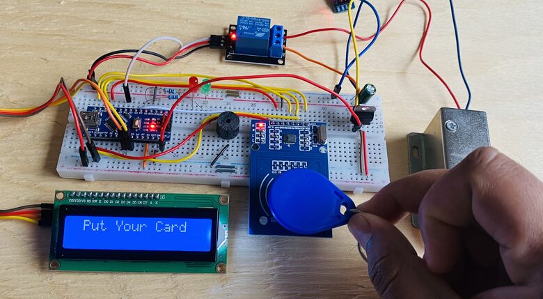
After uploading the code, the first step would be to set the “Master RFID Tag”, which can only unlock the door. To do that scan the RFID Card as shown.
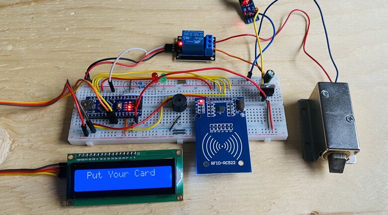
Place your card of RFID Reader.

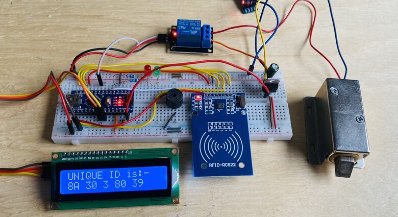
The LCD screen will display the RFID Tag number as shown below.
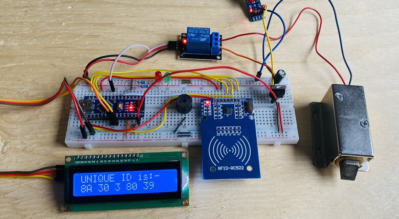
The tag number here is in HEX format and need to be noted down as this would be used in the code.
|
1 2 |
// Define authorized RFID tag int My_RFID_Tag[5] = {0x8A, 0x30, 0x03, 0x80, 0x39}; |
In the code part, replace the Tag ID in the above line. Then reupload the code.
Working of RFID Door Lock Security System using Arduino
To test the system’s functionality, position your card for scanning.
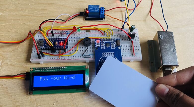
The LCD will display the RFID tag number.

If the scanned RFID tag number does not match the stored RFID tag, the door will remain locked.
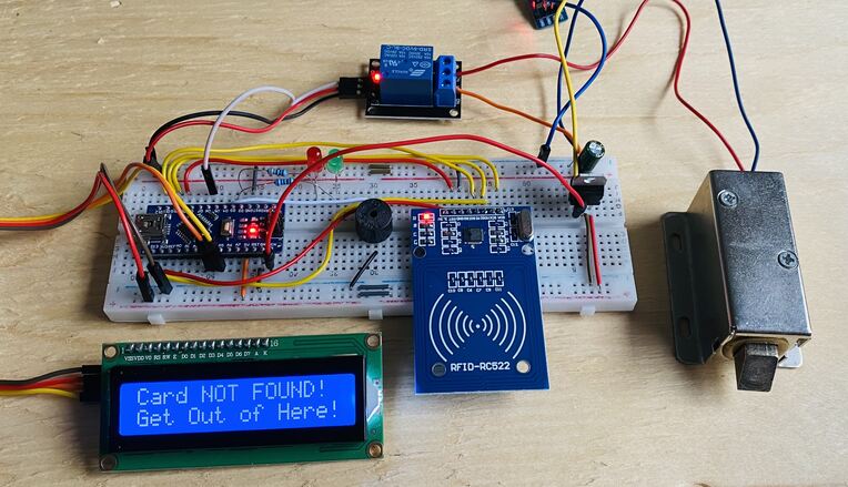
Concurrently, the LCD will show a specific message, the red LED will illuminate, and the buzzer will play warning tones.
To begin, scan the designated RFID tag intended for unlocking the door.
Upon scanning, the LCD will display the RFID tag number.
If the tag matches the stored data, the LCD will greet you with a “Welcome to your Room” message. Simultaneously, the green LED will light up, and the buzzer will play a welcoming melody.
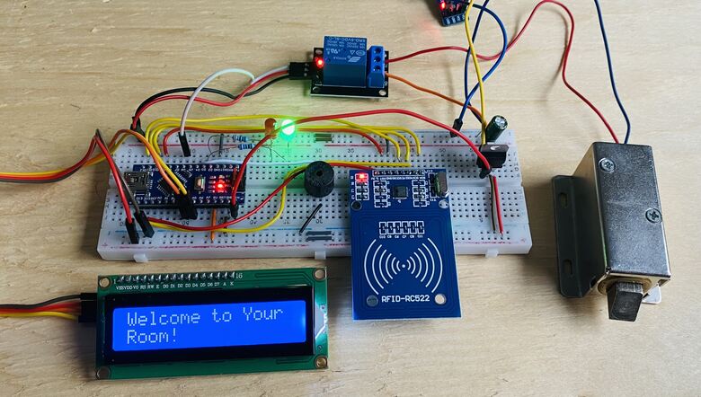
Following this, the relay activates, powering the solenoid lock and unlocking the door. The LCD will then showcase a 10-second countdown timer.
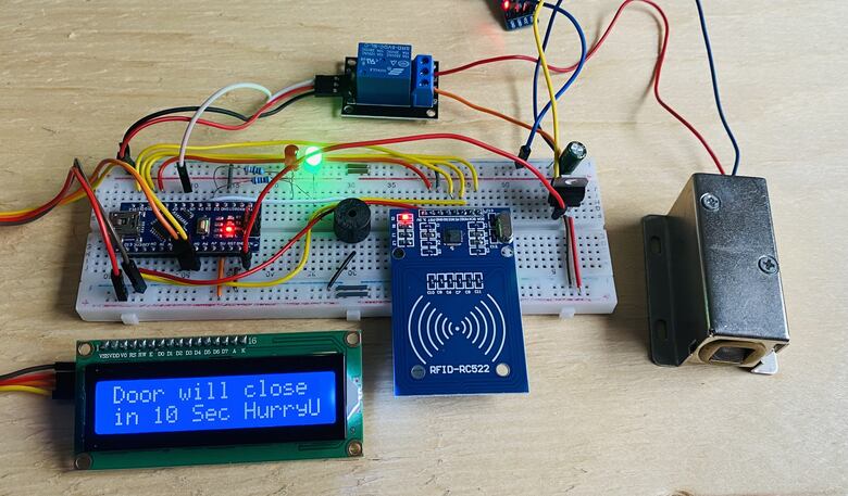
Once the 10 seconds elapse, the door will automatically lock again, as the solenoid will no longer receive power from the relay.

This process outlines the functionality of the RFID-based Door Lock Security System, which can be effortlessly assembled using an Arduino board.
Video Tutorial & Guide

Conclusion
In our exploration of modern security solutions, we successfully designed and implemented an RFID Based Door Lock Security System using the RC5222 Module and Arduino. The fusion of RFID technology, known for its efficiency and resistance to duplication, with the adaptability of the Arduino microcontroller, has paved the way for a reliable and advanced security measure. Our system efficiently evaluates the information from an RFID tag when placed near the reader, granting or denying access based on the stored data.
This project not only showcased the potential of RFID technology but also highlighted the seamless integration capabilities of the Arduino with the RC5222 module. Such innovations underscore the potential of combining traditional security measures with modern technology, offering a glimpse into the future of security systems.

")


