

Overview
In this article, we will learn how we can create an OTAA-based LoRaWAN Node with Arduino & LoRa Module SX1276. In previous tutorial, we learned how to setup Dragino LPS8 LoRaWAN Gateway with The Things Network Server. We also learned about the Ra-07 LoRaWAN Node and the method to send sensor data to The Things Network Server using the LoRaWAN Gateway.
This tutorial covers the method to develop a DIY LoRaWAN End Node which can be activated in OTAA mode using the SX1276 LoRa module and Arduino Pro Mini. The node can publish a “hello world!” message to The Things Network Dashboard. The data being transmitted over the LoRaWAN is encrypted, so we will learn how to decrypt that data to read the message in a readable format. Check the earlier post to learn how you make ABP Based LoRaWAN Node for activating via ABP Method.
Bill of Materials
We can use a breadboard to test the LoRaWAN product, so following materials can be purchased from the given Amazon link.
| S.N. | Components Name | Quantity | Purchase Links |
|---|---|---|---|
| 1 | Arduino Pro Mini 3.3V Board | 1 | Amazon | AliExpress |
| 3 | FTDI Module | 1 | Amazon | AliExpress |
| 2 | LoRa Module SX1276 | 1 | Amazon | AliExpress |
| 4 | Connecting Wires | 20 | Amazon | AliExpress |
| 5 | Breadboard | 1 | Amazon | AliExpress |
LoRa Module SX1276
You can use any of the SX1276-based LoRa chip which has a frequency of 868MHz. In case you are using a 915MHz Gateway, you can use SX1276 with a 915MHz frequency version. In this tutorial, we are using the LPS8 LoRaWAN gateway with an 868MHz frequency.

The SX1276 is a LoRa chip developed by Semtech. The SX1276 incorporates the LoRa spread spectrum modem which is capable of achieving a significantly longer range than existing systems based on FSK or OOK modulation. At maximum data rates of LoRa, the sensitivity is 8dB better than FSK. But using a low-cost bill of materials with a 2Oppm XTAL LoRa can improve receiver sensitivity by more than 20dB compared to FSK.
SX1276 Pinout
In this tutorial we are using SX1276 chip manufactured by Gplus-IoT. The Gplus-IoT LoRa Module SX1276 has total 18 pins whose functionalities are as follows:

Designing SX1276 Breakout Board
The Gplus-IoT SX1276 chip is very tiny in size so its very difficult to interface it with any controller. So I designed a small breakout board using EasyEDA software and converted it into a PCB. The PCB layout looks something like this.

The Gerber File for the PCB is given below. You can simply download the Gerber File and order the PCB from ALLPCB at 1$ only.
You can use this Gerber file to order high quality PCB for this project. To do that visit the ALLPCB official website by clicking here: https://www.allpcb.com/.

You can now upload the Gerber File by choosing the Quote Now option. From these options, you can choose the Material Type, Dimensions, Quantity, Thickness, Solder Mask Color and other required parameters.

After filling all details, select your country and shipping method. Finally you can place the order.

Then I soldered the SX1276 chip into the PCB. The SX1276 chip has a very small gap between the two consecutive pins. So it requires good soldering skills for soldering the components.

Hardware Setup & Connection
Let us see how we can interface SX1276 LoRa Module with Arduino Pro Mini. The question is why we are using Arduino Pro Mini instead of Arduino UNO or Nano. The reason is that LoRa Chip is an SPI-based chip with a 3.3V logic level. To get the 3.3V logic level, we need to use the Arduino board having 3.3V logic. This logic is provided by Arduino Pro Mini Board.
Here is a connection diagram for interfacing SX1276 LoRa Module with Arduino Board. The connection is fairly simple.

Connect all the SPI Pin of SX1276 to Arduino SPI Pin. We all need to connect at least 2 digital input-output pins of SX1276 to Arduino digital pin. In this circuit, we connected the DIO0, DIO1, and DIO2 of SX1276 to Arduino D3, D4, and D5 Pin respectively. The LoRaWAN hardware doesn’t work in ABP & OTAA Mode if these pins are left unconnected.
ABP vs OTAA Activation Method
The LoRaWAN Nodes can be activated via tow methods as ABP Activation of OTAA Activation. Let us understand the differences between ABP and OTAA activation modes for LoRaWAN end devices.
ABP
In ABP activation, a fixed DevAddr and session keys for a pre-selected network are hardcoded into the end device, and they remain the same throughout the lifetime of an ABP end device. With this mode, an end device skips the join procedure which seems to be simpler, but there are quite a few limitations of using ABP.
OTAA
OTAA end devices are provisioned with root keys. In OTAA activation, an end device performs a join procedure with a LoRaWAN network, during which a dynamic DevAddr is assigned to an end device, and root keys are utilized to derive session keys. Hence, DevAddr and session keys change as each new session is established.
Registation of LoRaWAN Node on The Things Network Server
For transmitting the LoRaWAN Node data to TTN(The Things Network), it is necessary to learn the use of TTN in advance, such as how to set an application & activate LoRaWAN Device via OTAA method. After setting your application of TTN, there are three parameters that are important: Device EUI, APP Key, APP EUI.

Enter the TTN website: https://console.thethingsnetwork.org/, and log in your account. Then go to the console, select a cluster to start adding devices. In my case I selected EU cluster.
Select Application on the page and add a new application. Then fill in the application ID and other information, then create it.

Add an End device, select frequency plan, and the LoRaWAN version.
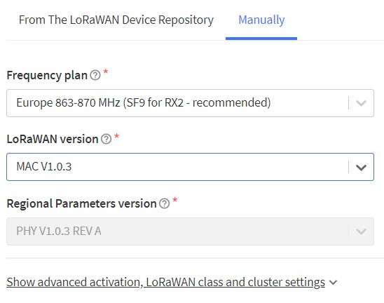
Select manually to choose the active mode for OTAA and LoRaWAN versions, then follow the reminders to type in the parameters. Then generate Device EUI, App EUI and AppKey. Then click on register end devices
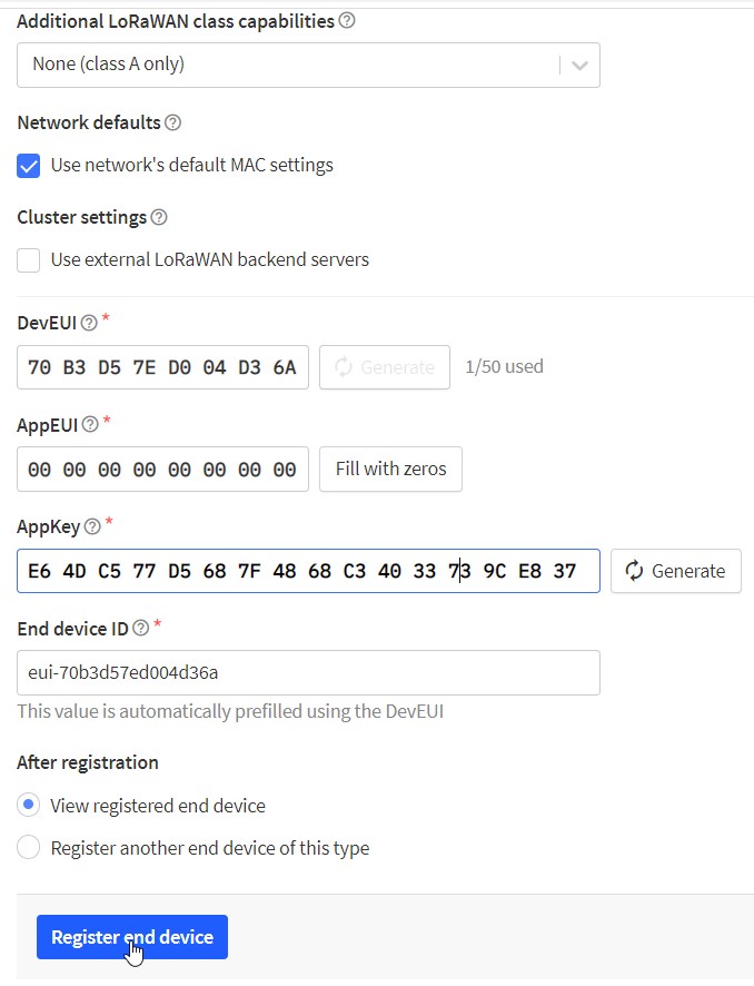
Now the end node is successfully created. Hence you can see three parameters that had to be put into the code.
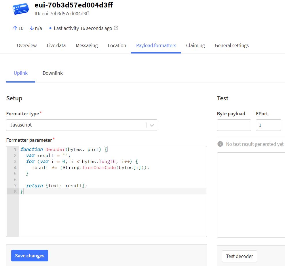
On the device page, it is necessary to set the payload formatters to decode the payload LoRaWAN node transmitted. Choose the Uplink and select the Javascript. Type in the following code and save.
|
1 2 3 4 5 6 7 8 |
function Decoder(bytes, port) { var result = ""; for (var i = 0; i < bytes.length; i++) { result += (String.fromCharCode(bytes[i])); } return {text: result}; } |
Now the TTN application setting is finished.
Source Code & Programming
Now let us program the Arduino Pro Mini to activate the SX1276 Based LoRaWAN node with OTAA method.
For this we will use a readymade library from IBM called as Arduino-LMIC library. Download the library from the Github repository and then install it using the add zip library feature in the Arduino IDE.

Now go to the examples from the file menu and search for the IBM LMIC framework and then open the ttn-otaa example.

Before uploading the code, you need to make some changes to the example code. Add Device EUI, APP Key, APP EUI to the following lines.
|
1 2 3 |
static const u1_t PROGMEM APPEUI[8]={ 0x00, 0x00, 0x00, 0x00, 0x00, 0x00, 0x00, 0x00 }; static const u1_t PROGMEM DEVEUI[8]={ 0x01, 0x00, 0x00, 0x00, 0x00, 0x00, 0x00, 0x00 }; static const u1_t PROGMEM APPKEY[16] = { 0x2B, 0x7E, 0x15, 0x16, 0x28, 0xAE, 0xD2, 0xA6, 0xAB, 0xF7, 0x15, 0x88, 0x09, 0xCF, 0x4F, 0x3C }; |
Also make changes to the Arduino Pins here.
|
1 2 3 4 5 6 |
const lmic_pinmap lmic_pins = { .nss = 6, .rxtx = LMIC_UNUSED_PIN, .rst = 5, .dio = {2, 3, 4}, }; |
You also need to modify some library files to get this code working in case the code fails.
Here is the complete code for the project.
|
1 2 3 4 5 6 7 8 9 10 11 12 13 14 15 16 17 18 19 20 21 22 23 24 25 26 27 28 29 30 31 32 33 34 35 36 37 38 39 40 41 42 43 44 45 46 47 48 49 50 51 52 53 54 55 56 57 58 59 60 61 62 63 64 65 66 67 68 69 70 71 72 73 74 75 76 77 78 79 80 81 82 83 84 85 86 87 88 89 90 91 92 93 94 95 96 97 98 99 100 101 102 103 104 105 106 107 108 109 110 111 112 113 114 115 116 117 118 119 120 121 122 123 124 125 126 127 128 129 130 131 132 133 134 135 136 137 138 139 140 141 142 |
#include <lmic.h> #include <hal/hal.h> #include <SPI.h> // This EUI must be in little-endian format, so least-significant-byte // first. When copying an EUI from ttnctl output, this means to reverse // the bytes. For TTN issued EUIs the last bytes should be 0xD5, 0xB3, // 0x70. static const u1_t PROGMEM APPEUI[8]={ 0x00, 0x00, 0x00, 0x00, 0x00, 0x00, 0x00, 0x00 }; void os_getArtEui (u1_t* buf) { memcpy_P(buf, APPEUI, 8);} // This should also be in little endian format, see above. static const u1_t PROGMEM DEVEUI[8]={ 0x01, 0x00, 0x00, 0x00, 0x00, 0x00, 0x00, 0x00 }; void os_getDevEui (u1_t* buf) { memcpy_P(buf, DEVEUI, 8);} // This key should be in big endian format (or, since it is not really a // number but a block of memory, endianness does not really apply). In // practice, a key taken from ttnctl can be copied as-is. // The key shown here is the semtech default key. static const u1_t PROGMEM APPKEY[16] = { 0x2B, 0x7E, 0x15, 0x16, 0x28, 0xAE, 0xD2, 0xA6, 0xAB, 0xF7, 0x15, 0x88, 0x09, 0xCF, 0x4F, 0x3C }; void os_getDevKey (u1_t* buf) { memcpy_P(buf, APPKEY, 16);} static uint8_t mydata[] = "Hello, world!"; static osjob_t sendjob; // Schedule TX every this many seconds (might become longer due to duty // cycle limitations). const unsigned TX_INTERVAL = 60; // Pin mapping const lmic_pinmap lmic_pins = { .nss = 6, .rxtx = LMIC_UNUSED_PIN, .rst = 5, .dio = {2, 3, 4}, }; void onEvent (ev_t ev) { Serial.print(os_getTime()); Serial.print(": "); switch(ev) { case EV_SCAN_TIMEOUT: Serial.println(F("EV_SCAN_TIMEOUT")); break; case EV_BEACON_FOUND: Serial.println(F("EV_BEACON_FOUND")); break; case EV_BEACON_MISSED: Serial.println(F("EV_BEACON_MISSED")); break; case EV_BEACON_TRACKED: Serial.println(F("EV_BEACON_TRACKED")); break; case EV_JOINING: Serial.println(F("EV_JOINING")); break; case EV_JOINED: Serial.println(F("EV_JOINED")); // Disable link check validation (automatically enabled // during join, but not supported by TTN at this time). LMIC_setLinkCheckMode(0); break; case EV_RFU1: Serial.println(F("EV_RFU1")); break; case EV_JOIN_FAILED: Serial.println(F("EV_JOIN_FAILED")); break; case EV_REJOIN_FAILED: Serial.println(F("EV_REJOIN_FAILED")); break; break; case EV_TXCOMPLETE: Serial.println(F("EV_TXCOMPLETE (includes waiting for RX windows)")); if (LMIC.txrxFlags & TXRX_ACK) Serial.println(F("Received ack")); if (LMIC.dataLen) { Serial.println(F("Received ")); Serial.println(LMIC.dataLen); Serial.println(F(" bytes of payload")); } // Schedule next transmission os_setTimedCallback(&sendjob, os_getTime()+sec2osticks(TX_INTERVAL), do_send); break; case EV_LOST_TSYNC: Serial.println(F("EV_LOST_TSYNC")); break; case EV_RESET: Serial.println(F("EV_RESET")); break; case EV_RXCOMPLETE: // data received in ping slot Serial.println(F("EV_RXCOMPLETE")); break; case EV_LINK_DEAD: Serial.println(F("EV_LINK_DEAD")); break; case EV_LINK_ALIVE: Serial.println(F("EV_LINK_ALIVE")); break; default: Serial.println(F("Unknown event")); break; } } void do_send(osjob_t* j){ // Check if there is not a current TX/RX job running if (LMIC.opmode & OP_TXRXPEND) { Serial.println(F("OP_TXRXPEND, not sending")); } else { // Prepare upstream data transmission at the next possible time. LMIC_setTxData2(1, mydata, sizeof(mydata)-1, 0); Serial.println(F("Packet queued")); } // Next TX is scheduled after TX_COMPLETE event. } void setup() { Serial.begin(115200); Serial.println(F("Starting")); #ifdef VCC_ENABLE // For Pinoccio Scout boards pinMode(VCC_ENABLE, OUTPUT); digitalWrite(VCC_ENABLE, HIGH); delay(1000); #endif // LMIC init os_init(); // Reset the MAC state. Session and pending data transfers will be discarded. LMIC_reset(); // Start job (sending automatically starts OTAA too) do_send(&sendjob); } void loop() { os_runloop_once(); } |
Testing OTAA based LoRaWAN Node
Now we need to test the OTAA based LoRaWAN Node designed SX1276 LoRa Module and Arduino Pro Mini. So, after uploading the above code, open the Serial Monitor in the Arduino IDE.
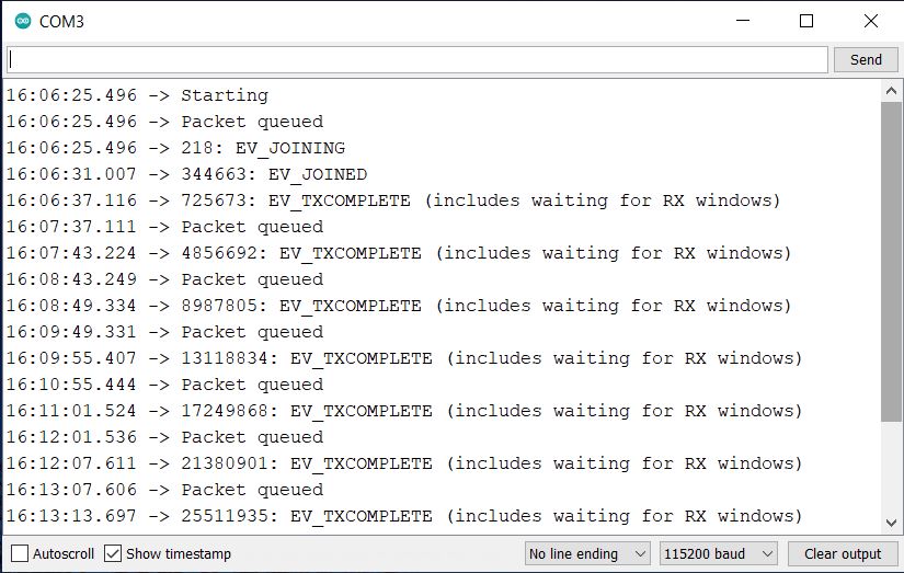
If you see the EV-TXCOMPLETE text on the serial monitor, it means your Lora device is transmitting the Lora data packets.
Now go to applications live data. where you can see the received payload from the device. You can see the data, spreading factor, signal-to-noise ratio, and RSSI of the received data packet.
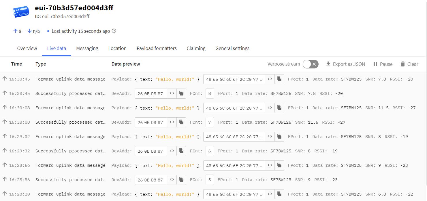
As we already set the payload formatted while setting up The Things Network Dashboard, the data we received is already in decrypted format.
Video Tutorial & Guide

Thus this is how we can create the LoRaWAN Node with Arduino & LoRa Module SX1276 and activate it via the OTAA activation method.


2 Comments
Great tutorial, thanks.
I have got a Rylr896 module and I want to connect it to the things network but I don’t know how to do with this library for the pins doesn’t match. Help me please.
can you please share fritzing part of sx1276 module