

Overview
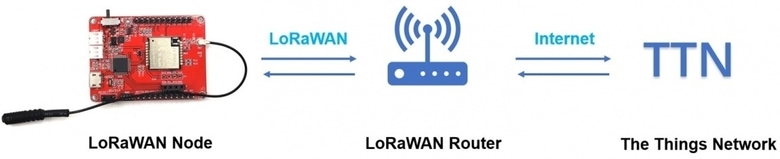
In this project, we will take a look at a Ra-07 LoRaWAN Node from Makerfabs & send some sensor data to The Things Network Server with LPS8 LoRaWAN Gateway from Dragino. The setting configuration and method to connect LoRa Gateway to The Things Network Server is explained in previous article.
LoRa termed as Long Range is a spread spectrum modulation technique derived from chirp spread spectrum (CSS) technology. LoRaWAN is the network system architecture and communication protocol specification for LoRa, developed by the LoRa Alliance. LoRaWAN is a Media Access Control (MAC) layer protocol that enables LoRa in wider applications. The LoRa Alliance defines the networking layer and the system architecture for the network.
The Ra-07 LoRa based board called Maduino Zero LoRaWan is a solution based on the ATSAMD21G18 microcontroller. The Ra-07 Maduino LoRaWan acts as a LoRaWAN node to transmit/receive the local data to the network by connecting LoRaWAN Gateway. With this module, users can easily prototype the LoRaWAN projects without any complications. The board is Arduino compatible hence we can program it using Arduino IDE.
Bill of Materials
We need following tools and components to work with the Ra-07 LoRaWAN Node.
| S.N. | Components Name | Quantity | Purchase Links |
|---|---|---|---|
| 1 | Ra-07 LoRaWAN Node | 1 | Makerfabs |
| 2 | DHT11 Sensor | 1 | Amazon | AliExpress |
| 3 | Jumper Wires | 1 | Amazon | AliExpress |
| 4 | 3.7V, 100mAH Lithium-Ion Battery | 1 | Amazon | AliExpress |
| 5 | Micro-USB Cable | 1 | Amazon | AliExpress |
Ra-07/Ra-07H Module
Ai-Thinker Ra-07/Ra-07H module is a LoRaWAN module that supports long-distance communication, ultra-low power consumption, high sensitivity, and high-cost performance.
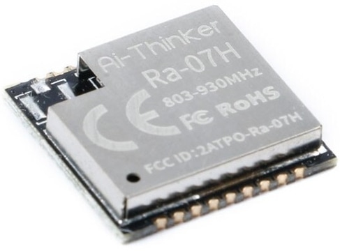
The chip ASR6501 of the module integrates a LoRa radio transceiver, a LoRa modem, and a 32-bit RISC MCU. MCU uses ARM Cortex M0 + core, the operating frequency is 48MHz. The operating frequency range of ASR6501 can support continuous coverage from 150MHz to 960MHz. It supports LoRa modulation and (G)FSK modulation.
Features
-
With super anti-interference ability, it can work normally in a complex interference environments.
-
Minimum receiving sensitivity: -137dBm (SF=12/BW=125KHz)
-
Maximum transmit power +21dBm
-
Working frequency: (Ra-07) 410mhz ~ 525mhz (default), (Ra-07h) 803mhz ~ 930mhz (default)
-
Power supply voltage input: 3.3V
-
Transmitting working current: 107mA (full load power consumption)
-
Receive working current: 6mA
-
Sleep current: 3uA
Ra-07 Based Maduino Zero LoRaWAN Board
The Maduino Zero LoRaWan Board is a solution based on the ATSAMD21G18 microcontroller and LoRaWAN module Ra-07H. The Maduino LoRaWan acts as a LoRaWAN node to transmit/receive the local data to the network by connecting LoRaWAN Gateway. With this module, you can prototype LoRaWAN projects easily in a few hours.
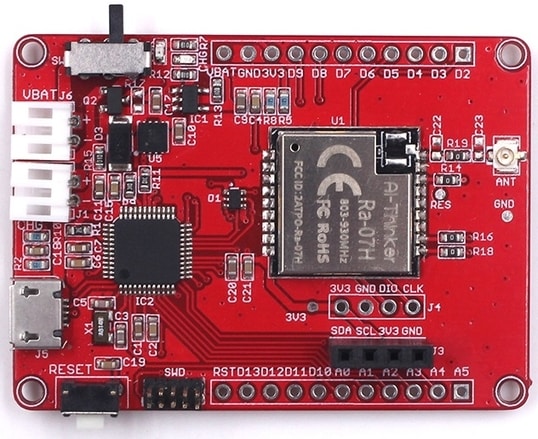
On the top side of the board the Ra-07 LoRa Module is interfaced with ATSAMD21G18 MCU via UART Pins. The Reset switch on the board is used for resetting the microcontroller. The slide witch on the board turns ON/OFF the module. You can either power the board through a single cell 3.7V Lithium-Ion Battery or through a Micro-USB port. The board has a USB to UART Chip, therefore you can directly program the chip through the USB port. On the left and right sides of the board, there are analog/digital input-output pins. OLED pins are given on the board where you can connect an 0.96″ I2C OLED Display.
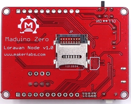
On the backside of the board, there is an SD Card socket, where you can insert an SD Card and use it as a data logger.
The LoRaWAN module Ra-07H has two kinds of firmware which work with 868Mhz frequency and 915Mhz frequency. The default firmware on the board supports 868MHz frequency. If you want to change the firmware of the Ra-07H module, you need a J-Link tool. The firmware is available on GitHub.
Regarding the firmware or coding part, you can use Arduino IDE as Maduino LoRaWan is compatible with Arduino. Using this module we can communicate directly with The Things Network Server. For this, we will need a LoRaWAN router. In this demo, I will use Dragino LP8 Indoor LoRaWAN Gateway.
Specifications
- LoRaWAN Protocol Class A/B/C
- ATSAMD21G18, 32-Bit ARM Cortex M0+
- Interface: I2C/SPI/UART/18*GPIO
- With super anti-interference ability, it can work normally in complex interference environments.
- Minimum Receiving Sensitivity: -137dBm (SF=12/BW=125KHz)
- Maximum Transmit Power +21dBm
- Working Frequency: (Ra-07) 410mhz ~ 525mhz, (Ra-07h) 868mhz (default)
- Power Supply Voltage of the Board: 3.6V~5V(normally 5V)
- Power Supply Voltage of the Module/MCU: normally 3.3V
- Transmitting Working Current: 107mA (full load power consumption)
- Receive Working Current: 6mA
- Sleep Current: 3uA
- LDO: AP7361
- Charger: MCP73831
Preparation before Test & Usage
Hardware
- !!!Note The LoRaWAN node does not transmit the data to TTN by LoRaWAN without the LoRaWAN gateway router which has been set as the TTN gateway.
- 1. The LoRaWAN gateway router used in the demo is a Dragino LPS8.
- 2. Configure the router as a TTN Gateway discussed in the previous post (LP8S Setup)
- 3. Configure the frequency you need.
- Please plug the LoRa antenna into the board.
Software/Coding
- Install Arduino IDE for programming.
Setting up The Things Network
For transmitting the Ra-07 LoRaWAN Node data to TTN(The Things Network), it is necessary to learn the use of TTN in advance, such as how to set an application, etc. After setting your application of TTN, there are three parameters that are important: Device EUI, APP Key, APP EUI.

Enter the TTN website: https://console.thethingsnetwork.org/, and log in your account. Then go to the console, select a cluster to start adding devices. In my case I selected EU cluster.
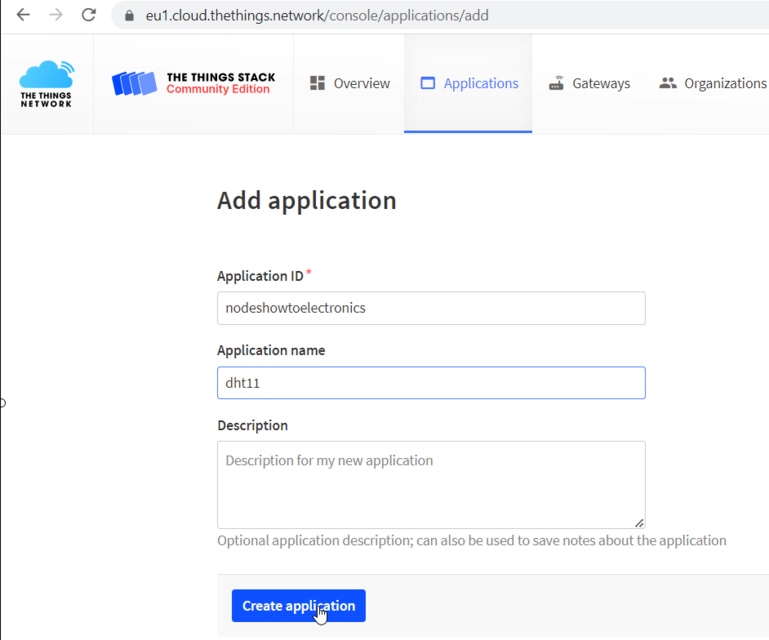
Select Application on the page and add a new application. Then fill in the application ID and other information, then create it.
Add an End device, select frequency plan, and the LoRaWAN version.
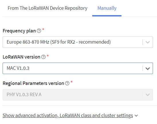
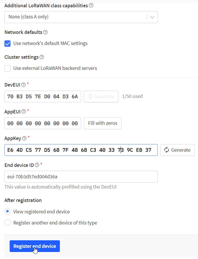
Select manually to choose the active mode for OTAA and LoRaWAN version, then follow the reminders to type in the parameters. Then generate Device EUI, App EUI and AppKey. Then click on register end devices
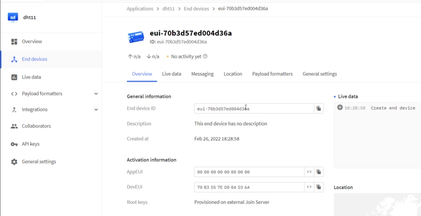
Now the end node is successfully created. Hence you can see three parameters that had to be put into the code.
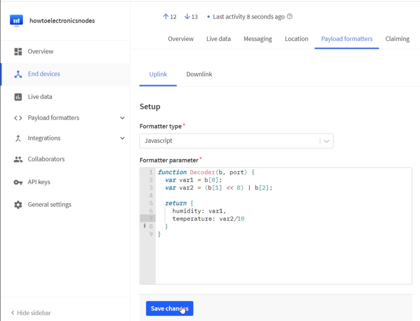
On the device page, it is necessary to set the payload formatters to decode the payload LoRaWAN node transmitted. Choose the Uplink and select the Javascript. Type in the following code and save.
|
1 2 3 4 5 6 7 8 9 |
function Decoder(b, port) { var var1 = b[0]; var var2 = (b[1] << 8) | b[2]; return { Humidity: var1, Temperature: var2/10 } } |
Now the TTN application setting is finished.
Ra-07 Based LoRaWAN Node
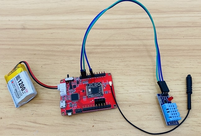
Connect the DHT11 VCC, GND & Signal pin to the board 3.3V, GND & D7 Pin.
Setting up Arduino IDE
The ATSAMD21G18A board isn’t pre-installed in the Arduino IDE. So, we need to install “Arduino Zero Board” from the Board Manager.
Open the Boards Manager From the top Arduino IDE menu, select Tools-> Board-> Boards Manager… to open the Boards Manager dialog box. Then install Arduino SAMD Boards(32-bits ARM Cortex-M0+).

Once, the installation completes, you can now select the Arduino Zero board as shown in the image below. To program this Board you need to connect a Micro USB Data Cable.

Source Code/Program
The complete code for using Ra-07 LoRaWAN Node with LPS8 LoRaWAN Gateway and The Things Network Server is given below.
Copy the following code & replace the three parameters(Device EUI, APP Key, APP EUI) with yours in the code.
|
1 2 3 |
#define DEVEUI "D896E0FF00000241" #define APPEUI "70B3D57ED0041DA0" #define APPKEY "DAC6118A3445572B02EFB73443AF2EB9" |
Now you can verify and upload the code.
|
1 2 3 4 5 6 7 8 9 10 11 12 13 14 15 16 17 18 19 20 21 22 23 24 25 26 27 28 29 30 31 32 33 34 35 36 37 38 39 40 41 42 43 44 45 46 47 48 49 50 51 52 53 54 55 56 57 58 59 60 61 62 63 64 65 66 67 68 69 70 71 72 73 74 75 76 77 78 79 80 81 82 83 84 85 86 87 88 89 90 91 92 93 94 95 96 97 98 99 100 101 102 103 104 105 106 107 108 109 110 111 112 113 114 115 116 |
#include <stdio.h> #include <string.h> #include "DHT.h" #define DEBUG true //get appeui and appkey from the thing network #define DEVEUI "D896E0FF00000241" #define APPEUI "70B3D57ED0041DA0" #define APPKEY "DAC6118A3445572B02EFB73443AF2EB9" #define DHTPIN 7 // Digital pin connected to the DHT sensor #define DHTTYPE DHT11 // DHT 11 DHT dht(DHTPIN, DHTTYPE); int PWR_KEY = 9; int RST_KEY = 6; int LOW_PWR_KEY = 5; bool ModuleState = false; long int runtime = 20000; void setup() { Serial1.begin(115200); SerialUSB.begin(115200); dht.begin(); SerialUSB.println("Now turnning the Lorawan on.Please wait."); pin_init(); SerialUSB.println("Init over"); //set DEVEUI //sendData("AT+CDEVEUI?", 3000, DEBUG); sendData("AT+CDEVEUI=" + String(DEVEUI), 3000, DEBUG); //set APPEUI and APPKEY sendData("AT+CAPPEUI=" + String(APPEUI), 3000, DEBUG); sendData("AT+CAPPKEY=" + String(APPKEY), 3000, DEBUG); //set join mod "OTAA" sendData("AT+CJOINMODE=0", 3000, DEBUG); //join lorawan sendData("AT+CJOIN=1,0,10,1", 30000, DEBUG); //set one message to webgate //sendData("AT+DTRX=1,2,5,FF 00 88", 3000, DEBUG); } void loop() { if (runtime - millis() > 10000) { float h = dht.readHumidity(); float t = dht.readTemperature(); int hum = (int)(h); int temp = (int)(t * 10); char msg[30] = ""; sprintf(msg, "AT+DTRX=1,2,5,%02x%04x", hum, temp); SerialUSB.println(msg); sendData((String)msg, 3000, DEBUG); runtime = millis(); } while (Serial1.available() > 0) { SerialUSB.write(Serial1.read()); yield(); } while (SerialUSB.available() > 0) { Serial1.write(SerialUSB.read()); yield(); } } void pin_init() { pinMode(PWR_KEY, OUTPUT); pinMode(RST_KEY, OUTPUT); pinMode(LOW_PWR_KEY, OUTPUT); digitalWrite(RST_KEY, LOW); digitalWrite(LOW_PWR_KEY, HIGH); digitalWrite(PWR_KEY, HIGH); digitalWrite(PWR_KEY, LOW); delay(3000); digitalWrite(PWR_KEY, HIGH); delay(10000); } String sendData(String command, const int timeout, boolean debug) { String response = ""; Serial1.println(command); long int time = millis(); while ((time + timeout) > millis()) { while (Serial1.available()) { char c = Serial1.read(); response += c; } } if (debug) { SerialUSB.print(response); } return response; } |
Results & Testing
Now open the Serial Monitor after uploading the code. The node will try establishing connection with the Gateway.
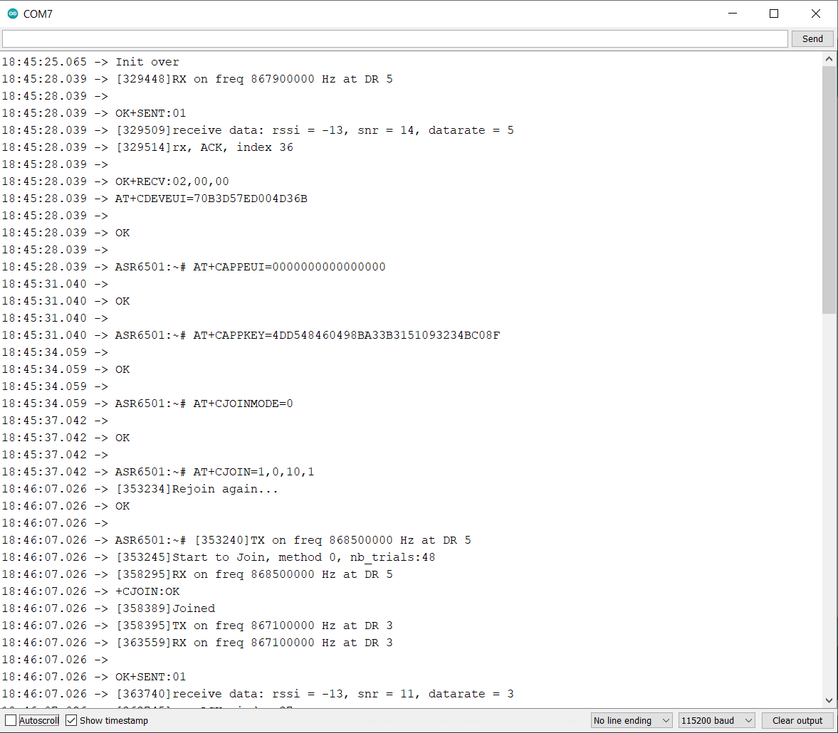
When the LoRaWAN module work in OTAA mode, the operation frequency will be automatically set to the same frequency as the matching router, if your router frequency is 868Mhz, the module will work in the 868Mhz that the LoRaWAN module support.
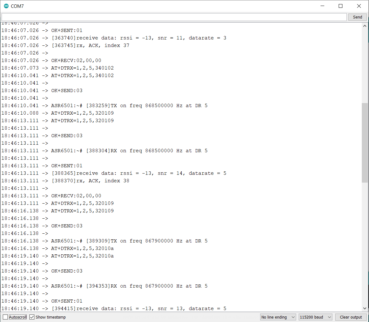
Now open the live data section on your TTN. Then wait for a minute, you can view something received in the dashboard.
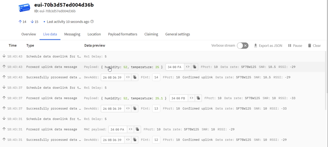
As the picture, the original payload is 3400FA, and the date after the format decoded is 52 and 25, which means the temperature is 25℃ and humidity is 52%.
This is how you can use Maduino Ra-07 LoRaWAN Module with The Things Network Server and monitor the sensor data wirelessly.
 & Live Dashboard")


2 Comments
Hello. There is something I don’t understand. There is also a processor in the RA-07 module. (MCU: ASR6502 + Lorawan: SX1262). Why is a second processor needed? A similar module, Heltec CubeCell – Dev-Board” also does not use a processor.( https://heltec.org/project/htcc-ab01/)
I love the projects here. You publish the whole project from end to end. If possible, I have a request from you. Can you also make a project example to be used only with the internal processor (ASR6501 ) in RA-7 and opensource chirpstack lorawan server? (For example, rs485 data can be transferred.) Thus, we get rid of an extra processor cost. We also gain experience in using opensource chirpstack lorawan server.