

Overview
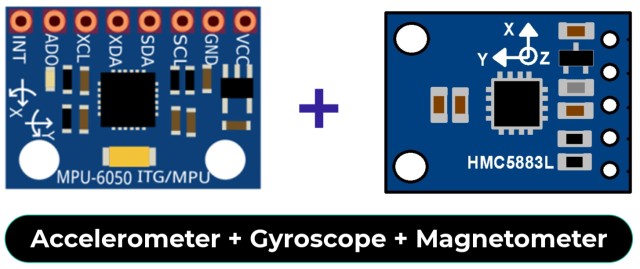
In this article, we will learn how to use ESP32 to measure 3D orientation angles – Pitch, Roll, and Yaw, using the MPU6050 Accelerometer Gyroscope and HMC5883L Magnetometer. These sensors will be interfaced with an ESP32 microcontroller, which will process the raw sensor data and calculate the orientation angles using sensor fusion techniques. This project is ideal for applications like drones, robotics, and navigation systems that require precise orientation tracking.
The MPU6050 combines a 3-axis accelerometer and 3-axis gyroscope, making it capable of detecting angular velocity and linear acceleration. However, due to the gyroscope’s drift and the accelerometer’s susceptibility to noise, we will also integrate the HMC5883L, a 3-axis magnetometer, to enhance accuracy by providing reliable yaw measurements.
By combining the data from all these sensors using a Kalman filter, we will achieve stable and precise angle measurements. The resulting values will be displayed in real time, allowing us to understand the object’s orientation in three-dimensional space. For high accuracy pitch roll yaw measurement, you can use BNO08x Accelerometer, Gyroscope, Magnetometer module.
Components Required
We need following components for Pitch, Roll, Yaw calculations. You can purchase all the components from the given links.
| S.N. | Components Name | Quantity | Purchase Link |
|---|---|---|---|
| 1 | ESP32 Board | 1 | Amazon | AliExpress | SunFounder |
| 2 | MPU6050 Gyroscope/Accelerometer | 1 | Amazon | AliExpress | SunFounder |
| 3 | HMC5883L Magnetometer | 1 | Amazon | AliExpress | SunFounder |
| 4 | OLED Display | Amazon | AliExpress | SunFounder | |
| 5 | Connecting Wires | 10 | Amazon | AliExpress | SunFounder |
| 6 | Breadboard | 2 | Amazon | AliExpress | SunFounder |
What is Pitch, Roll & Yaw?
Pitch, Roll, and Yaw are terms used to describe the orientation or rotation of an object in three-dimensional space. These angles represent rotations around the principal axes of an object: X, Y, and Z.
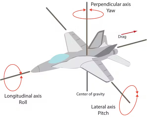
Pitch
Pitch refers to the rotation of an object about its X-axis, which results in a forward or backward tilt. It describes whether the object is tilting upward or downward.
For example, when an airplane’s nose rises or dips, it experiences pitch. A positive pitch occurs when the nose tilts upward, while a negative pitch occurs when the nose tilts downward.
Roll
Roll is the rotation of an object about its Y-axis, causing it to tilt side-to-side. This describes whether the object is tilting to the left or right.
For instance, when a plane banks to one side during a turn, it undergoes roll. A positive roll means the plane’s right wing dips down, while a negative roll means the left wing dips down.
Yaw
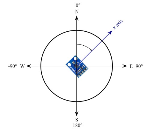
Yaw refers to the rotation of an object about its Z-axis, which results in a left or right turn. It describes the direction the object is facing or turning horizontally.
For example, when a car or drone changes its direction to the left or right, it experiences yaw. A positive yaw indicates a clockwise turn (to the right), while a negative yaw indicates a counterclockwise turn (to the left).
MPU6050 Gyroscope Accelerometer

The MPU6050 is a 6-axis MEMS motion-tracking device that combines a 3-axis accelerometer and a 3-axis gyroscope on a single chip. It operates over the I2C communication protocols and supports a configurable output data rate (ODR) up to 1 kHz.
The accelerometer measures linear acceleration along the X, Y, and Z axes, while the gyroscope detects angular velocity (rotational speed) around the same axes. Together, these sensors provide raw data to calculate angles like pitch and roll.

- Accelerometer: Measures linear acceleration along the X, Y, and Z axes, with selectable sensitivity ranges of ±2g, ±4g, ±8g, and ±16g.
- Gyroscope: Measures angular velocity around the X, Y, and Z axes, with selectable sensitivity ranges of ±250°/s, ±500°/s, ±1000°/s, and ±2000°/s.
- Resolution: Both accelerometer and gyroscope data are output as 16-bit signed integers.
- Power Supply: Operates at a voltage range of 2.375V to 3.46V with low power consumption.
- Digital Motion Processor (DMP): Features an integrated DMP for sensor fusion, enabling the computation of motion data like pitch, roll, and yaw directly on the chip.
The MPU6050 is widely used for applications requiring real-time motion tracking and orientation due to its high precision and ease of integration with microcontrollers.
You may follow previous MPU6050 related tutorials for better understanding:
- Interfacing MPU6050 Accelerometer & Gyroscope with Arduino
- Measure Tilt Angle Using MPU6050 Gyro/Accelerometer & Arduino
HMC5883L Magnetometer
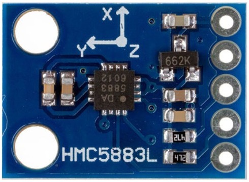
The HMC5883L is a high-performance 3-axis magnetometer designed for precision magnetic field sensing and orientation detection. It operates over the I2C communication protocol and supports data output rates (ODR) up to 75 Hz.
The HMC5883L measures the strength and direction of magnetic fields along the X, Y, and Z axes, enabling accurate heading (yaw) calculation when combined with accelerometer and gyroscope data. Its onboard circuitry provides signal conditioning and precise calibration for reliable magnetic field measurements.
- Magnetometer: Measures magnetic field strength along the X, Y, and Z axes with a full-scale range of ±1.3 Gauss to ±8.1 Gauss.
- Resolution: Outputs magnetic field data as 16-bit signed integers with a sensitivity of 0.92 mG/LSB for the default ±1.3 Gauss range.
- Output Data Rate (ODR): Configurable ODR from 0.75 Hz to 75 Hz, suitable for a wide range of applications.
- Power Supply: Operates at a voltage range of 2.16V to 3.6V, ensuring low power consumption.
The HMC5883L is commonly used in electronic compasses, navigation systems, and orientation detection due to its high precision and ease of interfacing with microcontrollers.
You may follow previous HMC5883L related tutorials for a better understanding:
- Digital Compass using HMC5883L Magnetometer & Arduino
- Interfacing HMC5883L Magnetometer with Raspberry Pi
Sensor Fusion (MPU6050 + HMC5883L)
Sensor fusion is important when calculating pitch, roll, and yaw using the MPU6050 and HMC5883L because each sensor has its strengths and weaknesses.
 The MPU6050’s accelerometer measures tilt (pitch and roll) based on gravity, but it can be affected by vibrations and sudden movements, which introduce noise. Its gyroscope measures how quickly something is rotating (angular velocity) and is great for detecting quick changes in orientation. However, over time, the gyroscope readings can drift, causing inaccuracies in the calculated angles.
The HMC5883L magnetometer helps measure yaw (the direction an object is facing) by detecting the Earth’s magnetic field. While it’s good for providing a reference direction, it can be influenced by nearby magnetic interference from electronic devices or metal objects. This can lead to incorrect yaw readings if used on its own.
Sensor fusion combines the strengths of these sensors to overcome their individual weaknesses. The gyroscope adds stability to the accelerometer readings, reducing noise and making pitch and roll calculations more accurate. At the same time, the accelerometer acts as a long-term reference to correct gyroscope drift. For yaw, the magnetometer provides the main directional reference, while the gyroscope smooths out short-term changes and helps in areas where the magnetometer might face interference.
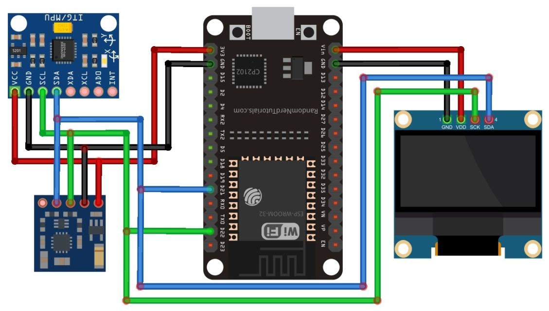
Interfacing MPU6050 + HMC5883L with ESP32
Now let us interface the MPU6050 Gyroscope Accelerometer and HMC5883L Magnetometer with ESP32 to calculate Pitch, Roll, and Yaw. Here is the hardware connection.
Since both the MPU6050 and HMC5883L are I2C modules, they can share the same I2C pins on the ESP32.
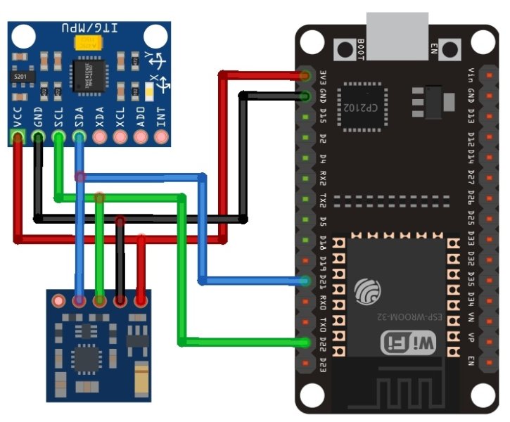
- MPU6050 Connections:
- VCC → ESP32 3.3V
- GND → ESP32 GND
- SCL → ESP32 GPIO 22 (I2C SCL)
- SDA → ESP32 GPIO 21 (I2C SDA)
- HMC5883L Connections:
- VCC → ESP32 3.3V
- GND → ESP32 GND
- SCL → ESP32 GPIO 22 (I2C SCL) (shared with MPU6050)
- SDA → ESP32 GPIO 21 (I2C SDA) (shared with MPU6050)
Both modules are powered by the 3.3V pin of the ESP32, and their I2C lines are connected in parallel to the same SCL and SDA pins.

Once the hardware is set up, you can proceed with coding to read data from both sensors and calculate orientation.
Code: Measure Pitch, Roll, Yaw with MPU6050 + HMC5883L
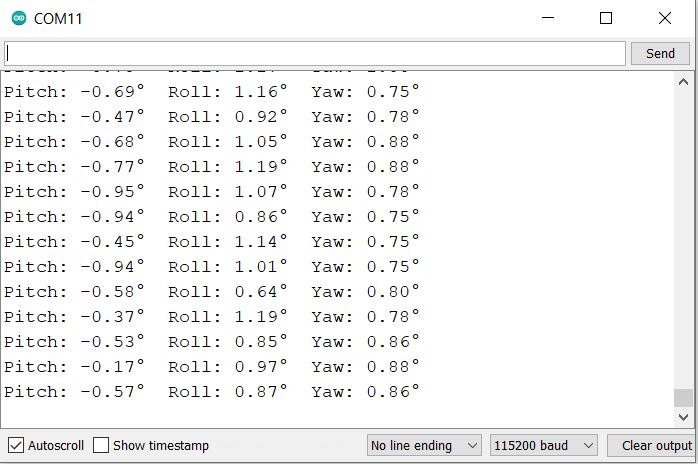
Here is the code to interface the MPU6050 Accelerometer/Gyroscope and HMC5883L Magnetometer with an ESP32 to measure pitch, roll, and yaw angles.
This code calculates pitch and roll angles using data from the accelerometer and yaw using data from the magnetometer. It also adjusts the yaw reading to account for magnetic declination, ensuring it aligns with true north. The yaw value is normalized to stay within 0 to 360 degrees for easy interpretation.
After processing, the calculated angles are displayed on the serial monitor in real time. Calibration steps are included to improve accuracy by correcting sensor offsets and reducing the impact of environmental interference.
In the below code, you need to adjust the yaw using a declination angle. Replace this angle with your location values.
|
1 2 |
// Adjust yaw using declination angle (replace with your location's value) float declinationAngle = -0.1783; // Declination in radians for -10° 13' |
To get the declination angle of your location, you may use the website magnetic-declination.com.
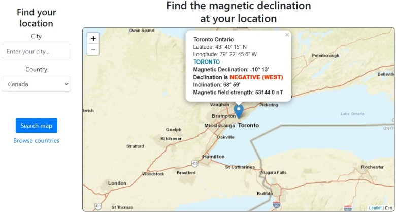
From here you will get the Magnetic Declination in degrees. You need to convert it into radians. Replace the value in the above line of the code.
Here is the final code to calculate and measure pitch, roll, and yaw using MPU6050, HMC5883L, and ESP32.
|
1 2 3 4 5 6 7 8 9 10 11 12 13 14 15 16 17 18 19 20 21 22 23 24 25 26 27 28 29 30 31 32 33 34 35 36 37 38 39 40 41 42 43 44 45 46 47 48 49 50 51 52 53 54 55 56 57 58 59 60 61 62 63 64 65 66 67 68 69 70 71 72 73 74 75 76 77 78 79 80 81 82 83 84 85 86 87 88 89 90 91 92 93 94 95 96 97 98 99 100 101 102 103 104 105 106 107 108 109 110 111 112 113 114 115 116 117 118 119 120 121 122 123 124 125 126 127 128 129 130 131 132 133 134 135 136 137 138 139 140 141 142 143 144 145 146 147 148 149 150 151 152 153 154 155 156 157 158 159 160 161 162 163 164 |
#include <Wire.h> // MPU6050 I2C address #define MPU6050_ADDR 0x68 // MPU6050 registers #define MPU6050_REG_ACCEL_XOUT_H 0x3B #define MPU6050_REG_PWR_MGMT_1 0x6B // HMC5883L I2C address #define HMC5883L_ADDR 0x1E // Sensitivity scales #define ACCEL_SCALE 16384.0 #define MAG_SCALE 0.92 // 0.92 microTesla per LSB for ±1.3 Gauss // Calibration offsets double accelOffsetX = 0, accelOffsetY = 0, accelOffsetZ = 0; double magMinX = 0, magMaxX = 0, magMinY = 0, magMaxY = 0, magMinZ = 0, magMaxZ = 0; void setup() { Serial.begin(115200); Wire.begin(); // Initialize I2C MPU6050_init(); // Initialize MPU6050 HMC5883L_init(); // Initialize HMC5883L calibrate_MPU6050(); // Calibrate accelerometer calibrate_HMC5883L(); // Calibrate magnetometer } void loop() { double ax, ay, az; double mx, my, mz; double pitch, roll, yaw; // Read MPU6050 accelerometer data read_MPU6050(ax, ay, az); // Calculate pitch and roll pitch = atan2(-ax, sqrt(ay * ay + az * az)) * 180.0 / PI; roll = atan2(ay, az) * 180.0 / PI; // Read HMC5883L magnetometer data read_HMC5883L(mx, my, mz); // Calculate yaw from magnetometer data yaw = atan2(my, mx); // Adjust yaw using declination angle (replace with your location's value) float declinationAngle = -0.1783; // Declination in radians for -10° 13' yaw += declinationAngle; // Normalize yaw to 0-360 degrees if (yaw < 0) yaw += 2 * PI; if (yaw > 2 * PI) yaw -= 2 * PI; yaw = yaw * 180.0 / PI; // Convert to degrees // Print results Serial.print("Pitch: "); Serial.print(pitch); Serial.print("° "); Serial.print("Roll: "); Serial.print(roll); Serial.print("° "); Serial.print("Yaw: "); Serial.print(yaw); Serial.println("°"); delay(200); } void MPU6050_init() { Wire.beginTransmission(MPU6050_ADDR); Wire.write(MPU6050_REG_PWR_MGMT_1); Wire.write(0); // Wake up MPU6050 Wire.endTransmission(true); } void calibrate_MPU6050() { Serial.println("Calibrating MPU6050..."); double ax, ay, az; int numSamples = 100; for (int i = 0; i < numSamples; i++) { read_MPU6050(ax, ay, az); accelOffsetX += ax; accelOffsetY += ay; accelOffsetZ += az; delay(10); } accelOffsetX /= numSamples; accelOffsetY /= numSamples; accelOffsetZ /= numSamples; // Assuming Z points up, adjust for gravity accelOffsetZ -= 1.0; // Gravity in g (9.8 m/s^2) Serial.println("MPU6050 Calibration Complete."); } void read_MPU6050(double &ax, double &ay, double &az) { Wire.beginTransmission(MPU6050_ADDR); Wire.write(MPU6050_REG_ACCEL_XOUT_H); // Starting register for Accel Readings Wire.endTransmission(false); Wire.requestFrom(MPU6050_ADDR, 6, true); ax = (Wire.read() << 8 | Wire.read()) / ACCEL_SCALE - accelOffsetX; ay = (Wire.read() << 8 | Wire.read()) / ACCEL_SCALE - accelOffsetY; az = (Wire.read() << 8 | Wire.read()) / ACCEL_SCALE - accelOffsetZ; } void HMC5883L_init() { Wire.beginTransmission(HMC5883L_ADDR); Wire.write(0x00); // Configuration Register A Wire.write(0x70); // 8-average, 15 Hz default, normal measurement Wire.endTransmission(); Wire.beginTransmission(HMC5883L_ADDR); Wire.write(0x01); // Configuration Register B Wire.write(0x20); // Gain = 5 (±1.3 Gauss) Wire.endTransmission(); Wire.beginTransmission(HMC5883L_ADDR); Wire.write(0x02); // Mode Register Wire.write(0x00); // Continuous measurement mode Wire.endTransmission(); } void calibrate_HMC5883L() { Serial.println("Calibrating HMC5883L..."); double mx, my, mz; magMinX = magMinY = magMinZ = 1e6; magMaxX = magMaxY = magMaxZ = -1e6; unsigned long startTime = millis(); while (millis() - startTime < 10000) { // 10 seconds for calibration read_HMC5883L(mx, my, mz); if (mx < magMinX) magMinX = mx; if (mx > magMaxX) magMaxX = mx; if (my < magMinY) magMinY = my; if (my > magMaxY) magMaxY = my; if (mz < magMinZ) magMinZ = mz; if (mz > magMaxZ) magMaxZ = mz; delay(100); } Serial.println("HMC5883L Calibration Complete."); } void read_HMC5883L(double &mx, double &my, double &mz) { Wire.beginTransmission(HMC5883L_ADDR); Wire.write(0x03); // Starting register for magnetometer readings Wire.endTransmission(false); Wire.requestFrom(HMC5883L_ADDR, 6, true); int16_t x = Wire.read() << 8 | Wire.read(); int16_t z = Wire.read() << 8 | Wire.read(); int16_t y = Wire.read() << 8 | Wire.read(); // Apply calibration offsets and scaling mx = (x - (magMinX + magMaxX) / 2) * MAG_SCALE; my = (y - (magMinY + magMaxY) / 2) * MAG_SCALE; mz = (z - (magMinZ + magMaxZ) / 2) * MAG_SCALE; } |
Upload the above code to the ESP32 Board. Once the code is uploaded you need to start the testing. The code has a calibration part. Hence a small step is needed for calibration.
For the MPU6050, keep the sensor stationary during calibration to ensure accurate offset values. For the HMC5883L, rotate the sensor in all directions during calibration to capture the full range of magnetic field values.
After calibration, test the pitch, roll, and yaw outputs:
- Hold the sensor stationary and check if the pitch and roll are close to zero when level.
- Gradually tilt the sensor and confirm that pitch and roll values change consistently with the movement.
- Rotate the sensor horizontally and ensure the yaw value changes smoothly from 0 to 360 degrees.
Measure Pitch, Roll, and Yaw Accurately with the Kalman Filter
The accelerometer is good for determining long-term tilt angles (pitch and roll) based on gravity but is noisy and affected by vibrations. The gyroscope provides precise angular velocity for detecting short-term changes but suffers from drift over time, leading to cumulative errors. Similarly, the magnetometer gives absolute yaw (heading) but is sensitive to magnetic interference.
A Kalman filter is used to improve the accuracy of pitch, roll, and yaw measurements by combining data from multiple sensors (like accelerometers, gyroscopes, and magnetometers) while accounting for their individual limitations. The Kalman filter fuses this data intelligently to produce smoother and more reliable orientation readings.
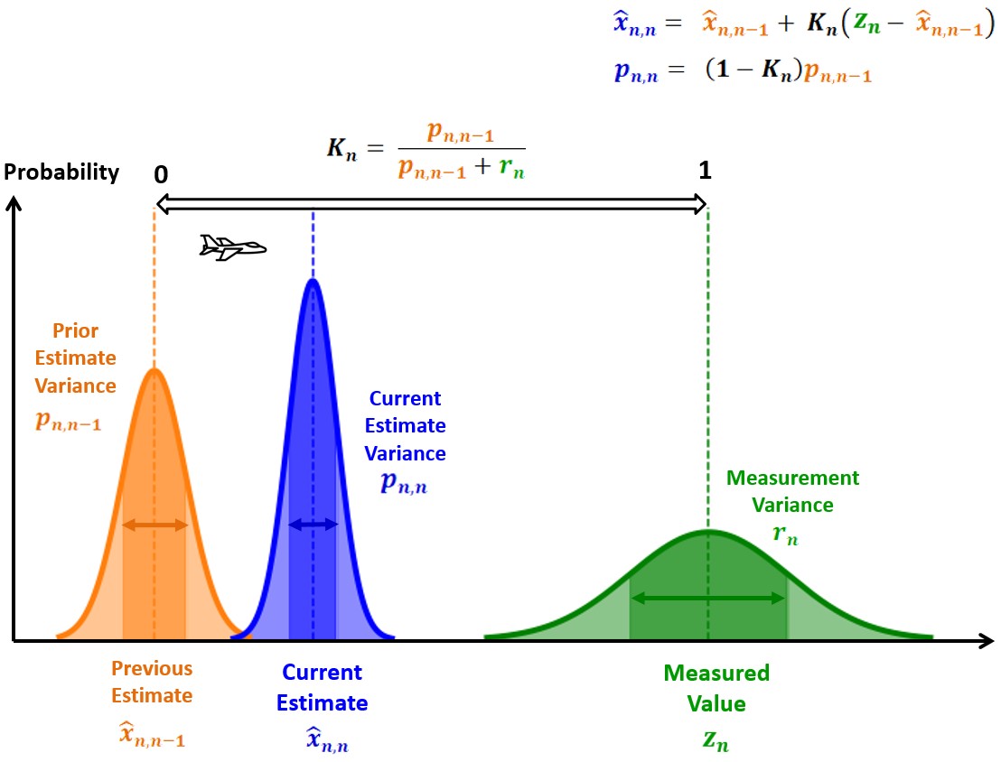
The Kalman filter uses a mathematical model to predict the orientation based on gyroscope data and then corrects it using accelerometer and magnetometer readings. This process improves the overall accuracy and stability of pitch, roll, and yaw measurements.
Code: Pitch, Roll, Yaw with the Kalman Filter Implementation
The code uses a Kalman filter to combine data from the gyroscope and accelerometer for calculating pitch and roll. This fusion helps produce smoother and more accurate angle measurements by reducing noise from the accelerometer and correcting for drift in the gyroscope over time. For yaw, the code uses magnetometer data and adjusts it with a magnetic declination angle to ensure the heading aligns with true north.
The yaw angle is further normalized to stay within a range of 0 to 360 degrees, making the output easier to interpret. Finally, all calculated angles—pitch, roll, and yaw—are displayed in real-time on the serial monitor for monitoring and validation.
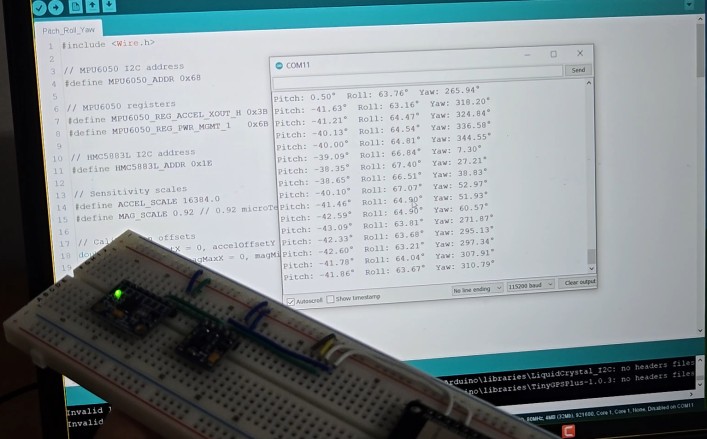
Here is the final code for the ESP32 Microcontroller fused with MPU6050 and HMC5883L along with the implementation of Kalman Filter to measure Pitch, Roll, and Yaw more accurately and precisely.
|
1 2 3 4 5 6 7 8 9 10 11 12 13 14 15 16 17 18 19 20 21 22 23 24 25 26 27 28 29 30 31 32 33 34 35 36 37 38 39 40 41 42 43 44 45 46 47 48 49 50 51 52 53 54 55 56 57 58 59 60 61 62 63 64 65 66 67 68 69 70 71 72 73 74 75 76 77 78 79 80 81 82 83 84 85 86 87 88 89 90 91 92 93 94 95 96 97 98 99 100 101 102 103 104 105 106 107 108 109 110 111 112 113 114 115 116 117 118 119 120 121 122 123 124 125 126 127 128 129 130 131 132 133 134 135 136 137 138 139 140 141 142 143 144 145 146 147 148 149 150 151 152 153 154 155 156 157 158 159 160 161 162 163 164 165 166 167 168 169 170 171 172 173 174 175 176 177 178 179 180 181 182 183 184 185 186 187 188 189 190 191 192 193 194 195 196 197 198 199 200 201 202 203 204 205 206 207 208 209 210 211 212 213 214 215 216 217 218 219 220 221 222 223 224 225 226 227 |
#include <Wire.h> // --- DEVICE ADDRESSES --- #define MPU6050_ADDR 0x68 // MPU6050 I2C address #define HMC5883L_ADDR 0x1E // HMC5883L I2C address // --- MPU6050 REGISTERS --- #define MPU6050_REG_ACCEL_XOUT_H 0x3B // Starting register for accelerometer readings #define MPU6050_REG_PWR_MGMT_1 0x6B // Power management register #define MPU6050_REG_GYRO_XOUT_H 0x43 // Starting register for gyroscope readings // --- SENSITIVITY SCALES --- #define ACCEL_SCALE 16384.0 // Accelerometer scale for ±2g (16-bit) #define GYRO_SCALE 131.0 // Gyroscope scale for ±250°/s (16-bit) #define MAG_SCALE 0.92 // Magnetometer scale for ±1.3 Gauss // --- CALIBRATION OFFSETS --- double accelOffsetX = 0, accelOffsetY = 0, accelOffsetZ = 0; // Accelerometer offsets double gyroXOffset = 0, gyroYOffset = 0, gyroZOffset = 0; // Gyroscope offsets double magMinX = 0, magMaxX = 0, magMinY = 0, magMaxY = 0, magMinZ = 0, magMaxZ = 0; // Magnetometer calibration // --- FILTER VARIABLES --- double pitch = 0, roll = 0, yaw = 0; // Orientation angles (degrees) double dt = 0.02; // Loop time in seconds (50 Hz) // --- KALMAN FILTER PARAMETERS --- double Q_angle = 0.001; // Process noise variance for the accelerometer double Q_bias = 0.003; // Process noise variance for the gyroscope bias double R_measure = 0.03; // Measurement noise variance double angle = 0, bias = 0, rate = 0; // Kalman filter state variables double P[2][2] = {{0, 0}, {0, 0}}; // Error covariance matrix unsigned long lastTime; // For calculating loop time void setup() { // --- INITIAL SETUP --- Serial.begin(115200); // Initialize serial communication for debugging Wire.begin(); // Initialize I2C communication // --- SENSOR INITIALIZATION --- MPU6050_init(); // Initialize MPU6050 HMC5883L_init(); // Initialize HMC5883L // --- SENSOR CALIBRATION --- calibrate_MPU6050(); // Calibrate accelerometer and gyroscope calibrate_HMC5883L(); // Calibrate magnetometer lastTime = millis(); // Set the initial time for the loop } void loop() { double ax, ay, az, gx, gy, gz; // Variables to store accelerometer and gyroscope data double mx, my, mz; // Variables to store magnetometer data // --- READ SENSOR DATA --- read_MPU6050(ax, ay, az, gx, gy, gz); // Get accelerometer and gyroscope data read_HMC5883L(mx, my, mz); // Get magnetometer data // --- CALCULATE TIME STEP --- unsigned long currentTime = millis(); dt = (currentTime - lastTime) / 1000.0; // Calculate time in seconds if (dt == 0) dt = 0.001; // Prevent division by zero lastTime = currentTime; // --- KALMAN FILTER FOR PITCH AND ROLL --- pitch = Kalman_filter(pitch, gx, atan2(-ax, sqrt(ay * ay + az * az)) * 180.0 / PI); roll = Kalman_filter(roll, gy, atan2(ay, az) * 180.0 / PI); // --- YAW CALCULATION USING MAGNETOMETER --- yaw = atan2(my, mx); // Calculate yaw from magnetometer readings float declinationAngle = -0.1783; // Declination in radians for -10° 13' yaw += declinationAngle; // Adjust for magnetic declination // Normalize yaw to 0-360 degrees if (yaw < 0) yaw += 2 * PI; if (yaw > 2 * PI) yaw -= 2 * PI; yaw = yaw * 180.0 / PI; // Convert yaw to degrees // --- PRINT RESULTS --- Serial.print("Pitch: "); Serial.print(pitch); Serial.print("° "); Serial.print("Roll: "); Serial.print(roll); Serial.print("° "); Serial.print("Yaw: "); Serial.print(yaw); Serial.println("°"); delay(20); // Maintain 50 Hz loop frequency } // --- SENSOR INITIALIZATION FUNCTIONS --- void MPU6050_init() { Wire.beginTransmission(MPU6050_ADDR); Wire.write(MPU6050_REG_PWR_MGMT_1); // Select power management register Wire.write(0); // Wake up MPU6050 Wire.endTransmission(true); } void HMC5883L_init() { Wire.beginTransmission(HMC5883L_ADDR); Wire.write(0x00); // Configuration Register A Wire.write(0x70); // 8-average, 15 Hz default, normal measurement Wire.endTransmission(); Wire.beginTransmission(HMC5883L_ADDR); Wire.write(0x01); // Configuration Register B Wire.write(0x20); // Gain = 5 (±1.3 Gauss) Wire.endTransmission(); Wire.beginTransmission(HMC5883L_ADDR); Wire.write(0x02); // Mode Register Wire.write(0x00); // Continuous measurement mode Wire.endTransmission(); } // --- SENSOR CALIBRATION FUNCTIONS --- void calibrate_MPU6050() { Serial.println("Calibrating MPU6050..."); double ax, ay, az, gx, gy, gz; int numSamples = 100; for (int i = 0; i < numSamples; i++) { read_MPU6050(ax, ay, az, gx, gy, gz); accelOffsetX += ax; accelOffsetY += ay; accelOffsetZ += az; gyroXOffset += gx; gyroYOffset += gy; gyroZOffset += gz; delay(10); } accelOffsetX /= numSamples; accelOffsetY /= numSamples; accelOffsetZ /= numSamples; gyroXOffset /= numSamples; gyroYOffset /= numSamples; gyroZOffset /= numSamples; // Adjust for gravity on the Z-axis accelOffsetZ -= 1.0; Serial.println("MPU6050 Calibration Complete."); } void calibrate_HMC5883L() { Serial.println("Calibrating HMC5883L... Rotate the sensor in all directions."); double mx, my, mz; magMinX = magMinY = magMinZ = 1e6; magMaxX = magMaxY = magMaxZ = -1e6; unsigned long startTime = millis(); while (millis() - startTime < 10000) { // 10 seconds for calibration read_HMC5883L(mx, my, mz); if (mx < magMinX) magMinX = mx; if (mx > magMaxX) magMaxX = mx; if (my < magMinY) magMinY = my; if (my > magMaxY) magMaxY = my; if (mz < magMinZ) magMinZ = mz; if (mz > magMaxZ) magMaxZ = mz; Serial.print("."); // Print a dot every 100 ms to indicate progress delay(100); } Serial.println("\nHMC5883L Calibration Complete."); } // --- SENSOR READING FUNCTIONS --- void read_MPU6050(double &ax, double &ay, double &az, double &gx, double &gy, double &gz) { Wire.beginTransmission(MPU6050_ADDR); Wire.write(MPU6050_REG_ACCEL_XOUT_H); // Starting register for Accel Readings Wire.endTransmission(false); Wire.requestFrom(MPU6050_ADDR, 14, true); ax = (Wire.read() << 8 | Wire.read()) / ACCEL_SCALE - accelOffsetX; ay = (Wire.read() << 8 | Wire.read()) / ACCEL_SCALE - accelOffsetY; az = (Wire.read() << 8 | Wire.read()) / ACCEL_SCALE - accelOffsetZ; gx = (Wire.read() << 8 | Wire.read()) / GYRO_SCALE - gyroXOffset; gy = (Wire.read() << 8 | Wire.read()) / GYRO_SCALE - gyroYOffset; gz = (Wire.read() << 8 | Wire.read()) / GYRO_SCALE - gyroZOffset; } void read_HMC5883L(double &mx, double &my, double &mz) { Wire.beginTransmission(HMC5883L_ADDR); Wire.write(0x03); // Starting register for magnetometer readings Wire.endTransmission(false); Wire.requestFrom(HMC5883L_ADDR, 6, true); int16_t x = Wire.read() << 8 | Wire.read(); int16_t z = Wire.read() << 8 | Wire.read(); int16_t y = Wire.read() << 8 | Wire.read(); // Apply calibration offsets and scaling mx = (x - (magMinX + magMaxX) / 2) * MAG_SCALE; my = (y - (magMinY + magMaxY) / 2) * MAG_SCALE; mz = (z - (magMinZ + magMaxZ) / 2) * MAG_SCALE; } // --- KALMAN FILTER FUNCTION --- double Kalman_filter(double angle, double gyroRate, double accelAngle) { // Predict rate = gyroRate - bias; angle += dt * rate; P[0][0] += dt * (dt * P[1][1] - P[0][1] - P[1][0] + Q_angle); P[0][1] -= dt * P[1][1]; P[1][0] -= dt * P[1][1]; P[1][1] += Q_bias * dt; // Update double S = P[0][0] + R_measure; // Estimate error double K[2]; // Kalman gain K[0] = P[0][0] / S; K[1] = P[1][0] / S; double y = accelAngle - angle; // Angle difference angle += K[0] * y; bias += K[1] * y; double P00_temp = P[0][0]; double P01_temp = P[0][1]; P[0][0] -= K[0] * P00_temp; P[0][1] -= K[0] * P01_temp; P[1][0] -= K[1] * P00_temp; P[1][1] -= K[1] * P01_temp; return angle; } |
Upload the above code to the ESP32 Board and open the Serial Monitor. The Serial Monitor will print 3D angle as Pitch, Roll, Yaw more accurately using the MPU6050 and HMC5883L.
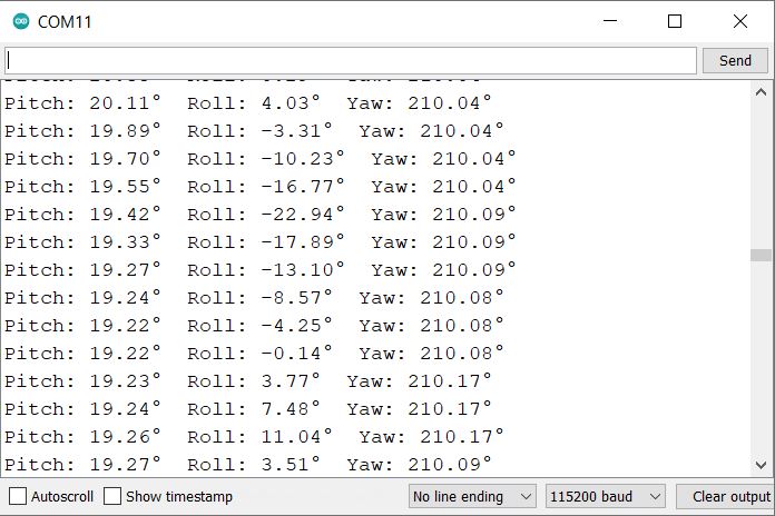
Displaying MPU6050 + HMC5883L Pitch Roll Yaw Values on OLED Display
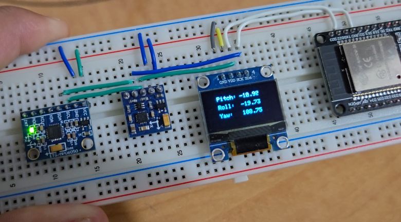
To make testing more visual, connect an OLED to the ESP32 and display pitch, roll, and yaw values directly on the screen. This makes debugging easier and provides a real-time interface.
You can use a 0.96″ SSD1306 OLED Display with ESP32. It has an I2C Pin hence you can connect it in parallel with MPU6050 and HMC5883L Pins.
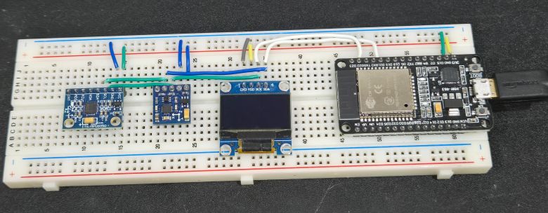
It’s easier to put everything on the breadboard as shown below.
Upload the code below to the ESP32 board to display Pitch, Roll, and Yaw values on the OLED screen.
|
1 2 3 4 5 6 7 8 9 10 11 12 13 14 15 16 17 18 19 20 21 22 23 24 25 26 27 28 29 30 31 32 33 34 35 36 37 38 39 40 41 42 43 44 45 46 47 48 49 50 51 52 53 54 55 56 57 58 59 60 61 62 63 64 65 66 67 68 69 70 71 72 73 74 75 76 77 78 79 80 81 82 83 84 85 86 87 88 89 90 91 92 93 94 95 96 97 98 99 100 101 102 103 104 105 106 107 108 109 110 111 112 113 114 115 116 117 118 119 120 121 122 123 124 125 126 127 128 129 130 131 132 133 134 135 136 137 138 139 140 141 142 143 144 145 146 147 148 149 150 151 152 153 154 155 156 157 158 159 160 161 162 163 164 165 166 167 168 169 170 171 172 173 174 175 176 177 178 179 180 181 182 183 184 185 186 187 188 189 190 191 192 193 194 195 196 197 198 199 200 201 202 203 204 205 206 207 208 209 210 211 212 213 214 215 216 217 218 219 220 221 222 223 224 225 226 227 228 229 230 231 232 233 234 235 236 237 238 239 240 241 242 243 244 245 246 247 248 249 250 251 252 253 254 255 256 257 258 259 260 261 262 |
#include <Wire.h> #include <Adafruit_GFX.h> #include <Adafruit_SSD1306.h> #define SCREEN_WIDTH 128 #define SCREEN_HEIGHT 64 #define OLED_RESET -1 Adafruit_SSD1306 display(SCREEN_WIDTH, SCREEN_HEIGHT, &Wire, OLED_RESET); // --- DEVICE ADDRESSES --- #define MPU6050_ADDR 0x68 // MPU6050 I2C address #define HMC5883L_ADDR 0x1E // HMC5883L I2C address // --- MPU6050 REGISTERS --- #define MPU6050_REG_ACCEL_XOUT_H 0x3B // Starting register for accelerometer readings #define MPU6050_REG_PWR_MGMT_1 0x6B // Power management register #define MPU6050_REG_GYRO_XOUT_H 0x43 // Starting register for gyroscope readings // --- SENSITIVITY SCALES --- #define ACCEL_SCALE 16384.0 // Accelerometer scale for ±2g (16-bit) #define GYRO_SCALE 131.0 // Gyroscope scale for ±250°/s (16-bit) #define MAG_SCALE 0.92 // Magnetometer scale for ±1.3 Gauss // --- CALIBRATION OFFSETS --- double accelOffsetX = 0, accelOffsetY = 0, accelOffsetZ = 0; // Accelerometer offsets double gyroXOffset = 0, gyroYOffset = 0, gyroZOffset = 0; // Gyroscope offsets double magMinX = 0, magMaxX = 0, magMinY = 0, magMaxY = 0, magMinZ = 0, magMaxZ = 0; // Magnetometer calibration // --- FILTER VARIABLES --- double pitch = 0, roll = 0, yaw = 0; // Orientation angles (degrees) double dt = 0.02; // Loop time in seconds (50 Hz) // --- KALMAN FILTER PARAMETERS --- double Q_angle = 0.001; // Process noise variance for the accelerometer double Q_bias = 0.003; // Process noise variance for the gyroscope bias double R_measure = 0.03; // Measurement noise variance double angle = 0, bias = 0, rate = 0; // Kalman filter state variables double P[2][2] = {{0, 0}, {0, 0}}; // Error covariance matrix unsigned long lastTime; // For calculating loop time void setup() { // --- INITIAL SETUP --- Serial.begin(115200); // Initialize serial communication for debugging Wire.begin(); // Initialize I2C communication // --- OLED INITIALIZATION --- display.begin(SSD1306_SWITCHCAPVCC, 0x3C); display.clearDisplay(); display.setTextColor(WHITE); // --- SENSOR INITIALIZATION --- MPU6050_init(); // Initialize MPU6050 HMC5883L_init(); // Initialize HMC5883L // --- SENSOR CALIBRATION --- calibrate_MPU6050(); // Calibrate accelerometer and gyroscope calibrate_HMC5883L(); // Calibrate magnetometer lastTime = millis(); // Set the initial time for the loop } void loop() { double ax, ay, az, gx, gy, gz; // Variables to store accelerometer and gyroscope data double mx, my, mz; // Variables to store magnetometer data // --- READ SENSOR DATA --- read_MPU6050(ax, ay, az, gx, gy, gz); // Get accelerometer and gyroscope data read_HMC5883L(mx, my, mz); // Get magnetometer data // --- CALCULATE TIME STEP --- unsigned long currentTime = millis(); dt = (currentTime - lastTime) / 1000.0; // Calculate time in seconds if (dt == 0) dt = 0.001; // Prevent division by zero lastTime = currentTime; // --- KALMAN FILTER FOR PITCH AND ROLL --- pitch = Kalman_filter(pitch, gx, atan2(-ax, sqrt(ay * ay + az * az)) * 180.0 / PI); roll = Kalman_filter(roll, gy, atan2(ay, az) * 180.0 / PI); // --- YAW CALCULATION USING MAGNETOMETER --- yaw = atan2(my, mx); // Calculate yaw from magnetometer readings float declinationAngle = -0.1783; // Declination in radians for -10° 13' yaw += declinationAngle; // Adjust for magnetic declination // Normalize yaw to 0-360 degrees if (yaw < 0) yaw += 2 * PI; if (yaw > 2 * PI) yaw -= 2 * PI; yaw = yaw * 180.0 / PI; // Convert yaw to degrees // --- PRINT RESULTS --- Serial.print("Pitch: "); Serial.print(pitch); Serial.print("° "); Serial.print("Roll: "); Serial.print(roll); Serial.print("° "); Serial.print("Yaw: "); Serial.print(yaw); Serial.println("°"); display.clearDisplay(); display.setTextSize(1); display.setCursor(20, 10); display.print("Pitch: "); display.print(pitch); display.setTextSize(1); display.setCursor(20, 25); display.print("Roll: "); display.print(roll); display.setTextSize(1); display.setCursor(20, 40); display.print("Yaw: "); display.print(yaw); display.display(); delay(20); // Maintain 50 Hz loop frequency } // --- SENSOR INITIALIZATION FUNCTIONS --- void MPU6050_init() { Wire.beginTransmission(MPU6050_ADDR); Wire.write(MPU6050_REG_PWR_MGMT_1); // Select power management register Wire.write(0); // Wake up MPU6050 Wire.endTransmission(true); } void HMC5883L_init() { Wire.beginTransmission(HMC5883L_ADDR); Wire.write(0x00); // Configuration Register A Wire.write(0x70); // 8-average, 15 Hz default, normal measurement Wire.endTransmission(); Wire.beginTransmission(HMC5883L_ADDR); Wire.write(0x01); // Configuration Register B Wire.write(0x20); // Gain = 5 (±1.3 Gauss) Wire.endTransmission(); Wire.beginTransmission(HMC5883L_ADDR); Wire.write(0x02); // Mode Register Wire.write(0x00); // Continuous measurement mode Wire.endTransmission(); } // --- SENSOR CALIBRATION FUNCTIONS --- void calibrate_MPU6050() { Serial.println("Calibrating MPU6050..."); display.setTextSize(1); display.setCursor(0, 00); display.print("Calibrating...."); display.display(); double ax, ay, az, gx, gy, gz; int numSamples = 100; for (int i = 0; i < numSamples; i++) { read_MPU6050(ax, ay, az, gx, gy, gz); accelOffsetX += ax; accelOffsetY += ay; accelOffsetZ += az; gyroXOffset += gx; gyroYOffset += gy; gyroZOffset += gz; delay(10); } accelOffsetX /= numSamples; accelOffsetY /= numSamples; accelOffsetZ /= numSamples; gyroXOffset /= numSamples; gyroYOffset /= numSamples; gyroZOffset /= numSamples; // Adjust for gravity on the Z-axis accelOffsetZ -= 1.0; Serial.println("MPU6050 Calibration Complete."); } void calibrate_HMC5883L() { Serial.println("Calibrating HMC5883L... Rotate the sensor in all directions."); double mx, my, mz; magMinX = magMinY = magMinZ = 1e6; magMaxX = magMaxY = magMaxZ = -1e6; unsigned long startTime = millis(); while (millis() - startTime < 10000) { // 10 seconds for calibration read_HMC5883L(mx, my, mz); if (mx < magMinX) magMinX = mx; if (mx > magMaxX) magMaxX = mx; if (my < magMinY) magMinY = my; if (my > magMaxY) magMaxY = my; if (mz < magMinZ) magMinZ = mz; if (mz > magMaxZ) magMaxZ = mz; Serial.print("."); // Print a dot every 100 ms to indicate progress delay(100); } Serial.println("\nHMC5883L Calibration Complete."); } // --- SENSOR READING FUNCTIONS --- void read_MPU6050(double &ax, double &ay, double &az, double &gx, double &gy, double &gz) { Wire.beginTransmission(MPU6050_ADDR); Wire.write(MPU6050_REG_ACCEL_XOUT_H); // Starting register for Accel Readings Wire.endTransmission(false); Wire.requestFrom(MPU6050_ADDR, 14, true); ax = (Wire.read() << 8 | Wire.read()) / ACCEL_SCALE - accelOffsetX; ay = (Wire.read() << 8 | Wire.read()) / ACCEL_SCALE - accelOffsetY; az = (Wire.read() << 8 | Wire.read()) / ACCEL_SCALE - accelOffsetZ; gx = (Wire.read() << 8 | Wire.read()) / GYRO_SCALE - gyroXOffset; gy = (Wire.read() << 8 | Wire.read()) / GYRO_SCALE - gyroYOffset; gz = (Wire.read() << 8 | Wire.read()) / GYRO_SCALE - gyroZOffset; } void read_HMC5883L(double &mx, double &my, double &mz) { Wire.beginTransmission(HMC5883L_ADDR); Wire.write(0x03); // Starting register for magnetometer readings Wire.endTransmission(false); Wire.requestFrom(HMC5883L_ADDR, 6, true); int16_t x = Wire.read() << 8 | Wire.read(); int16_t z = Wire.read() << 8 | Wire.read(); int16_t y = Wire.read() << 8 | Wire.read(); // Apply calibration offsets and scaling mx = (x - (magMinX + magMaxX) / 2) * MAG_SCALE; my = (y - (magMinY + magMaxY) / 2) * MAG_SCALE; mz = (z - (magMinZ + magMaxZ) / 2) * MAG_SCALE; } // --- KALMAN FILTER FUNCTION --- double Kalman_filter(double angle, double gyroRate, double accelAngle) { // Predict rate = gyroRate - bias; angle += dt * rate; P[0][0] += dt * (dt * P[1][1] - P[0][1] - P[1][0] + Q_angle); P[0][1] -= dt * P[1][1]; P[1][0] -= dt * P[1][1]; P[1][1] += Q_bias * dt; // Update double S = P[0][0] + R_measure; // Estimate error double K[2]; // Kalman gain K[0] = P[0][0] / S; K[1] = P[1][0] / S; double y = accelAngle - angle; // Angle difference angle += K[0] * y; bias += K[1] * y; double P00_temp = P[0][0]; double P01_temp = P[0][1]; P[0][0] -= K[0] * P00_temp; P[0][1] -= K[0] * P01_temp; P[1][0] -= K[1] * P00_temp; P[1][1] -= K[1] * P01_temp; return angle; } |
After uploading the code, the OLED will show the sensor is calibrating. Then it will start displaying the Pitch Roll Yaw values on the OLED Screen.
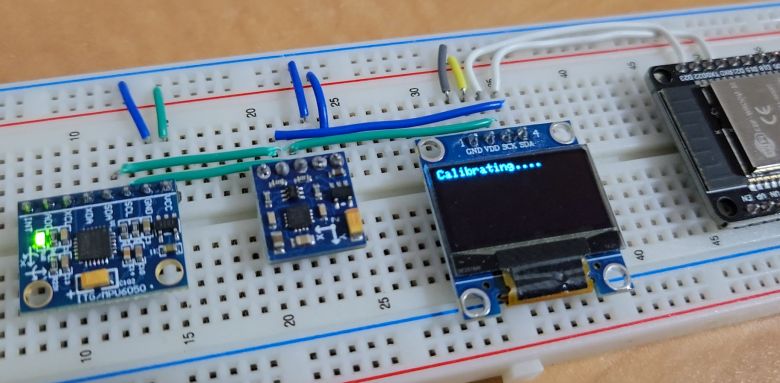
Once Calibration is done, the OLED will show Pitch, Roll, and Yaw values.
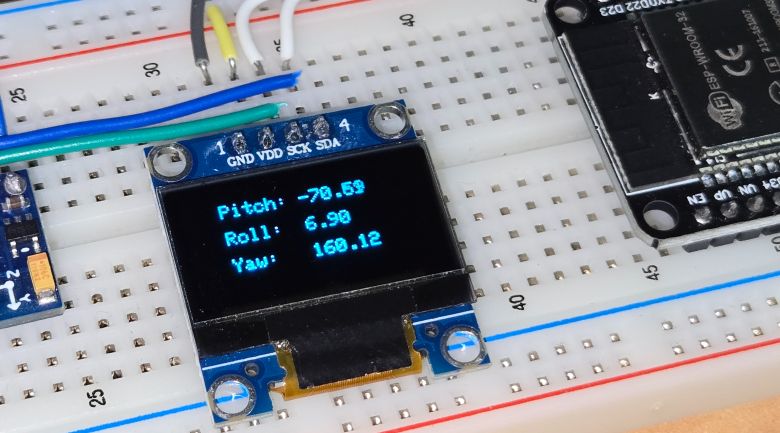
If the sensor is placed on a plane surface without moving in any direction, it shall show a very stable reading and almost the same value all the time.
To observe the change in Pitch, Roll, and Yaw values, you need to rotate or tilt the MPU6050 & HMC5883L module in any direction.
 That’s all from the tutorial part for Pitch, Roll, and Yaw measurement.
Video Tutorial & Guide

 & Live Dashboard")


1 Comment
I am just learning about this, and I found it confusing at the beginning definitions, for example when you say “Pitch refers to the rotation of an object about its X-axis,” but then show an image depicting rotation about Z with a caption “Fig: Rotation about Pitch Axis Z”.