
 Meter using BH1750 Ambient Light Sensor & Arduino")
Overview
In this project, we will make a Light Meter or Lux Meter using BH1750 Ambient Light Sensor & Arduino & display the Illuminance value in 16×2 LCD Display. Using this sensor we can calculate the amount of light in lux units. This sensor has a wide range of applications & is most suitable to obtain the ambient light data for adjusting the LCD and Keypad backlight power of the Mobile phone.
Earlier, we made Illuminance Meter using TEMT6000 Ambient Light Sensorand measured the Light Intensity. But the TEMT6000 is an analog sensor and hence slight fluctuation in voltage parameter can significantly affect the lux value. Hence BH1750 along with Arduino is a better sensor for Light Sensor application project. You can also use BH1750 with ESP8266 or ESP32 Controllers.
Bill of Materials
The components required for this project are as follows. All the components can be easily purchased from Amazon.
| S.N. | Components Name | Quantity | Purchase Links |
|---|---|---|---|
| 1 | Arduino Nano | 1 | Amazon | AliExpress |
| 2 | 16x2 LCD Display | 1 | Amazon | AliExpress |
| 3 | BH1750 Ambient Light Sensor | 1 | Amazon | AliExpress |
| 4 | Potentiometer 10K | 1 | Amazon | AliExpress |
| 5 | Connecting Jumper Wires | 10 | Amazon | AliExpress |
| 6 | Breadboard | 1 | Amazon | AliExpress |
BH1750 Ambient Light Sensor

This is a BH1750 light intensity sensor breakout board that is a digital Ambient Light Sensor IC with an I2C bus interface. This IC is best suited to get the ambient light data in mobile phones to manipulate the screen brightness based on the environment lighting. This sensor can accurately measure the LUX value of light up to 65535. It consumes a very low amount of current & uses a photodiode to sense the light.
Working of BH1750 Ambient Light Sensor
The BH1750 can be easily interfaced with Arduino or any other microcontroller. The photodiode on BH1750 detects the light intensity, which is converted as a voltage output with the help of an integration OP-AMP.
The built-in ADC finally gives out the 16-bit digital data. The internal logic of BH1750 avoids the need for any complicated calculations, as it directly outputs meaningful digital data in Lux (Lx).
BH1750 Circuit & Construction
BH1750 works with a supply voltage of 2.4V to 3.6V. BH1750FVI is the main module of the sensor which requires 3.3V for working. So, a voltage regulator is used in the circuit. SDA and SCL are the pins used for I2C communication. 4.7kΩ of pullup resistors are used with these pins.

The address of the device depends on the logic state of the address pin. There is an onboard pull down on the address pin, so with no connection, it defaults to the low address (0x23). PCB jumper (J1) allows easy configuration of the address pin; if J1 is closed the address pin will be pulled high, and the address will be 0x5C. The address of the module can also be controlled over the input signal on the ADD pin, keeping the jumper(J1) open. The DVI pin has an RC delay on it, delaying it enough to allow a proper power-on reset. The I2C interface, address, and DVI pins are brought out on a breadboard compatible berg strip, which makes it easy to use with your Arduino or any other microcontroller.
Measurement Modes
BH1705 has 3 measurement modes corresponding to different sensitivity levels (0.5lx, 1lx, and 4lx). The H-Resolution Mode is recommended as it provides the best noise rejection. The output logic level of the IIC bus can be switched between 3V3 and 5V levels with the help of a PCB jumper(J2).
Finally, with the level conversion circuitry, 3V3 regulation, and the well-calibrated BH1705, this breakout board would make a good basis for a light meter projects, especially as they give an output in lux directly, with acceptable accuracy and with a response that looks to be a better match to that of the human eye.
Features & Specifications
• I2C bus Interface
• SCL Clock Frequency: 400kHz max
• Select between 2 types of I2C slave-address
• Photo diode with approximate human eye response
• Internal logic for ambient light calculation
• Digital Output data in Lux
• Wide range and High resolution. ( 1 – 65535 lx )
• Small measurement variation (+/- 20%)
• Fastest data output @ 16ms per reading
• Low Current Consumption by power down function
• 50Hz / 60Hz Light Noise reject-function
• Very little light source dependency
• Influence of infrared is very small
• Power supply voltage: 3V3~5V DC
Applications of BH1750
• Used in pulse sensors to measure the light intensity of the LED
• Cell phones contain BH1750 to adjust the brightness of the screen according to the external light conditions
• Used in vehicles to turn ON/OFF the headlights according to the darkness
• Control the turning ON/OFF of the automatic street lights
• Used to adjust the keyboard backlight in smartphones
To learn more about this sensor, you can go through the Sensor Datasheet: BH1750 Datasheet
Light (Lux) Meter using BH1750 Ambient Light Sensor & Arduino
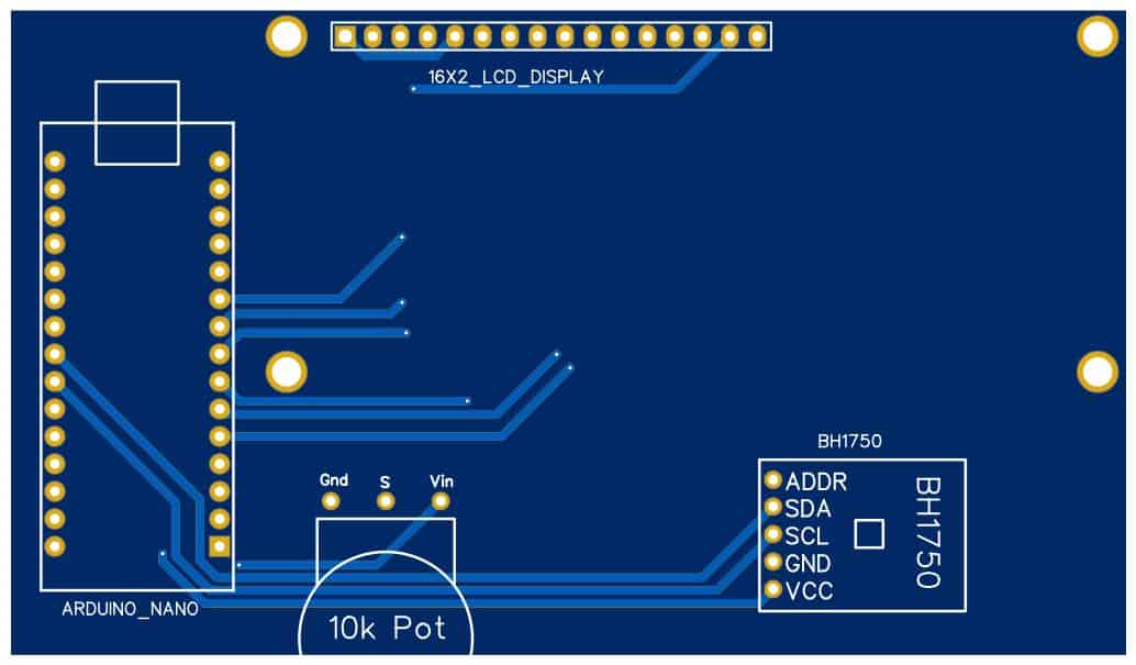
Now let us interface the BH1750 Ambient Light Sensor with Arduino & make a Simple Light Meter. The connection diagram is given below.

The BH1750 works on the I2C protocol. So, connect its SCL & SDA pins to A5 & A4 of Arduino respectively. The Sensor VCC pin can be connected to a 3.3V or 5V Pin. Connect the GND pin to GND.
The 16X2 LCD pins 1,5,16 is connected to GND. The pin 2 & 15 is connected to 5V of Arduino. Similarly, the pin 4, 6, 11, 12, 13, 14 is connected to Arduino 12, 11, 5, 4, 3, 2 pins.
Project PCB Gerber File & PCB Ordering Online
If you don’t want to assemble the circuit on breadboard and you want PCB for the project, then here is the PCB for you. The PCB Board for the Light Meter is designed using EasyEDA online Circuit Schematics & PCB designing tool. The front side and back side of the PCB is given below.

The Gerber File for the PCB is given below. You can simply download the Gerber File and order the PCB from ALLPCB at 1$ only.
You can use this Gerber file to order high quality PCB for this project. To do that visit the ALLPCB official website by clicking here: https://www.allpcb.com/.

You can now upload the Gerber File by choosing the Quote Now option. From these options, you can choose the Material Type, Dimensions, Quantity, Thickness, Solder Mask Color and other required parameters.

After filling all details, select your country and shipping method. Finally you can place the order.
Source Code/Program
Before uploading the code to the Arduino Board, we need BH1750 Library added to the Library folder. Download the BH1750 Arduino library from the following link below.
|
1 2 3 4 5 6 7 8 9 10 11 12 13 14 15 16 17 18 19 20 21 22 23 24 25 26 27 28 29 30 |
#include <Wire.h> // adds I2C library #include <BH1750.h> // adds BH1750 library file #include<LiquidCrystal.h> // include LCD library function LiquidCrystal lcd (12, 11, 5, 4, 3, 2); //RS, E, D4, D5, D6, D7 BH1750 lightMeter; // Initialization of library functions and codes void setup() { Serial.begin(9600); // set serial buad rate of 9600 Wire.begin(); // Enable I2C pins of Arduino lcd.begin(16, 2); // Defines LCD size to 16x2 lcd.print("Illuminance"); //Print "Intensity in LUX" message on first line LCD lightMeter.begin(); delay(2000); } void loop() { float lux = lightMeter.readLightLevel(); lcd.setCursor(0, 1); lcd.print(lux); lcd.print(" lx"); delay(1000); } |
Testing BH1750 Sensor
Once the code is uploaded, the LCD will start displaying the light intensity in Lux. You can bring the Torchlight or Mobile phone light in front of the sensor to read the Illuminance value. Or you can take the device outside the room to measure the sunshine value in lux.


")


1 Comment
hello, I ask is you can help me to rebuild this mantage but with 4 BH1750 sensors, because I do not know much in the field of Arduino. Thank you