Close Menu
  • Articles
    • Learn Electronics
    • Product Review
    • Tech Articles
  • Electronics Circuits
    • 555 Timer Projects
    • Op-Amp Circuits
    • Power Electronics
  • Microcontrollers
    • Arduino Projects
    • STM32 Projects
    • AMB82-Mini IoT AI Camera
    • BLE Projects
  • IoT Projects
    • ESP8266 Projects
    • ESP32 Projects
    • ESP32 MicroPython
    • ESP32-CAM Projects
    • LoRa/LoRaWAN Projects
  • Raspberry Pi
    • Raspberry Pi Projects
    • Raspberry Pi Pico Projects
    • Raspberry Pi Pico W Projects
  • Electronics Calculator
Facebook X (Twitter) Instagram
  • About Us
  • Disclaimer
  • Privacy Policy
  • Contact Us
  • Advertise With Us
Facebook X (Twitter) Instagram Pinterest YouTube LinkedIn
How To Electronics
  • Articles
    • Learn Electronics
    • Product Review
    • Tech Articles
  • Electronics Circuits
    • 555 Timer Projects
    • Op-Amp Circuits
    • Power Electronics
  • Microcontrollers
    • Arduino Projects
    • STM32 Projects
    • AMB82-Mini IoT AI Camera
    • BLE Projects
  • IoT Projects
    • ESP8266 Projects
    • ESP32 Projects
    • ESP32 MicroPython
    • ESP32-CAM Projects
    • LoRa/LoRaWAN Projects
  • Raspberry Pi
    • Raspberry Pi Projects
    • Raspberry Pi Pico Projects
    • Raspberry Pi Pico W Projects
  • Electronics Calculator
How To Electronics
Home » LED Control using Push Button with Raspberry Pi Pico
Raspberry Pi Raspberry Pi Pico Projects

LED Control using Push Button with Raspberry Pi Pico

Mamtaz AlamBy Mamtaz AlamUpdated:October 2, 20223 Comments2 Mins Read
Share Facebook Twitter LinkedIn Telegram Reddit WhatsApp
Raspberry Pi Pico LED Push Button
Share
Facebook Twitter LinkedIn Pinterest Email Reddit Telegram WhatsApp

Overview

In this guide we will learn how to control any LED by pressing a push button or a switch by interfacing them with Raspberry Pi Pico.

The Raspberry Pi Pico detects the level change of the button to determine whether the button was pressed. Press the button to turn on the LED light for the first time, and press the button to turn off the LED light again, so as to realize the function of turning on and off the LED light.


Components Required

In this guide, I used Elecrow Raspberry Pi Pico Starter Kit to test different Modules. You can buy the kit and perform some other operations as well. From this kit, you can use the following components.

1. Raspberry Pi Pico Board -1
2. Push Button Switch – 1
3. LED – 1
4. Breadboard -1
5. Jumper Wires – 4


Push Button Switch

Push Button Switch

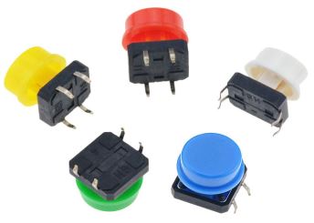
A Push button, also known as a tact switch, is a kind of electronic component. Its internal structure is connected and disconnected by the force change of metal shrapnel. When in use, press the switch, The switch is closed and the circuit is turned on. When released, the switch bounces and the circuit is disconnected.


Circuit Diagram & Hardware Setup

Now let us see how we can Control LED using Push Button Switch by interfacing it with Raspberry Pi Pico Board. Here is the simple connection diagram.

LED Control using Push Button with Raspberry Pi Pico

Connect the Push Button Pin to GP0 & its cross pin to GND. Similarly, connect the LED positive Pin to Raspberry Pi Pico GP1 Pin & negative Pin to GND Pin.

Push Button Switch LED Control


MicroPython Code/Program

Copy the following Code to the Thonny Editor.

1
2
3
4
5
6
7
8
9
10
11
12
13
14
15
16
17
18
19
from machine import Pin
from utime import sleep_ms
button = Pin(0, Pin.IN, Pin.PULL_UP)   #Internal pull-up
led = Pin(1, Pin.OUT)
State=0                                #0 means that the light is currently off
if __name__ == '__main__':
    while True:
        print(button.value())
        if button.value() == 0:       #key press
            if State==0:
                led.value(1)
                sleep_ms=100
                while button.value() == 0:
                   State=1        
            else:
                led.value(0)
                sleep_ms=100
                while button.value()== 0:
                    State=0

Run the script and you can start checking the LED State by pressing the button.

When a button is pressed the LED will turn ON.

If the same button is pressed for the second time, the LED state will toggle and LED will turn off.

Share. Facebook Twitter Pinterest LinkedIn Tumblr Email Reddit Telegram WhatsApp
Previous ArticleControlling RGB LED using Raspberry Pi Pico
Next Article Voice Activated Light with Sound Sensor & Raspberry Pi Pico

Related Posts

ADXL375 Accelerometer with Raspberry Pi Pico & MicroPython

ADXL375 Accelerometer with Raspberry Pi Pico & MicroPython

Updated:July 24, 2025
Interface BMI160 with Raspberry Pi Pico & MicroPython

Interface BMI160 with Raspberry Pi Pico & MicroPython

Updated:February 2, 20253K
Shift Register 74HC595 with Raspberry Pi Pico & MicroPython

Shift Register 74HC595 with Raspberry Pi Pico & MicroPython

Updated:February 2, 202513K
Interfacing XBee Module with Raspberry Pi Pico & MicroPython

Interfacing XBee Module with Raspberry Pi Pico & MicroPython

Updated:February 2, 20253K
Modbus RTU with Raspberry Pi Pico & Micropython

Modbus RTU with Raspberry Pi Pico & MicroPython

Updated:February 2, 20258K
Fever Detector with MLX90640 & OpenCV Raspberry Pi

Thermal Fever Detector with MLX90640 & OpenCV Raspberry Pi

Updated:February 2, 20256K
View 3 Comments

3 Comments

  1. Mike on February 6, 2023 10:25 PM

    nice example, this worked like a charm. However im uncertain what difference Pin.PULL_UP makes? initially i didnt use it and than began to test with and without Pin.PULL_UP.

    Reply
  2. Gordon on February 24, 2023 12:27 PM

    It’s just to stop the pin from floating voltages when there is no contact. If you set the pin as PULL_UP then it defaults to pin.value as 1, and you would have to ground it to change it to a 0. If you set the pin as PULL_DOWN then it’s opposite, value 0 till you feed it a positive voltage. Prevents phantom states 😀 I don’t even know if that’s a term but I think it sounds cool so I’m coining it!

    Reply
  3. JOne on May 10, 2025 5:07 PM

    THIS IS TOTALLY WRONG !!
    – YOU SHOULD NEVER POWER AN LED DIRECTLY FROM A MCU PIN!!!
    – ALL LEDS MUST HAVE A RESISTANCE IN SERIES TO LIMIT THE CURRENT!!!!
    – THOSE WHO DON’T KNOW WHAT THEY’RE DOING SHOULD NOT COME TO THE INTERNET TO GIVE BAD EXAMPLES!!!!

    Reply

CommentsCancel reply

Latest Posts
IoT Based PM & Air Quality Monitoring System using ESP32

IoT Based PM & Air Quality Monitoring System using ESP32

May 31, 2026
DIY ESP32 MLX90640 IR Thermal Camera with Live Web Display

DIY ESP32 MLX90640 IR Thermal Camera with Live Web Display

May 10, 2026
IoT Activity Tracker with ESP32 & Accelerometer Gyroscope

IoT Activity Tracker with ESP32 & Accelerometer/Gyroscope

May 2, 2026
A Guide to Sourcing Obsolete ICs for Vintage Projects

Beyond AliExpress: A Guide to Sourcing Obsolete ICs for Vintage Projects

April 21, 2026

ESP32 IoT Vehicle Motion Analyzer with MPU6050 & LIS3MDL

April 27, 2026
Building a Smart Sensor Node with a BLE Microcontroller

Building a Smart Sensor Node with a BLE Microcontroller

February 26, 2026
High-Accuracy Pitch, Roll, Yaw with ESP32 & BNO08x IMU

High-Accuracy Pitch, Roll, Yaw with ESP32 & BNO08x IMU

April 27, 2026
DIY Colorimeter using AS7265x Spectroscopy Sensor & ESP32

DIY Colorimeter using AS7265x Spectroscopy Sensor & ESP32

February 1, 2026
Top Posts & Pages
  • 12V DC to 220V AC Inverter Circuit & PCB
    12V DC to 220V AC Inverter Circuit & PCB
  • IoT AC Energy Meter with PZEM-004T & ESP32 WebServer
    IoT AC Energy Meter with PZEM-004T & ESP32 WebServer
  • IoT Based Drinking Water Quality Monitoring with ESP32
    IoT Based Drinking Water Quality Monitoring with ESP32
  • LD2410 Sensor with ESP32 - Human Presence Detection
    LD2410 Sensor with ESP32 - Human Presence Detection
  • ESP32 CAN Bus Tutorial | Interfacing MCP2515 CAN Module with ESP32
    ESP32 CAN Bus Tutorial | Interfacing MCP2515 CAN Module with ESP32
  • DIY IoT Water pH Meter using pH Sensor & ESP32
    DIY IoT Water pH Meter using pH Sensor & ESP32
  • Buck Converter: Basics, Working, Design & Application
    Buck Converter: Basics, Working, Design & Application
  • How to use Modbus RTU with ESP32 to read Sensor Data
    How to use Modbus RTU with ESP32 to read Sensor Data
Categories
  • Arduino Projects (197)
  • Articles (60)
    • Learn Electronics (19)
    • Product Review (15)
    • Tech Articles (28)
  • Electronics Circuits (46)
    • 555 Timer Projects (21)
    • Op-Amp Circuits (7)
    • Power Electronics (13)
  • IoT Projects (204)
    • ESP32 MicroPython (7)
    • ESP32 Projects (81)
    • ESP32-CAM Projects (15)
    • ESP8266 Projects (76)
    • LoRa/LoRaWAN Projects (22)
  • Microcontrollers (38)
    • AMB82-Mini IoT AI Camera (4)
    • BLE Projects (18)
    • STM32 Projects (19)
  • Raspberry Pi (93)
    • Raspberry Pi Pico Projects (57)
    • Raspberry Pi Pico W Projects (12)
    • Raspberry Pi Projects (24)
Follow Us
  • Facebook
  • Twitter
  • Pinterest
  • Instagram
  • YouTube
About Us

“‘How to Electronics’ is a vibrant community for electronics enthusiasts and professionals. We deliver latest insights in areas such as Embedded Systems, Power Electronics, AI, IoT, and Robotics. Our goal is to stimulate innovation and provide practical solutions for students, organizations, and industries. Join us to transform learning into a joyful journey of discovery and innovation.

Copyright © How To Electronics. All rights reserved.
  • About Us
  • Disclaimer
  • Privacy Policy
  • Contact Us
  • Advertise With Us

Type above and press Enter to search. Press Esc to cancel.

Ad Blocker Enabled!
Ad Blocker Enabled!
Looks like you're using an ad blocker. Please allow ads on our site. We rely on advertising to help fund our site.