

Overview: IoT Based Smart Kitchen
In this project, we will build an IoT Based Smart Kitchen with Automation & Monitoring System using NodeMCU ESP8266. The kitchen is one of the important places in a house. The safety factor is the main aspect that must be taken into account during the activity in the kitchen. The existence of gas leakage, uncontrolled fire, excessive temperatures & a moist environment must be quickly identified and addressed. Apart from this, it is necessary to monitor & control Kitchen Appliances like lights, fridge, oven, etc remotely.

The main motto of this project is to make a prototype of an IoT Based Smart Kitchen using the Internet of Things. The system uses multiple sensors, relays & NodeMCU ESP8266 Board. We can monitor all the sensor data on Blynk Applications. We can also send the command from Blynk App to control Kitchen Appliances.
Basically, the IoT Smart Kitchen does the following tasks:
- Monitor the Kitchen Temperature & Humidity using DHT11 Sensor on Blynk App
- Monitor the Air Quality Index (Gas) using MQ-135 Gas Sensor on Blynk App
- Displays the Kitchen Temperature, Humidity & Gas Level on 0.96″ OLED Display
- The exhaust fan turns ON & the Alarm activates, once Gas level exceeds
- Detects the presence or absence of a person in the Kitchen using a PIR sensor
- Sends Alarm Staus, Exhaust Fan Status & Person in Room Status to Blynk App
- User can turn ON/OFF Fridge, Oven, Room Light Remotely from Blynk App
Bill of Materials
We need following electronics components to make IoT Based Smart Kitchen project. All the components are easily available in Amazon & you can purchase them easily from the following link.
| S.N. | Components Name | Quantity | Purchase Links |
|---|---|---|---|
| 1 | ESP8266 WiFi Module | 1 | Amazon | AliExpress |
| 2 | DHT11 Sensor | 1 | Amazon | AliExpress |
| 3 | MQ-135 Air Quality Sensor | 1 | Amazon | AliExpress |
| 4 | HC-SR501 PIR Sensor | 1 | Amazon | AliExpress |
| 5 | 0.96" I2C OLED Display | 1 | Amazon | AliExpress |
| 6 | Buzzer 5V | 1 | Amazon | AliExpress |
| 7 | 4 Channel Relay Module | 1 | Amazon | AliExpress |
| 8 | Jumper Wires | 20 | Amazon | AliExpress |
| 9 | Breadboard | 1 | Amazon | AliExpress |
| 10 | USB Cable | 1 | Amazon | AliExpress |
System Design & Circuit Diagram
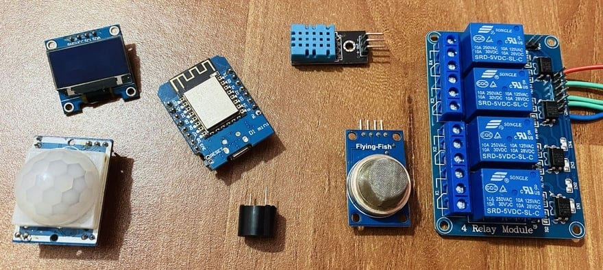
We will utilize the sensors like DHT11 Humidity Temperature Sensor, MQ-135 Gas Sensor, Passive Infrared Sensor to monitor the Indoor Air Quality Parameters. Similarly, a simple 5V buzzer can work as an alarming system. An automatic exhaust Fan is connected to a relay which activates automatically when the gas level exceeds the threshold value.
Since we are using 4 channel relay, the remaining 3 relays can be connected to kitchen appliances like Mixer, Refrigerator, Oven, Water Heater, Induction, etc. A simple 0.96″ I2C OLED can Display room temperature, humidity, and gas value live. The heart and brain of this project are Wemos D1 Mini Board or NodeMCU ESP8266 Board. You can use any of the ESP8266-12E based boards. The ESP8266 chip connects to the WiFi Network and establishes a connection with Blynk Application.
Here is a simple schematic designed using Fritzing software.

Use the following schematic as a reference and assemble the circuit on a breadboard. Connect the OLED Display SDA & SCL pins to Wemos D2 & D1 Pin. Similarly, connect the DHT11, MQ-135 & PIR Sensor output pin to the D4, A0 & D3 pin of Wemos. For the alarm system, you can connect the 5V active Buzzer to the D0 Pin of Wemos. For controlling the Home Appliances, we can use 4 channel Relay Module. So using the jumper wires, connect the 4 channel relay input pin to the D5, D6, D7 & D8 of Wemos.

Project PCB Gerber File & PCB Ordering Online
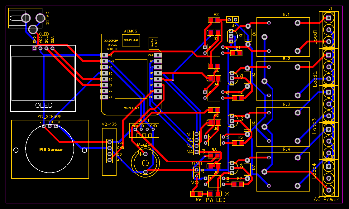
If you don’t want to assemble the circuit on a breadboard and you want PCB for the project, then here is the PCB for you. I first designed the Schematic using the using the EasyEDA online Circuit Schematics & PCB designing tool.

Then I converted the schematic to a PCB. The PCB Board for IoT Based Smart Kitchen looks something like below.
The Gerber File for the PCB is given below. You can simply download the Gerber File and order the PCB from ALLPCB at 1$ only.

You can now upload the Gerber File by choosing the Quote Now option. From these options, you can choose the Material Type, Dimensions, Quantity, Thickness, Solder Mask Color and other required parameters.

After filling all details, select your country and shipping method. Finally you can place the order.
You can assemble the components on the PCB Board.

Setting Up Blynk Application
Now we need to setup the Blynk Application so that we can receive the data from ESP8266. The Blynk Application used here is for IoT Based Smart Kitchen using NodeMCU ESP8266.
Blynk is an application that runs over Android and IOS devices to monitor any IoT based application using Smartphones. It allows you to create your Graphical user interface for IoT application. Here we will display the room temperature, himidity & Air Quality data & control kitchen appliances.
- So download and install the Blynk Application from Google Play Store. IOS users can download from the App Store. Once the installation is completed, open the app & sign-up using your Email id and Password.
- From the dashboard create a new project and select NodeMCU Board & Wifi Connection.

-
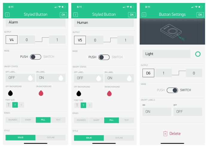
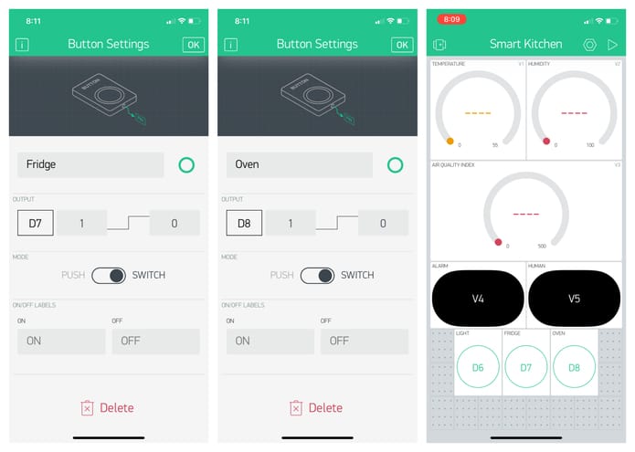
Then drag & drop or add 3 buttons, 2 style buttons, and 3 gauge from the widget list.
-
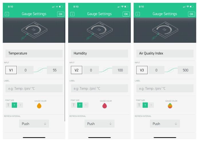
Assign the 3 variables and name them like temperature, humidity & Air Quality Index Value as per code.
-
Similarly, assign the 3 variables for the button and 2 variables for the styled button.

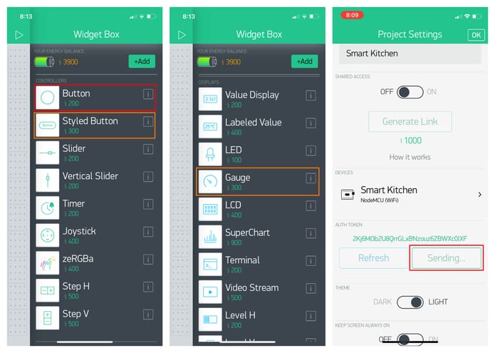
- You will get the authentication code in the mail. Copy this authentication code. This will be used in your code.

Source Code/Program: IoT Smart Kitchen
The source code for IoT Based Smart Kitchen Automation & Monitoring with NodeMCU ESP8266 & Blynk is given below. But before going for the code part, we need to add the following libraries to the Arduino IDE.
1. DHT11 Library: Download
2. MQ-135 Library: Download
3. Adafruit GFX Library: Download
4. Adafruit SSD1306 Library: Download
5. Blynk ESP8266 Library: Download
After adding all these libraries, the code will compile easily. But for establishing Wifi connection and connecting Blynk with Wemos ESP8266 Board, change the Wifi SSID, Password & Blynk Authentication Token.
|
1 2 3 |
char auth[] = "**************************"; //Get Auth Token in the Blynk App. char ssid[] = "**************************"; // Your WiFi credentials. char pass[] = "**************************"; |
Here is a complete code for the project. Paste this code on the Arduino IDE. Then select the Wemos D1 board from the Board manager & also select the port and upload the code.
|
1 2 3 4 5 6 7 8 9 10 11 12 13 14 15 16 17 18 19 20 21 22 23 24 25 26 27 28 29 30 31 32 33 34 35 36 37 38 39 40 41 42 43 44 45 46 47 48 49 50 51 52 53 54 55 56 57 58 59 60 61 62 63 64 65 66 67 68 69 70 71 72 73 74 75 76 77 78 79 80 81 82 83 84 85 86 87 88 89 90 91 92 93 94 95 96 97 98 99 100 101 102 103 104 105 106 107 108 109 110 111 112 113 114 115 116 117 118 119 120 121 122 123 124 125 126 127 128 129 130 131 132 133 134 135 136 137 138 139 140 141 142 143 144 145 146 147 148 149 150 151 152 153 154 155 156 157 158 159 160 161 162 163 164 165 166 167 |
#define BLYNK_PRINT Serial #include <ESP8266WiFi.h> #include <BlynkSimpleEsp8266.h> #include <SPI.h> #include <Wire.h> #include "MQ135.h" #include <Adafruit_Sensor.h> #include <DHT.h> #include <Adafruit_GFX.h> #include <Adafruit_SSD1306.h> char auth[] = "**************************"; // You should get Auth Token in the Blynk App. char ssid[] = "**************************"; // Your WiFi credentials. char pass[] = "**************************"; #define SCREEN_WIDTH 128 // OLED display width, in pixels #define SCREEN_HEIGHT 64 // OLED display height, in pixels #define OLED_RESET -1 // Reset pin # (or -1 if sharing Arduino reset pin) #define DHTTYPE DHT11 // DHT 11 #define DHTPIN D4 #define relay_fan D5 #define relay_light D6 #define relay_fridge D7 #define relay_oven D8 #define buzzer_alarm D0 #define pir_human D3 int alarm_status; int pir_status = 0; DHT dht(DHTPIN, DHTTYPE); Adafruit_SSD1306 display(SCREEN_WIDTH, SCREEN_HEIGHT, &Wire, OLED_RESET); void setup() { Serial.begin(115200); dht.begin(); display.begin(SSD1306_SWITCHCAPVCC, 0x3C); //initialize with the I2C addr 0x3C (128x64) Blynk.begin(auth, ssid, pass); pinMode(pir_human, INPUT); pinMode(buzzer_alarm, OUTPUT); pinMode(relay_fan, OUTPUT); pinMode(relay_light, OUTPUT); pinMode(relay_fridge, OUTPUT); pinMode(relay_oven, OUTPUT); digitalWrite(buzzer_alarm, LOW); digitalWrite(relay_fan, HIGH); digitalWrite(relay_light, HIGH); digitalWrite(relay_fridge, HIGH); digitalWrite(relay_oven, HIGH); delay(100); } void loop() { Blynk.run(); MQ135 gasSensor = MQ135(A0); float air_quality = gasSensor.getPPM(); float t = dht.readTemperature(); float h = dht.readHumidity(); pir_status = digitalRead(pir_human); alarm_status = digitalRead(buzzer_alarm); if (pir_status == 1) { Serial.println("Person Detected"); } else if (pir_status == 0) { Serial.println("No One in Room"); } if (air_quality > 150) { digitalWrite(buzzer_alarm, HIGH); digitalWrite(relay_fan, LOW); Serial.println("Buzzer Status: ON"); Serial.println("Exhaust Fan: ON"); } else { digitalWrite(buzzer_alarm, LOW); digitalWrite(relay_fan, HIGH); Serial.println("Buzzer Status: OFF"); Serial.println("Exhaust Fan: OFF"); } Serial.print("Air Quality: "); Serial.print(air_quality); Serial.println(" PPM"); Serial.print("Temperature: "); Serial.print(t); Serial.println(" *C"); Serial.print("Humidity: "); Serial.print(h); Serial.println(" %"); Serial.println(); Serial.println("****************************"); Serial.println(); Blynk.virtualWrite(V1, t); // For Temperature Blynk.virtualWrite(V2, h); // For Humidity Blynk.virtualWrite(V3, air_quality); // For Gas Blynk.virtualWrite(V4, alarm_status); // For Alarm & Exhaust Fan Blynk.virtualWrite(V5, pir_status); // For Human Detection display.clearDisplay(); display.setCursor(0, 0); //oled display display.setTextSize(1); display.setTextColor(WHITE); display.println("Air Quality Index"); display.setCursor(0, 20); //oled display display.setTextSize(2); display.setTextColor(WHITE); display.print(air_quality); display.setTextSize(1); display.setTextColor(WHITE); display.println(" PPM"); display.display(); delay(1500); display.clearDisplay(); // display temperature display.setTextSize(1); display.setCursor(0, 0); display.print("Temperature: "); display.setTextSize(2); display.setCursor(0, 10); display.print(t); display.print(" "); display.setTextSize(1); display.cp437(true); display.write(167); display.setTextSize(2); display.print("C"); // display humidity display.setTextSize(1); display.setCursor(0, 35); display.print("Humidity: "); display.setTextSize(2); display.setCursor(0, 45); display.print(h); display.print(" %"); display.display(); delay(1500); } |
Testing of IoT Smart Kitchen Project
After uploading the code, the Wemos D1 Board tries connecting to the WiFi network using the given SSID & Password. Meanwhile, you can open the Serial Monitor as well. The Serial Monitor will display the Humidity, Temperature, Air Quality Index, Alarm Status, Human Presence, etc.

On the other hand the OLED Display will display the Temperature, Humidity & Gas Level of the Kitchen.

Once it connects to the WiFi Network it will start sending the data to the Blynk Application.
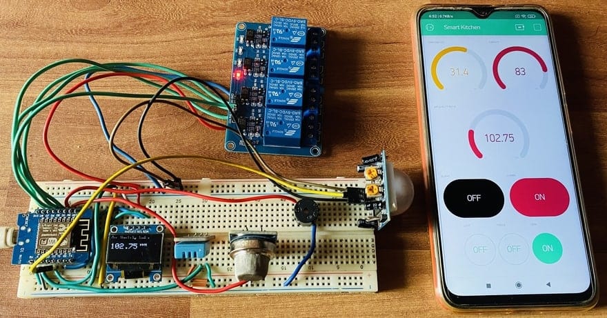
The Blynk Application will receive the Temperature, Humidity & Air Quality Index Data and display them on the Gague. It will also show whether the alarm is ON or OFF as well as the presence of humans inside the room or not.

The Relay one that connects to the exhaust fan automatically activates when the Gas level reaches threshold Value. The threshold value is set to 150 PPM. You can set it to any desired value. You can send the command from the Blynk Application to turn on the Kitchen Appliances like Fridge, Oven & lights.
This is how you can design your own IoT Based Smart Kitchen using NodeMCU ESP8266 with Automation & Monitoring System on Blynk Application.
Video Tutorial & Guide

 & Live Dashboard")


2 Comments
display.cp437(true); err
Can you show the finished project with the PCB board and how you hooked it all up?