

Introduction
In this project, we will introduce you to the Automatic Smart Toll Tax Collection System designed using RFID Module and Arduino. Nowadays there is a huge rush in toll plazas for paying the toll tax. Therefore, in order to reduce traffic and save time, an automatic toll collector can be used. The aim of the project is to automatically identify the RFID tag in a vehicle and to display the particular amount the user has to pay in order to pass the toll. If the user pays the amount, he can pass the gate else he will be blocked.
This project is a demo of a Smart Toll Tax Collection System. Consider there are n numbers of vehicles at Toll Plaza. When these vehicles cross the IR Sensor, the gate will be closed. At the same time, the LCD will display to put the Card to the reader for scanning. Then you can put your card on RFID and pay your bill. When the bill is successfully paid, then you can go towards the 2nd Gate. When a vehicle crosses the 2nd IR Sensor, the gate will be opened and you can go. In case the card doesn’t have a balance, you can recharge the card using this RFID and Keypad by entering the amount.
Thus this RFID Based Toll Tax Collection System can be used for Industrial applications or College Final Year projects. You can check some recent projects based on RFID & Arduino systems:
Bill of Materials
You need to buy the following components for this project.
| S.N. | Components | Quantity | |
|---|---|---|---|
| 1 | Arduino UNO Board | 1 | Amazon | AliExpress |
| 2 | RC522 RFID Reader | 1 | Amazon | AliExpress |
| 3 | 13.56 MHz RFID Card | 5 | Amazon | AliExpress |
| 5 | I2C LCD Display | 1 | Amazon | AliExpress |
| 6 | 4x4 Keypad Module | 1 | Amazon | AliExpress |
| 7 | IR Sensor Module E18-D80NK | 2 | Amazon | AliExpress |
| 8 | Servo Motor MG995 | 1 | Amazon | AliExpress |
| 9 | Resistor 1K | 4 | Amazon | AliExpress |
| 10 | Resistor 4.7K | 3 | Amazon | AliExpress |
| 11 | Zero PCB | 1 | Amazon | AliExpress |
| 12 | 9V DC Power Supply | 1 | Amazon | AliExpress |
System Overview of Automated Toll Collection System
The RFID reader checks for valid, invalid, or low balances. If invalid and low balance the LCD Screen will show insufficient balance. The RFID Card can be loaded to balance using the Keypad System. When the Card is recharged, the user becomes eligible for paying and going through the toll gate.
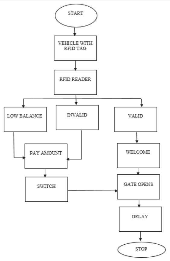
The toll gate is fitted to the Servo Motor where the spindle of the motor rotates in a fixed angle step. When the user swipes the card the reader sends the signal to the controller and the controller checks for a valid user. If the card is valid then the controller sends a signal to the Servo motor to rotate in an anticlockwise direction so the gate opens. Some delay function is added so that the gate remains open until the vehicle moves after some time delay the controller passes the signal to rotate the Servo motor in a clockwise direction to close the gate.
Circuit Diagram & Connection
The circuit for RFID Based Toll Tax Collection System is given below. The circuit is based on the above flowchart with the use of necessary electronic components.

The RFID RC522 is an SPI Module. Therefore Connect the RFID SPI Pin to Arduino as follows.
| RC522 Pins | Arduino Pins |
|---|---|
| SDA | 10 |
| SCK | 13 |
| MOSI | 11 |
| MISO | 12 |
| GND | GND |
| RST | 8 |
| 3.3V | 3.3V |
The 16×2 LCD Display is an I2C Module. Therefore Connect the I2C LCD Pin to Arduino as follows.
| LCD Pins | Arduino |
|---|---|
| VCC | 5V |
| GND | GND |
| SDA | A4 |
| SCL | A5 |
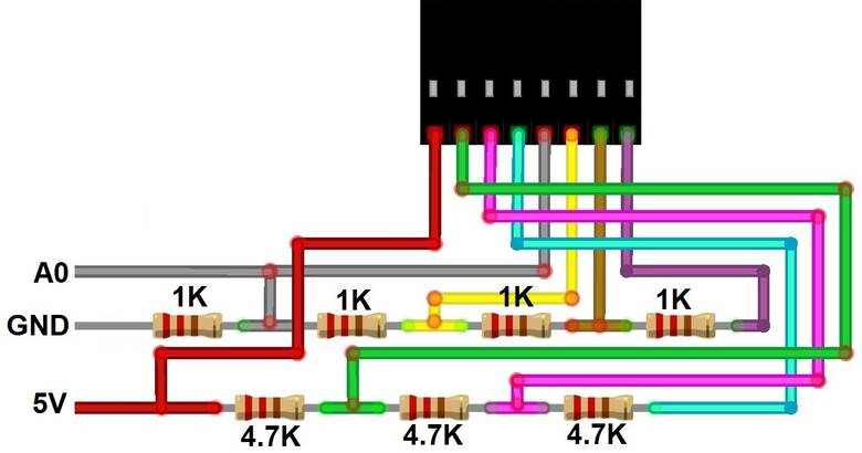
The 4×4 Keypad Matrix has a total of 8 Pins. Hence it requires 8 digital Pin of Arduino for connection. In order to minimize the pin from 8 to 1, we will utilize a single analog pin. Using an array of resistors a voltage divider network can be formed so that whenever a button is pressed a different analog voltage is taken as an input.
We have a Servo Motor MG995 which is controlled using PWM Digital Pin 9 of Arduino.
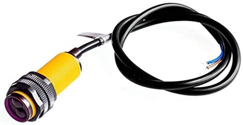
Similarly we used a Pair of Infrared Proximity Switch – E18-D80NK to detect motion of a moving car travelling across the gate.
Connect the VCC & GND of both the IR Proximity Sensor to the 5V & GND of Arduino. Similarly, connect their output pin A2 & A3 of the Arduino Board.

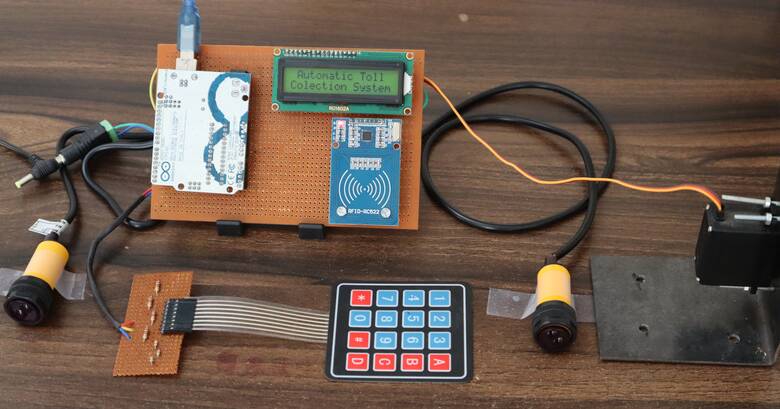
The Mechanical Arrangement if the project looks something like shown in the image above. Thus the hardware setup for the Automated Toll Collection System using RFID & Arduino is ready for testing.
Project PCB Gerber File & PCB Ordering Online
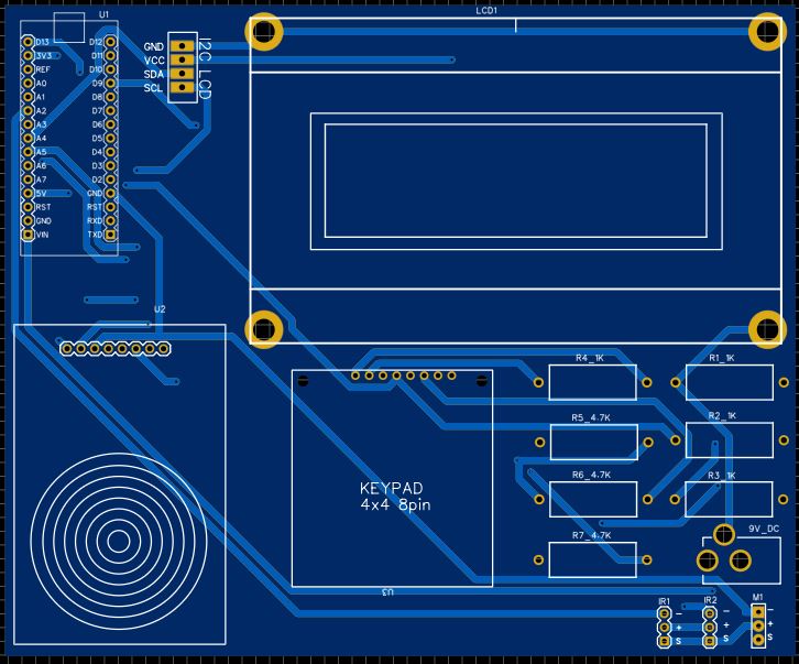
If you don’t want to assemble the circuit on a breadboard and you want PCB for the project, then here is the PCB for you. I used EasyEDA to design the Schematic & PCB. The Schematic & PCB Board for RFID Toll Collection System using Arduino looks something like the below.


The Gerber File for the PCB is given below. You can simply download the Gerber File and order the PCB from ALLPCB at 1$ only.
You can use this Gerber file to order high quality PCB for this project. To do that visit the ALLPCB official website by clicking here: https://www.allpcb.com/.

You can now upload the Gerber File by choosing the Quote Now option. From these options, you can choose the Material Type, Dimensions, Quantity, Thickness, Solder Mask Color and other required parameters.

After filling all details, select your country and shipping method. Finally you can place the order.
You can assemble the components on the PCB Board.
Source Code/Program
The complete code for the Automated Toll Collection System using RFID & Arduino is given below. The code requires some libraries. Download the zip library from the following link below and add to to the Arduino IDE using the Library manager.
1. RC522 Library: https://github.com/miguelbalboa/rfid
2. One Wire Keypad Library: https://github.com/ProgettoCompany/One_Pin_Keypad_Arduino_Library
3. Liquid Crystal I2C Library: https://github.com/fdebrabander/Arduino-LiquidCrystal-I2C-library
In the following code, make changes to the balance, that you want to assign for the RFID Cards.
|
1 2 |
int card1Balance = 4000; int card2Balance = 200; |
Make changes to the RFID Tag number as every RFID Card has its own tag number. Change all the lines with the RFID tag number that looks like this.
|
1 |
if (content.substring(1) == "63 5B 9F 17") |
Copy the following code and upload it to the Arduino Board.
|
1 2 3 4 5 6 7 8 9 10 11 12 13 14 15 16 17 18 19 20 21 22 23 24 25 26 27 28 29 30 31 32 33 34 35 36 37 38 39 40 41 42 43 44 45 46 47 48 49 50 51 52 53 54 55 56 57 58 59 60 61 62 63 64 65 66 67 68 69 70 71 72 73 74 75 76 77 78 79 80 81 82 83 84 85 86 87 88 89 90 91 92 93 94 95 96 97 98 99 100 101 102 103 104 105 106 107 108 109 110 111 112 113 114 115 116 117 118 119 120 121 122 123 124 125 126 127 128 129 130 131 132 133 134 135 136 137 138 139 140 141 142 143 144 145 146 147 148 149 150 151 152 153 154 155 156 157 158 159 160 161 162 163 164 165 166 167 168 169 170 171 172 173 174 175 176 177 178 179 180 181 182 183 184 185 186 187 188 189 190 191 192 193 194 195 196 197 198 199 200 201 202 203 204 205 206 207 208 209 210 211 212 213 214 215 216 217 218 219 220 221 222 223 224 225 226 227 228 229 230 231 232 233 234 235 236 237 238 239 240 241 242 243 244 245 246 247 248 249 250 251 252 253 254 255 256 257 258 259 260 261 262 263 264 265 266 267 268 269 270 271 272 273 274 275 276 277 278 279 280 281 282 283 284 285 286 287 288 289 290 291 292 293 294 295 296 297 298 299 300 301 302 303 304 305 306 307 308 309 310 311 312 313 314 315 316 317 318 319 320 321 322 323 324 325 326 327 328 329 330 331 332 333 334 335 336 337 338 339 340 341 342 343 344 345 346 347 348 349 350 351 352 353 354 355 356 357 358 359 360 361 362 |
#include <SPI.h> #include <MFRC522.h> #include <OnewireKeypad.h> #include <Servo.h> #include <LiquidCrystal_I2C.h> LiquidCrystal_I2C lcd(0x27, 16, 2); Servo servo; int servoPos = 0; #define sensorPin1 A2 #define sensorPin2 A3 #define buzzerPin 3 int senVal1 = 0; int senVal2 = 0; #define RST_PIN 8 #define SS_PIN 10 int card1Balance = 4000; int card2Balance = 200; #define num 7 char Data[num]; byte data_count = 0; String num1, num2, card, card2; int a, b; char Key; bool recharge = true; MFRC522 mfrc522(SS_PIN, RST_PIN); int state = 0; char KEYS[] = { '1', '2', '3', 'A', '4', '5', '6', 'B', '7', '8', '9', 'C', '*', '0', '#', 'D' }; OnewireKeypad <Print, 16 > KP2(Serial, KEYS, 4, 4, A0, 4700, 1000, ExtremePrec ); void setup () { lcd.begin(); lcd.backlight(); Serial.begin(9600); servo.attach(9); servo.write(30); pinMode(sensorPin1, INPUT); pinMode(sensorPin2, INPUT); pinMode(buzzerPin, OUTPUT); KP2.SetKeypadVoltage(5.0); SPI.begin(); mfrc522.PCD_Init(); lcd.setCursor(0, 0); lcd.print(" Automatic Toll"); lcd.setCursor(0, 1); lcd.print("Colection System"); delay(3000); lcd.clear(); } void loop() { if (recharge == 0) { reCharge(); } else { lcd.setCursor(0, 0); lcd.print(" Welcome"); sensorRead(); rfid(); KeyPad(); if (senVal1 == 0) { servoDown(); lcd.clear(); lcd.setCursor(0, 0); lcd.print("Vehicle Detected"); delay(1000); lcd.clear(); lcd.setCursor(0, 0); lcd.print("Put Your Card To"); lcd.setCursor(0, 1); lcd.print("The Reader......"); delay(2000); lcd.clear(); } else if (senVal2 == 0 && state == 1) { servoUp(); lcd.clear(); lcd.setCursor(0, 0); lcd.print("Have A Safe"); lcd.setCursor(0, 1); lcd.print("Journey"); delay(1000); lcd.clear(); state = 0; } } } void servoDown() { servo.attach(9); for (servoPos = 30; servoPos <= 120; servoPos += 1) { servo.write(servoPos); delay(5); } } void servoUp() { servo.attach(9); for (servoPos = 120; servoPos >= 30; servoPos -= 1) { servo.write(servoPos); delay(5); } } void sensorRead() { senVal1 = digitalRead(sensorPin1); senVal2 = digitalRead(sensorPin2); } void rfid() { if ( ! mfrc522.PICC_IsNewCardPresent()) { return; } if ( ! mfrc522.PICC_ReadCardSerial()) { return; } String content = ""; for (byte i = 0; i < mfrc522.uid.size; i++) { content.concat(String(mfrc522.uid.uidByte[i] < 0x10 ? " 0" : " ")); content.concat(String(mfrc522.uid.uidByte[i], HEX)); } content.toUpperCase(); if (content.substring(1) == "63 5B 9F 17") { if (card1Balance >= 500) { lcdPrint(); card1Balance = card1Balance - 500; lcd.setCursor(9, 1); lcd.print(card1Balance); delay(2000); lcd.clear(); state = 1; } else { card = content.substring(1); LcdPrint(); lcd.setCursor(9, 1); lcd.print(card1Balance); lcd.print(" Tk"); delay(2000); lcd.clear(); lcd.setCursor(0, 0); lcd.print("Please Recharge"); delay(1000); lcd.clear(); state = 0; } } else if (content.substring(1) == "9D B9 BE 09") { if (card2Balance >= 500) { lcdPrint(); card2Balance = card2Balance - 500; lcd.setCursor(9, 1); lcd.print(card2Balance); delay(2000); lcd.clear(); state = 1; } else { card = content.substring(1); LcdPrint(); lcd.setCursor(9, 1); lcd.print(card2Balance); lcd.print(" Tk"); delay(2000); lcd.clear(); lcd.setCursor(0, 0); lcd.print("Please Recharge"); lcd.clear(); delay(1000); state = 0; } } else { digitalWrite(buzzerPin, HIGH); lcd.setCursor(0, 0); lcd.print("Unknown Vehicle"); lcd.setCursor(0, 1); lcd.print("Access denied"); delay(1500); lcd.clear(); digitalWrite(buzzerPin, LOW); } } void KeyPad() { byte KState = KP2.Key_State(); if (KState == PRESSED) { Key = KP2.Getkey(); if (Key) { if (Key == 'A') { lcd.clear(); lcd.setCursor(0, 0); lcd.print("Recharging Mode."); lcd.setCursor(0, 1); lcd.print("................"); delay(1500); lcd.clear(); recharge = 0; } } } } void clearData() { while (data_count != 0) { Data[data_count--] = 0; } return; } void reCharge() { lcd.setCursor(0, 0); lcd.print ("Enter the amount"); byte KState = KP2.Key_State(); if (KState == PRESSED) { Key = KP2.Getkey(); if (Key) { if (Key == 'D') { if (card == "63 5B 9F 17") { num1 = Data; card1Balance = num1.toInt() + card1Balance; lcd.clear(); lcd.setCursor(0, 0); lcd.print("Your current"); lcd.setCursor(0, 1); lcd.print("balance: "); lcd.setCursor(9, 1); lcd.print (card1Balance); lcd.print(" Tk"); delay(3000); clearData(); lcd.clear(); recharge = 1; } else if (card == "9D B9 BE 09") { num2 = Data; card2Balance = num2.toInt() + card2Balance; lcd.clear(); lcd.setCursor(0, 0); lcd.print("Your current"); lcd.setCursor(0, 1); lcd.print("balance: "); lcd.setCursor(9, 1); lcd.print (card2Balance); lcd.print(" Tk"); delay(3000); clearData(); lcd.clear(); recharge = 1; } } else { Data[data_count] = Key; lcd.setCursor(data_count, 1); lcd.print(Data[data_count]); data_count++; } } } } void lcdPrint() { digitalWrite(buzzerPin, HIGH); delay(200); digitalWrite(buzzerPin, LOW); delay(100); lcd.clear(); lcd.setCursor(0, 0); lcd.print(" Successfully"); lcd.setCursor(0, 1); lcd.print(" paid your bill"); delay(1500); lcd.clear(); lcd.setCursor(0, 0); lcd.print("Your Remaining"); lcd.setCursor(0, 1); lcd.print("balance: "); } void LcdPrint() { digitalWrite(buzzerPin, HIGH); delay(200); digitalWrite(buzzerPin, LOW); delay(100); lcd.clear(); lcd.setCursor(0, 0); lcd.print(" Your balance"); lcd.setCursor(0, 1); lcd.print(" is insufficent"); delay(1500); lcd.clear(); lcd.setCursor(0, 0); lcd.print("Your Remaining"); lcd.setCursor(0, 1); lcd.print("balance: "); } |
Demo of Automated Toll Collection System using RFID & Arduino
After uploading the code to the Arduino Board, you can start testing the project. Initially, it will display the Welcome Message.
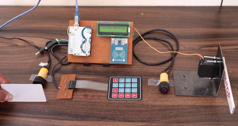
Now when the Vehicle crosses the first IR Sensor, it will display a Vehicle Detected message. Then the system will ask you to scan the RFID Card so that you can go ahead.
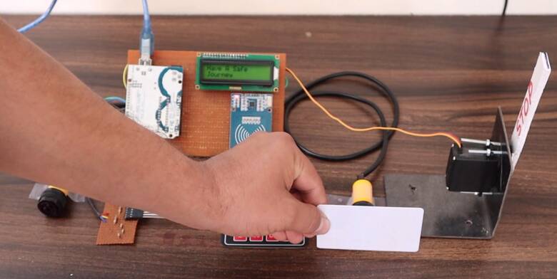
Now you can scan the RFID Card for your Vehicle. The system will deduct 500 from the balance on your RFID Card. The LCD will display Bill Successfully paid message.
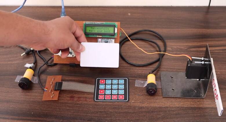
The amount of balance remaining in your RFID Card will be shown by the LCD Display at the same time.
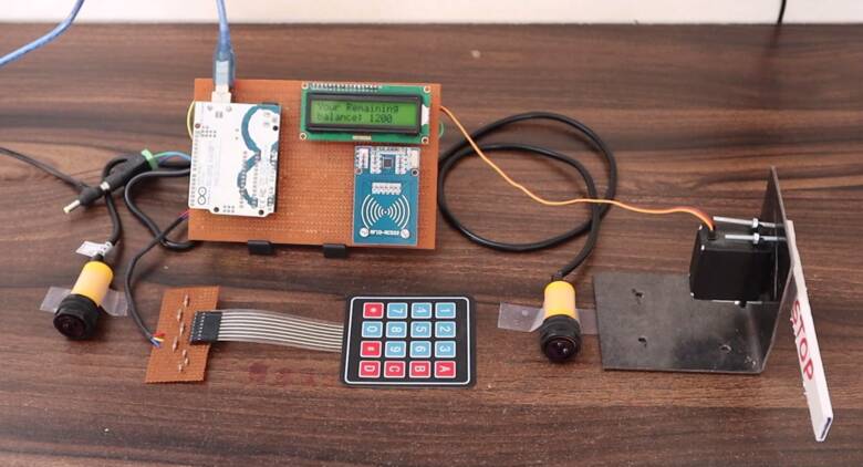
Now your bill is paid. So, you can go ahead now. The the LCD will display a Safe journey Message and this is how the Automated Toll Collection System using RFID & Arduino works.
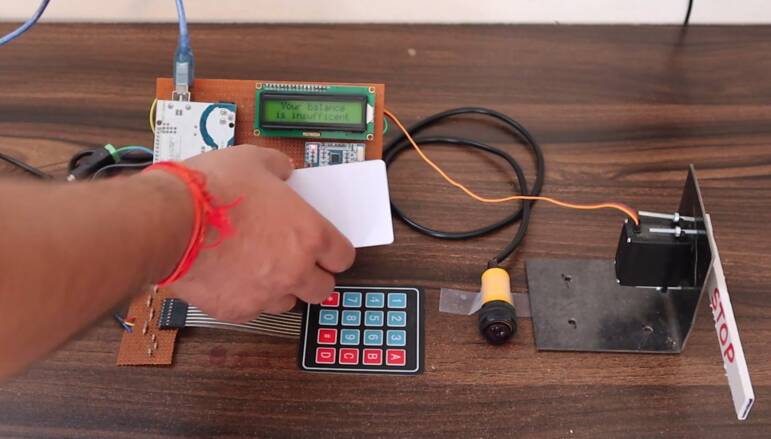
You can repeat the same process again with another RFID. Consider the RFID has only a 200 balance and the amount that is need to be paid is 500. In this case, if you scan the card, the LCD Display will show Insufficient Balance.
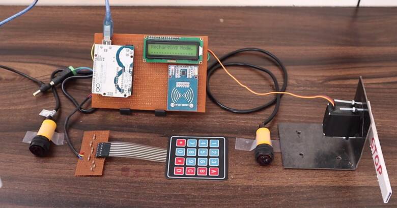
Therefore you need to recharge the RFID Card and load some balance. To do that press the ‘A’ Button on Keypad. The System will now go into recharging mode.
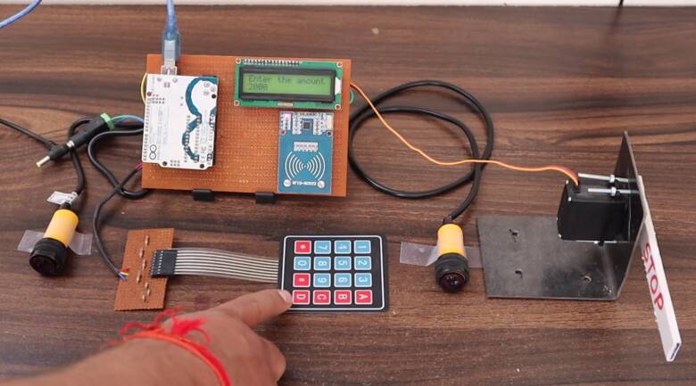
Now you can enter the amount you need to load into your RFID Card. For example, after entering 2000 from the Keypad, you can press ‘D’ to confirm. Now your card will have a 2000 balance added to the previous balance.
Thus this is how the entire system works and you can use this system to repeat the process again and again.
Video Tutorial & Guide


")


3 Comments
code isnt there, please upload
good day please how can i modify the code so that i can type the amount to be deducted from the rfid card instead of automatic deduction
Do you think we can add GSM module to the sytem to send data to a mobile Device?