

Overview: Control Home Appliances using LoRa Relay Switch
In this project, we will make a LoRa Relay Switch or LoRa Based Power Relay Control System using Arduino & RFM98 LoRa Module. The LoRa Relay Node will able able to transmit the data to Gateway. We can press the switch button on Sender or LoRa Node side which can turn OFF/ON the relay remotely.
The LoRa Relay Power Switch is a smart LoRa device for remotely controlling industrial and home appliances remotely. The Remote Power Switch can be used to remotely control the power of external devices or appliances. Appliances include the control of general devices, lighting, irrigation systems, pumps, remote servers, towers, enabling and disabling security systems, access control of gates and doors.
Communication with the Remote Power Switch is done using the integrated loRaWAN module. All you need to do is upload the code using Micro-USB port, connect to your LoRaWAN network, connect the Remote Power Switch to your power outlet, and connect your appliances to the Remote Power Switch.

Before getting started with this project, you can check our previous LoRa Based Projects, which will clear your all concepts of LoRaWAN Technology.
Bill of Materials
Following are the components required for making this project. All the components can be easily purchased from Amazon. The component purchase link is given below.
| S.N. | Components Name | Quantity | Purchase Link |
|---|---|---|---|
| 1 | LoRa Relay Switch | 1 | Makerfabs |
| 2 | LoRa Receiver | 1 | Makerfabs |
| 3 | USB-to-UART Converter | 1 | Makerfabs |
| 4 | 0.96" I2C OLED Display | 1 | Amazon | AliExpress |
| 5 | Push Button Switch | 1 | Amazon | AliExpress |
| 6 | AC Bulb | 1 | - |
| 7 | Electric Wires | 1-2 meter | - |
| 8 | Jumper Wires | 10 | Amazon | AliExpress |
| 9 | Micro-USB Cable | 1 | Amazon | AliExpress |
LoRa Relay Module 30A
This 30A Lora Relay Node or Switch is a relay module that could be controlled by Lora, with max current 30A/240V. Based on LoRa Module RFM98W, it supports max 4~5 km Lora communication.

This Lora relay module is preloaded Arduino Pro Mini(3.3v 8M) bootloader and simple demo firmware Lora Relay V1.1, the users could freely change/update the firmware with Arduino IDE, with a common UART tool.
Features
- Controller: Atmega328P
- Arduino bootloader: Pro mini(3.3V/8M)
- Lora frequency: 433M/ 868M/ 915M
- Current: 30A@240VAC
- Input Voltage: 12V
LoRa Receiver: Lora Radio (433M/868M/915M)
The Lora Radio Receiver is a mainboard based on the ATmega328 and 433MHZ/868MHz/915MHz RFM95 LoRa module. The LoRa Radio allows the user to send data and reach extremely long ranges at low data-rates. It provides ultra-long range spread spectrum communication and high interference immunity whilst minimizing current consumption. It has Arduino pro mini 3.3V 8MHz bootloader on this board and uses the CP2104 as USB to serial to upload the code using Arduino IDE. In this Lora Relay Control project, we will use it as a Receiver Gateway.

Features
- BAT Input Voltage: 3.4-4.2V
- Integrated Power Control System
- 127 dB Dynamic Range RSSI
- Uses the License-free ISM band: “European ISM” @ 433MHz/868MHz/915MHz
- +5 to +20 dBm up to 100 mW Power Output Capability (power output selectable in software)
- ~100mA Peak during +20dBm transmit, ~30mA during active radio listening
- Range of approx. 2Km, depending on obstructions, frequency, antenna, and power output
Setting Up LoRa Relay Receiver
The Lora Power Relay can be used to switch the AC bulb light on or off. I integrated the 30A current relay, which will give you a wide use for the large current devices.
For the demonstration process I use a bulb and connected to the output of the Relay. The device can be powered up either using a 12V Adapter or a 12V Battery. Here is a circuit diagram of the entire connection.

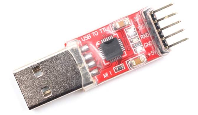
In order to upload code to the microcontroller, we need a USB-to-TTL or a FTDI Module.
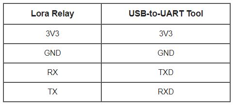
Make a connection between Lora Relay Module and FTDI as shown in the table below.
So the complete connection and setup can be done as shown in the image below.

Setting Up LoRa Sender/Controller
Now let us setup the receiver now. The Receiver module has two extra connections. We need to connect a 0.96″ I2C OLED Display and a Push Button Switch.

The Assembly of the circuit can be either done in a breadboard or it can be done using a Custom design PCB.

LoRa Relay Receiver Code
The Receiver Controller Code that need to uploaded to LoRa Relay Node is given below.
The code requires a LoRa Library to compile. So download the LoRa Library and add it to the Arduino IDE.
|
1 2 3 4 5 6 7 8 9 10 11 12 13 14 15 16 17 18 19 20 21 22 23 24 25 26 27 28 29 30 31 32 33 34 35 36 37 38 39 40 41 42 43 44 45 46 47 48 49 50 51 52 53 54 55 56 57 58 59 60 61 62 63 64 65 66 67 68 69 70 71 72 73 74 75 76 77 78 79 80 81 82 83 84 85 86 87 88 89 90 91 92 93 94 95 96 97 98 99 100 101 102 103 104 105 106 107 108 |
//Libraries for LoRa #include <SPI.h> #include <LoRa.h> //define the pins used by the LoRa transceiver module #define ss 10 #define rst 9 #define dio0 2 #define LED 5 #define RELAY_IO 4 #define BAND 433E6 //433E6 for Asia, 866E6 for Europe, 915E6 for North America // Initialize variables to get and save LoRa data int rssi; int relayswitch; String status; String readingID; // Replaces placeholder with RElay values String processor(const String& var) { //Serial.println(var); if(var == "STATUS") { return status; } else if (var == "RRSI") { return String(rssi); } return String(); } void setup() { Serial.begin(115200); pinMode(RELAY_IO, OUTPUT); pinMode(LED, OUTPUT); int counter; //setup LoRa transceiver module LoRa.setPins(ss, rst, dio0); //setup LoRa transceiver module while (!LoRa.begin(BAND) && counter < 10) { Serial.print("."); counter++; delay(2000); } if (counter == 10) { // Increment readingID on every new reading Serial.println("Starting LoRa failed!"); } Serial.println("LoRa Initialization OK!"); delay(2000); } // Read LoRa packet and get the sensor readings void loop() { int packetSize = LoRa.parsePacket(); if (packetSize) { Serial.print("Lora packet received: "); while (LoRa.available()) // Read packet { String LoRaData = LoRa.readString(); Serial.print(LoRaData); int pos1 = LoRaData.indexOf('&'); readingID = LoRaData.substring(0, pos1); // Get readingID status = LoRaData.substring(pos1 +1, LoRaData.length()); // Get status relayswitch = status.toInt(); //Converts string to integer if(relayswitch==1) { digitalWrite (RELAY_IO, relayswitch); digitalWrite (LED, relayswitch); Serial.println("Realy in ON"); } else if(relayswitch==0) { digitalWrite (RELAY_IO, relayswitch); digitalWrite (LED, relayswitch); Serial.println("Realy in OFF"); } } rssi = LoRa.packetRssi(); // Get RSSI Serial.print(" with RSSI "); Serial.println(rssi); } } |
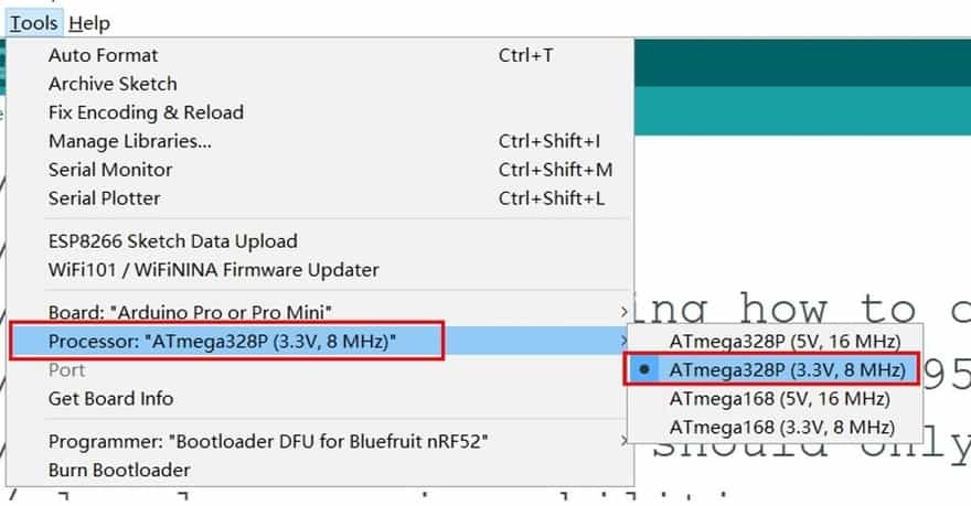
In order to upload the code, from the top Arduino IDE menu, select Tools-> Board-> Arduino Pro or Pro Mini. Then select the correct COM Port and click the upload button.
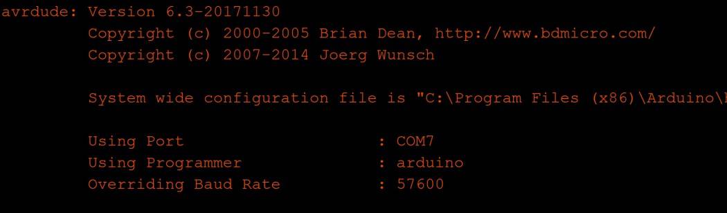
If you upload the firmware fails, press and hold the Reset button before uploading the firmware. When the IDE shows below, then release the button that may help to upload the firmware success. That’s we need a reset the MCU when uploading the firmware.
LoRa Sender/Controller Code
The LoRa Sender code for Controlling LoRa Relay Wirelessly is given below. Before uploading code you need to install the OLED Library first along with the LoRa Library.
|
1 2 3 4 5 6 7 8 9 10 11 12 13 14 15 16 17 18 19 20 21 22 23 24 25 26 27 28 29 30 31 32 33 34 35 36 37 38 39 40 41 42 43 44 45 46 47 48 49 50 51 52 53 54 55 56 57 58 59 60 61 62 63 64 65 66 67 68 69 70 71 72 73 74 75 76 77 78 79 80 81 82 83 84 85 86 87 88 89 90 91 92 93 94 95 96 97 98 99 100 101 102 103 104 105 106 107 108 109 110 111 112 113 114 115 116 117 118 119 120 121 122 123 124 125 126 127 128 129 130 131 132 133 134 135 136 137 138 139 140 141 142 143 144 145 146 147 148 149 150 151 152 153 154 155 156 157 158 159 160 161 162 163 164 165 166 167 168 169 170 171 172 173 174 175 176 177 178 179 180 181 182 183 184 185 186 187 188 189 190 191 192 193 194 195 196 197 198 199 200 201 202 203 204 205 206 207 208 209 210 211 212 213 214 215 216 217 218 219 220 221 222 223 224 225 226 227 228 229 230 231 232 233 234 235 |
//Libraries for LoRa #include <SPI.h> #include <Wire.h> #include <LoRa.h> #include <Adafruit_GFX.h> #include <Adafruit_SSD1306.h> #define SCREEN_WIDTH 128 // OLED display width, in pixels #define SCREEN_HEIGHT 64 // OLED display height, in pixels #define OLED_RESET 4 // Reset pin # (or -1 if sharing Arduino reset pin) Adafruit_SSD1306 display(SCREEN_WIDTH, SCREEN_HEIGHT, &Wire, OLED_RESET); #define LOGO_HEIGHT 53 #define LOGO_WIDTH 128 static const unsigned char PROGMEM logo_ON[] = { 0x87, 0x87, 0x87, 0xff, /*Color of index 0*/ 0xf8, 0xf9, 0xf8, 0xff, /*Color of index 1*/ 0xff, 0xff, 0xff, 0xff, 0xff, 0xff, 0xff, 0xff, 0xff, 0xff, 0xff, 0xff, 0xff, 0xff, 0xff, 0xff, 0xff, 0xff, 0xff, 0xff, 0xff, 0xff, 0xff, 0xff, 0xff, 0xff, 0xff, 0xff, 0xff, 0xff, 0xff, 0xff, 0xff, 0xff, 0xf0, 0x00, 0x00, 0x00, 0x00, 0x00, 0x00, 0x00, 0x00, 0x00, 0x00, 0x0f, 0xff, 0xff, 0xff, 0xff, 0x00, 0x00, 0x00, 0x00, 0x00, 0x00, 0x00, 0x00, 0x00, 0x00, 0x0f, 0xf8, 0xff, 0xff, 0xff, 0xfc, 0x00, 0x00, 0x00, 0x00, 0x00, 0x00, 0x00, 0x00, 0x00, 0x00, 0xff, 0xff, 0x3f, 0xff, 0xff, 0xf0, 0x00, 0x00, 0x00, 0x00, 0x00, 0x00, 0x00, 0x00, 0x00, 0x03, 0xff, 0xff, 0xcf, 0xff, 0xff, 0xc0, 0x00, 0x00, 0x00, 0x00, 0x00, 0x00, 0x00, 0x00, 0x00, 0x0f, 0xff, 0xff, 0xf3, 0xff, 0xff, 0x80, 0x00, 0x00, 0x00, 0x00, 0x00, 0x00, 0x00, 0x00, 0x00, 0x3f, 0xff, 0xff, 0xfd, 0xff, 0xff, 0x00, 0x00, 0x00, 0x00, 0x00, 0x00, 0x00, 0x00, 0x00, 0x00, 0x7f, 0xff, 0xff, 0xfe, 0xff, 0xfe, 0x00, 0x00, 0x00, 0x00, 0x00, 0x00, 0x00, 0x00, 0x00, 0x00, 0xff, 0xff, 0xff, 0xff, 0x7f, 0xfc, 0x00, 0x00, 0x00, 0x00, 0x00, 0x00, 0x00, 0x00, 0x00, 0x01, 0xff, 0xff, 0xff, 0xff, 0xbf, 0xf8, 0x00, 0x00, 0x00, 0x00, 0x00, 0x00, 0x00, 0x00, 0x00, 0x03, 0xff, 0xff, 0xff, 0xff, 0xdf, 0xf0, 0x00, 0x00, 0x00, 0x00, 0xc0, 0x00, 0x00, 0x00, 0x00, 0x07, 0xff, 0xff, 0xff, 0xff, 0xef, 0xf0, 0x00, 0x00, 0x00, 0x03, 0xf0, 0x78, 0x70, 0x00, 0x00, 0x07, 0xff, 0xff, 0xff, 0xff, 0xef, 0xe0, 0x00, 0x00, 0x00, 0x07, 0xf8, 0x78, 0x78, 0x00, 0x00, 0x0f, 0xff, 0xff, 0xff, 0xff, 0xf7, 0xe0, 0x00, 0x00, 0x00, 0x0f, 0xfc, 0x78, 0x78, 0x00, 0x00, 0x0f, 0xff, 0xff, 0xff, 0xff, 0xff, 0xc0, 0x00, 0x00, 0x00, 0x0f, 0x7c, 0x78, 0x78, 0x00, 0x00, 0x1f, 0xff, 0xff, 0xff, 0xff, 0xfb, 0xc0, 0x00, 0x00, 0x00, 0x0f, 0x3c, 0x7c, 0x78, 0x00, 0x00, 0x1f, 0xff, 0xff, 0xff, 0xff, 0xff, 0x80, 0x00, 0x00, 0x00, 0x0f, 0x3c, 0x7c, 0x78, 0x00, 0x00, 0x3f, 0xff, 0xff, 0xff, 0xff, 0xfd, 0x80, 0x00, 0x00, 0x00, 0x0f, 0x3c, 0x7c, 0x78, 0x00, 0x00, 0x3f, 0xff, 0xff, 0xff, 0xff, 0xfd, 0x80, 0x00, 0x00, 0x00, 0x0f, 0x3c, 0x7e, 0x78, 0x00, 0x00, 0x3f, 0xff, 0xff, 0xff, 0xff, 0xff, 0x00, 0x00, 0x00, 0x00, 0x0f, 0x3c, 0x7e, 0x78, 0x00, 0x00, 0x7f, 0xff, 0xff, 0xff, 0xff, 0xfe, 0x00, 0x00, 0x00, 0x00, 0x0f, 0x3c, 0x7e, 0x78, 0x00, 0x00, 0x7f, 0xff, 0xff, 0xff, 0xff, 0xfe, 0x00, 0x00, 0x00, 0x00, 0x0f, 0x3c, 0x7e, 0x78, 0x00, 0x00, 0x7f, 0xff, 0xff, 0xff, 0xff, 0xfe, 0x00, 0x00, 0x00, 0x00, 0x0f, 0x3c, 0x7f, 0x78, 0x00, 0x00, 0x7f, 0xff, 0xff, 0xff, 0xff, 0xfe, 0x00, 0x00, 0x00, 0x00, 0x0f, 0x3c, 0x7f, 0x78, 0x00, 0x00, 0x7f, 0xff, 0xff, 0xff, 0xff, 0xfe, 0x00, 0x00, 0x00, 0x00, 0x0f, 0x3c, 0x7f, 0x78, 0x00, 0x00, 0x7f, 0xff, 0xff, 0xff, 0xff, 0xfe, 0x00, 0x00, 0x00, 0x00, 0x0f, 0x3c, 0x7b, 0xf8, 0x00, 0x00, 0x7f, 0xff, 0xff, 0xff, 0xff, 0xfe, 0x00, 0x00, 0x00, 0x00, 0x0f, 0x3c, 0x7b, 0xf8, 0x00, 0x00, 0x7f, 0xff, 0xff, 0xff, 0xff, 0xfe, 0x00, 0x00, 0x00, 0x00, 0x0f, 0x3c, 0x7b, 0xf8, 0x00, 0x00, 0x7f, 0xff, 0xff, 0xff, 0xff, 0xfe, 0x00, 0x00, 0x00, 0x00, 0x0f, 0x3c, 0x7b, 0xf8, 0x00, 0x00, 0x7f, 0xff, 0xff, 0xff, 0xff, 0xfe, 0x00, 0x00, 0x00, 0x00, 0x0f, 0x3c, 0x79, 0xf8, 0x00, 0x00, 0x7f, 0xff, 0xff, 0xff, 0xff, 0xff, 0x80, 0x00, 0x00, 0x00, 0x0f, 0x3c, 0x79, 0xf8, 0x00, 0x00, 0x3f, 0xff, 0xff, 0xff, 0xff, 0xfd, 0x80, 0x00, 0x00, 0x00, 0x0f, 0x3c, 0x79, 0xf8, 0x00, 0x00, 0x3f, 0xff, 0xff, 0xff, 0xff, 0xfd, 0x80, 0x00, 0x00, 0x00, 0x0f, 0x3c, 0x79, 0xf8, 0x00, 0x00, 0x3f, 0xff, 0xff, 0xff, 0xff, 0xff, 0xc0, 0x00, 0x00, 0x00, 0x0f, 0x3c, 0x78, 0xf8, 0x00, 0x00, 0x1f, 0xff, 0xff, 0xff, 0xff, 0xfb, 0xc0, 0x00, 0x00, 0x00, 0x0f, 0xfc, 0x78, 0xf8, 0x00, 0x00, 0x1f, 0xff, 0xff, 0xff, 0xff, 0xfb, 0xe0, 0x00, 0x00, 0x00, 0x0f, 0xf8, 0x78, 0xf8, 0x00, 0x00, 0x0f, 0xff, 0xff, 0xff, 0xff, 0xf7, 0xe0, 0x00, 0x00, 0x00, 0x07, 0xf8, 0x78, 0x78, 0x00, 0x00, 0x0f, 0xff, 0xff, 0xff, 0xff, 0xf7, 0xf0, 0x00, 0x00, 0x00, 0x03, 0xf0, 0x78, 0x70, 0x00, 0x00, 0x07, 0xff, 0xff, 0xff, 0xff, 0xef, 0xf8, 0x00, 0x00, 0x00, 0x00, 0x00, 0x00, 0x00, 0x00, 0x00, 0x03, 0xff, 0xff, 0xff, 0xff, 0xff, 0xf8, 0x00, 0x00, 0x00, 0x00, 0x00, 0x00, 0x00, 0x00, 0x00, 0x03, 0xff, 0xff, 0xff, 0xff, 0xff, 0xfc, 0x00, 0x00, 0x00, 0x00, 0x00, 0x00, 0x00, 0x00, 0x00, 0x01, 0xff, 0xff, 0xff, 0xff, 0xbf, 0xfe, 0x00, 0x00, 0x00, 0x00, 0x00, 0x00, 0x00, 0x00, 0x00, 0x00, 0xff, 0xff, 0xff, 0xff, 0x7f, 0xff, 0x00, 0x00, 0x00, 0x00, 0x00, 0x00, 0x00, 0x00, 0x00, 0x00, 0x7f, 0xff, 0xff, 0xfe, 0xff, 0xff, 0xc0, 0x00, 0x00, 0x00, 0x00, 0x00, 0x00, 0x00, 0x00, 0x00, 0x1f, 0xff, 0xff, 0xfb, 0xff, 0xff, 0xe0, 0x00, 0x00, 0x00, 0x00, 0x00, 0x00, 0x00, 0x00, 0x00, 0x0f, 0xff, 0xff, 0xf7, 0xff, 0xff, 0xf8, 0x00, 0x00, 0x00, 0x00, 0x00, 0x00, 0x00, 0x00, 0x00, 0x03, 0xff, 0xff, 0xdf, 0xff, 0xff, 0xfe, 0x00, 0x00, 0x00, 0x00, 0x00, 0x00, 0x00, 0x00, 0x00, 0x00, 0x7f, 0xff, 0x7f, 0xff, 0xff, 0xff, 0xc0, 0x00, 0x00, 0x00, 0x00, 0x00, 0x00, 0x00, 0x00, 0x00, 0x07, 0xf3, 0xff, 0xff, 0xff, 0xff, 0xff, 0xff, 0xff, 0xff, 0xff, 0xff, 0xff, 0xff, 0xff, 0xff, 0xff, 0xff, 0xff, 0xff, 0xff, 0xff, 0xff, 0xff, 0xff, 0xff, 0xff, 0xff, 0xff, 0xff, 0xff, 0xff, 0xff, 0xff, 0xff, 0xff, 0xff, 0xff, 0xff, 0xff, 0xff, 0xff, 0xff, 0xff, 0xff, 0xff, 0xff, 0xff, 0xff, 0xff, 0xff, 0xff, }; static const unsigned char PROGMEM logo_OFF[] = { 0x3b, 0x3b, 0x3b, 0xff, /*Color of index 0*/ 0xf6, 0xf8, 0xf6, 0xff, /*Color of index 1*/ 0xff, 0xff, 0xff, 0xff, 0xff, 0xff, 0xff, 0xff, 0xff, 0xff, 0xff, 0xff, 0xff, 0xff, 0xff, 0xff, 0xff, 0xff, 0xff, 0xff, 0xff, 0xff, 0xff, 0xff, 0xff, 0xff, 0xff, 0xff, 0xff, 0xff, 0xff, 0xff, 0xff, 0xff, 0xfc, 0x00, 0x00, 0x00, 0x00, 0x00, 0x00, 0x00, 0x00, 0x00, 0x00, 0x3f, 0xff, 0xff, 0xff, 0xff, 0x87, 0xe0, 0x00, 0x00, 0x00, 0x00, 0x00, 0x00, 0x00, 0x00, 0x00, 0x01, 0xff, 0xff, 0xff, 0xfc, 0x7f, 0xff, 0x00, 0x00, 0x00, 0x00, 0x00, 0x00, 0x00, 0x00, 0x00, 0x00, 0x3f, 0xff, 0xff, 0xf3, 0xff, 0xff, 0xc0, 0x00, 0x00, 0x00, 0x00, 0x00, 0x00, 0x00, 0x00, 0x00, 0x0f, 0xff, 0xff, 0xef, 0xff, 0xff, 0xf0, 0x00, 0x00, 0x00, 0x00, 0x00, 0x00, 0x00, 0x00, 0x00, 0x07, 0xff, 0xff, 0x9f, 0xff, 0xff, 0xf8, 0x00, 0x00, 0x00, 0x00, 0x00, 0x00, 0x00, 0x00, 0x00, 0x01, 0xff, 0xff, 0x7f, 0xff, 0xff, 0xfe, 0x00, 0x00, 0x00, 0x00, 0x00, 0x00, 0x00, 0x00, 0x00, 0x00, 0xff, 0xfe, 0xff, 0xff, 0xff, 0xff, 0x00, 0x00, 0x00, 0x00, 0x00, 0x00, 0x00, 0x00, 0x00, 0x00, 0x7f, 0xfd, 0xff, 0xff, 0xff, 0xff, 0x80, 0x00, 0x00, 0x00, 0x00, 0x00, 0x00, 0x00, 0x00, 0x00, 0x3f, 0xfb, 0xff, 0xff, 0xff, 0xff, 0xc0, 0x00, 0x00, 0x00, 0x00, 0x00, 0x00, 0x00, 0x00, 0x00, 0x1f, 0xf3, 0xff, 0xff, 0xff, 0xff, 0xe0, 0x00, 0x00, 0x00, 0x00, 0x00, 0x00, 0x00, 0x00, 0x00, 0x0f, 0xf7, 0xff, 0xff, 0xff, 0xff, 0xe0, 0x00, 0x00, 0x1f, 0x83, 0xff, 0x7f, 0xe0, 0x00, 0x00, 0x0f, 0xef, 0xff, 0xff, 0xff, 0xff, 0xf0, 0x00, 0x00, 0x3f, 0xc3, 0xff, 0x7f, 0xe0, 0x00, 0x00, 0x07, 0xef, 0xff, 0xff, 0xff, 0xff, 0xf0, 0x00, 0x00, 0x3f, 0xe3, 0xff, 0x7f, 0xe0, 0x00, 0x00, 0x07, 0xdf, 0xff, 0xff, 0xff, 0xff, 0xf8, 0x00, 0x00, 0x7f, 0xe3, 0xff, 0x7f, 0xe0, 0x00, 0x00, 0x03, 0xdf, 0xff, 0xff, 0xff, 0xff, 0xf8, 0x00, 0x00, 0x79, 0xe3, 0xc0, 0x78, 0x00, 0x00, 0x00, 0x03, 0xbf, 0xff, 0xff, 0xff, 0xff, 0xfc, 0x00, 0x00, 0x78, 0xf3, 0xc0, 0x78, 0x00, 0x00, 0x00, 0x01, 0xbf, 0xff, 0xff, 0xff, 0xff, 0xfc, 0x00, 0x00, 0x78, 0xf3, 0xc0, 0x78, 0x00, 0x00, 0x00, 0x01, 0xbf, 0xff, 0xff, 0xff, 0xff, 0xfc, 0x00, 0x00, 0x78, 0xf3, 0xc0, 0x78, 0x00, 0x00, 0x00, 0x01, 0x7f, 0xff, 0xff, 0xff, 0xff, 0xfe, 0x00, 0x00, 0x78, 0xf3, 0xc0, 0x78, 0x00, 0x00, 0x00, 0x00, 0x7f, 0xff, 0xff, 0xff, 0xff, 0xfe, 0x00, 0x00, 0x78, 0xf3, 0xc0, 0x78, 0x00, 0x00, 0x00, 0x00, 0x7f, 0xff, 0xff, 0xff, 0xff, 0xfe, 0x00, 0x00, 0x78, 0xf3, 0xc0, 0x78, 0x00, 0x00, 0x00, 0x00, 0x7f, 0xff, 0xff, 0xff, 0xff, 0xfe, 0x00, 0x00, 0x78, 0xf3, 0xfc, 0x7f, 0x80, 0x00, 0x00, 0x00, 0x7f, 0xff, 0xff, 0xff, 0xff, 0xfe, 0x00, 0x00, 0x78, 0xf3, 0xfc, 0x7f, 0x80, 0x00, 0x00, 0x00, 0x7f, 0xff, 0xff, 0xff, 0xff, 0xfe, 0x00, 0x00, 0x78, 0xf3, 0xfc, 0x7f, 0x80, 0x00, 0x00, 0x00, 0x7f, 0xff, 0xff, 0xff, 0xff, 0xfe, 0x00, 0x00, 0x78, 0xf3, 0xfc, 0x7f, 0x80, 0x00, 0x00, 0x00, 0x7f, 0xff, 0xff, 0xff, 0xff, 0xfe, 0x00, 0x00, 0x78, 0xf3, 0xe0, 0x7c, 0x00, 0x00, 0x00, 0x00, 0x7f, 0xff, 0xff, 0xff, 0xff, 0xfe, 0x00, 0x00, 0x78, 0xf3, 0xc0, 0x78, 0x00, 0x00, 0x00, 0x00, 0x7f, 0xff, 0xff, 0xff, 0xff, 0xfe, 0x00, 0x00, 0x78, 0xf3, 0xc0, 0x78, 0x00, 0x00, 0x00, 0x00, 0x7f, 0xff, 0xff, 0xff, 0xff, 0xfe, 0x00, 0x00, 0x78, 0xf3, 0xc0, 0x78, 0x00, 0x00, 0x00, 0x00, 0xbf, 0xff, 0xff, 0xff, 0xff, 0xfc, 0x00, 0x00, 0x78, 0xf3, 0xc0, 0x78, 0x00, 0x00, 0x00, 0x01, 0xbf, 0xff, 0xff, 0xff, 0xff, 0xfc, 0x00, 0x00, 0x78, 0xf3, 0xc0, 0x78, 0x00, 0x00, 0x00, 0x01, 0xbf, 0xff, 0xff, 0xff, 0xff, 0xfc, 0x00, 0x00, 0x78, 0xf3, 0xc0, 0x78, 0x00, 0x00, 0x00, 0x01, 0xdf, 0xff, 0xff, 0xff, 0xff, 0xf8, 0x00, 0x00, 0x79, 0xe3, 0xc0, 0x78, 0x00, 0x00, 0x00, 0x03, 0xdf, 0xff, 0xff, 0xff, 0xff, 0xf8, 0x00, 0x00, 0x7f, 0xe3, 0xc0, 0x78, 0x00, 0x00, 0x00, 0x03, 0xef, 0xff, 0xff, 0xff, 0xff, 0xf8, 0x00, 0x00, 0x3f, 0xe3, 0xc0, 0x78, 0x00, 0x00, 0x00, 0x07, 0xef, 0xff, 0xff, 0xff, 0xff, 0xf0, 0x00, 0x00, 0x3f, 0xc3, 0xc0, 0x78, 0x00, 0x00, 0x00, 0x07, 0xf7, 0xff, 0xff, 0xff, 0xff, 0xe0, 0x00, 0x00, 0x1f, 0x83, 0xc0, 0x78, 0x00, 0x00, 0x00, 0x0f, 0xf3, 0xff, 0xff, 0xff, 0xff, 0xe0, 0x00, 0x00, 0x00, 0x00, 0x00, 0x00, 0x00, 0x00, 0x00, 0x0f, 0xfb, 0xff, 0xff, 0xff, 0xff, 0xc0, 0x00, 0x00, 0x00, 0x00, 0x00, 0x00, 0x00, 0x00, 0x00, 0x1f, 0xfd, 0xff, 0xff, 0xff, 0xff, 0x80, 0x00, 0x00, 0x00, 0x00, 0x00, 0x00, 0x00, 0x00, 0x00, 0x3f, 0xfe, 0xff, 0xff, 0xff, 0xff, 0x00, 0x00, 0x00, 0x00, 0x00, 0x00, 0x00, 0x00, 0x00, 0x00, 0x7f, 0xff, 0x7f, 0xff, 0xff, 0xfe, 0x00, 0x00, 0x00, 0x00, 0x00, 0x00, 0x00, 0x00, 0x00, 0x00, 0xff, 0xff, 0x9f, 0xff, 0xff, 0xfc, 0x00, 0x00, 0x00, 0x00, 0x00, 0x00, 0x00, 0x00, 0x00, 0x01, 0xff, 0xff, 0xef, 0xff, 0xff, 0xf0, 0x00, 0x00, 0x00, 0x00, 0x00, 0x00, 0x00, 0x00, 0x00, 0x07, 0xff, 0xff, 0xf3, 0xff, 0xff, 0xc0, 0x00, 0x00, 0x00, 0x00, 0x00, 0x00, 0x00, 0x00, 0x00, 0x0f, 0xff, 0xff, 0xfc, 0xff, 0xff, 0x00, 0x00, 0x00, 0x00, 0x00, 0x00, 0x00, 0x00, 0x00, 0x00, 0x3f, 0xff, 0xff, 0xff, 0x8f, 0xf0, 0x00, 0x00, 0x00, 0x00, 0x00, 0x00, 0x00, 0x00, 0x00, 0x01, 0xff, 0xff, 0xff, 0xff, 0xfc, 0x00, 0x00, 0x00, 0x00, 0x00, 0x00, 0x00, 0x00, 0x00, 0x00, 0x3f, 0xff, 0xff, 0xff, 0xff, 0xff, 0xff, 0xff, 0xff, 0xff, 0xff, 0xff, 0xff, 0xff, 0xff, 0xff, 0xff, 0xff, 0xff, 0xff, 0xff, 0xff, 0xff, 0xff, 0xff, 0xff, 0xff, 0xff, 0xff, 0xff, 0xff, 0xff, 0xff, 0xff, 0xff, }; //define the pins used by the LoRa transceiver module #define ss 10 #define rst 9 #define dio0 2 #define BAND 433E6 //433E6 for Asia, 866E6 for Europe, 915E6 for North America int button = 3; //Push Button int status = false; int rssi; //packet counter int readingID = 0; int counter = 0; String LoRaMessage = ""; void setup() { //initialize Serial Monitor Serial.begin(115200); display.begin(SSD1306_SWITCHCAPVCC, 0x3C); //initialize with the I2C addr 0x3C (128x64) pinMode(button, INPUT_PULLUP); LoRa.setPins(ss, rst, dio0); //setup LoRa transceiver module while (!LoRa.begin(BAND) && counter < 10) { Serial.print("."); counter++; delay(500); } if (counter == 10) { // Increment readingID on every new reading readingID++; Serial.println("Starting LoRa failed!"); display.clearDisplay(); display.setCursor(0,0); display.setTextSize(1); display.setTextColor(WHITE); display.println("LoRa Initialization"); display.println(""); display.setTextSize(2); display.println("Failed! "); display.display(); } Serial.println("LoRa Initialization OK!"); display.clearDisplay(); display.setCursor(0,0); display.setTextSize(1); display.setTextColor(WHITE); display.println("LoRa Initialization"); display.println(" "); display.setTextSize(2); display.println("OK! "); display.display(); delay(3000); } void loop() { if (digitalRead(button) == true) { status = !status; } while(digitalRead(button) == true); LoRaMessage = String(readingID) + "&" + String(status) ; //Send LoRa packet to receiver LoRa.beginPacket(); LoRa.print(LoRaMessage); readingID++; rssi = LoRa.packetRssi(); // Get RSSI Serial.print("Sending packet: "); Serial.println(readingID); Serial.println(LoRaMessage); LoRa.endPacket(); if(status==1) { display.clearDisplay(); display.drawBitmap(0, 8, logo_ON, LOGO_WIDTH, LOGO_HEIGHT, 1); display.display(); } else if(status==0) { display.clearDisplay(); display.drawBitmap(0, 8, logo_OFF, LOGO_WIDTH, LOGO_HEIGHT, 1); display.display(); } delay(300); } |
For uploading code select the select Tools-> Board-> Arduino Pro or Pro Mini. Then select the correct COM Port and click the upload button.
Control Home Appliances using LoRa Relay Switch
After setting up and uploading the code in both the LoRa Node & Gateway, you can now check the working of the device. Power ON both the circuit and then strat testing.
When you press the push button on the Sender side the Relay gets activated and Bulb turns ON.

When you press the push button once again on the Sender side the Relay gets disconnected and Bulb turns OFF.

Video Tutorial & Guide


3 Comments
Good Day,
I am trying to modify your code to allow for a solid sate switch. In other words, when DIO 3 is high then relay on and if DIO 3 Low then relay off. Please can you assist me as I only seam to “flash” the light with no control. I know I have done something wrong.
Thank you
Hi, for how long you have tested your device. I mean by lora connectivity.
I have made a similar circuit for testing the lora connectivity(point to point communication) using leds but the connectivity sustain only for 3 days after that lora communication is getting disconnected. Even i tried rebooting the controller to setup the connection again but it getting connected again between 1 to 7 times of reboot. Have you faced this issue of lora getting disconnected any time during testing of your project? if yes, then how you solved it?
I didn’t face any such issue. But you can implement watch dog timer reset or a periodic automatic reset after every 30 minutes. This might fix the issue.