

Introduction to LM386 Audio Amplifier IC
LM386 IC is an audio power amplifier integrated circuit designed for use in low voltage consumer applications. It is suitable for battery-powered devices such as radios, doorbells, telephones, guitars amplifiers, and hobby electronic projects. It is mostly used as an amplifier in computer speakers and small portable stereos.
The LM386 IC is available in 8 pins dual in-line package (DIP-8). The voltage gain of the amplifier can be adjusted to 20 and it will be enhanced to 200 by adding external components like resistor and capacitor among the pin 1 and 8. The LM386 IC amplifier consists of 8 pins where pin 1 and pin 8 are gain control pins. This allows a customer to control the volume. Depending on the model, using a 9-volt power supply, an amplifier can deliver the output power in the range of 0.25W to 1W.
In this guide, we will learn about the LM386 Low Voltage Audio Power Amplifier IC basics, features, circuit, working, pins configuration & Applications. You can go through the Op-Amp IC 741 & also LM358 Dual Op-Amp IC to learn more about the operational amplifier.
Features and Specifications
The followings are the main features and specifications of LM386 IC:
- Wide range of supply voltage: 4V-12V or 5 V-18V (Based on model)
- Voltage gain from 20 to 200
- Battery operation
- Minimum external components
- Low static power drain: 4mA
- Available in package of MSOP
- Operating temperature: 0 -70˚C
- Low Distortion :0.2%
- Input is referenced by ground
- Self-concentric output static voltage
- Speaker impedance 4Ω
Electrical Characteristic of LM386 IC
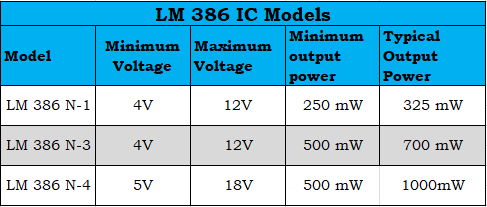
Based on the model, the voltage gain of the IC 386 IC amplifier can vary from 20 to 200 with a supply voltage range of 4V-12V or 5V-18V. There are three models of the audio power amplifier available on market and they are LM386N-1, LM386N-3, and LM386N-4.
The minimum voltage, maximum voltage, minimum output power, and typical output power of the amplifiers associated with these three models are given in the tabular diagram shown below.
LM386 Pins Configuration
The real image and pin-out configuration of LM386 IC are shown in the diagram below. LM386 has eight pins in total which have different functions.

Pin Description
- Pin1 (Gain): It is a gain pin used to adjust the amplifier gain by connecting this IC to an external component capacitor.
- Pin 2 (Input -): It is a non-inverting input terminal used to provide the audio signal.
- Pin 3 (Input +): It is inverting input terminal used to provide the audio signal.
- Pin 4 (GND): It is a ground pin connected to the ground terminal of the system
- Pin 5 (Vout): It is the output pin used to provide amplified output audio, and is allied to the speaker.
- Pin 6 (Vs): It is connected to the power and receives the positive DC voltage.
- Pin 7 (Bypass): It is a bypass pin used to connect a decoupling capacitor.
- Pin 8 (Gain): It is a gain setting pin used to control the gain of the amplifier.
From this pin description, we can say that
- Pin 1 and Pin 8 represent the gain control terminal of the amplifier. These are the terminals where we can adjust the gain by placing a resistor and capacitor or just a capacitor between these terminals.
- Pin 2 and Pin 3 represent the sound input signal terminals. These are the terminals where we place the sound that we want to amplify. Pin 2 is the negative input and Pin 3 is the positive input.
- Pin 4 is GND (ground) Terminal and is connected to the ground in the circuit.
- Pin 5 represents the output of the amplifier. An amplified signal comes out from this terminal.
- Pin 6 receives the positive DC voltage so that the amplifier can receive the necessary power to amplify signals.
- Pin 7 represents the Bypass terminal. This terminal can bypass 15KΩ resistors. it is usually left open or is wired to the ground in circuit design. However, for better stability, a capacitor can be added to the circuit to prevent oscillations in the op-amp IC.
LM386 IC Circuit Diagram and Working
Basically, Audio Amplifier LM 386 includes three functional blocks and they are: Power as well as Output, Bypass, and gain control. The circuit diagram for the audio amplifier using LM 386 IC is shown in the figure below.

The major components of the audio amplifier are LM386 IC, power supply-12V, capacitors like 100 µF, 1000 µF, 0.05 µF, 10 µF, Potentiometer – 10 KΩ, connector, resistor-10 KΩ, speaker-4Ω. These components are connected as per the above circuit diagram.
For the design of this audio amplifier, firstly two power supply pins (pin 4 and pin 6) is connected where pin 4 is given to the ground and pin 6 is connected to a 12V supply. After the power supply, input from any kind of audio source like a mobile phone or microphone is connected through a 3.5 mm connector. The LM 386 IC connects the right and left audio using the source with the ground terminal.
The potentiometer is connected to the input to control the input level in the circuit. Further, a capacitor can be connected to the input in series to remove the DC components.
The gain of this IC is adjusted to 20 and it will be enhanced to 200 by connecting a capacitor (10µF) between pin 1 and pin 8.
We can make a bypass capacitor to reduce the noise by connecting a capacitor (100µF) to pin 7 of LM 386 IC.
At the connection of output, a capacitor (0.05 µF) and a resistor (10 Ω) are connected in series among the GND which is connected to pin 5 of the IC. This circuit form a Zobel network, a filter circuit having a capacitor and resistor and used for adjusting the input impedance.
With the help of impedance, the speaker can be connected in the range of 4 Ω to 32 Ω. Here, the audio amplifier circuit uses a speaker (4 Ω). This speaker can be connected to the capacitor (1000 µF) to remove the unnecessary DC components on the signal.
How to Control Gain for LM386 IC?
The LM 386 IC is designed in such a way that its pin 1 and pin 8 have been attributed with a gain control facility which may be set externally. We can use this facility for a better response of IC.
When the control pins are kept unconnected to anything, the internal resistor (1.35KΩ) sets the gain of the IC to 20. If a capacitor is added across the control pin, the gain will be enhanced to 200.
Hence, The gain of LM 386 IC may be simply made adjustable by connecting a pot in series with a capacitor across pin 1 and pin 8.
Applications of LM386 Audio Amplifier IC
An Audio Amplifier LM 386 IC can be used in a variety of applications. It is one of the most important IC in the audio section, and it is commonly used in the following applications.
- A battery-operated system like TV sound systems, Ultrasonic Drivers, Recording voice from microphone
- AM and FM radio amplifiers
- Low-power audio amplifiers
- Portable music players
- Laptop/computer speakers and small portable stereos
- Audio boosters
- Wien Bridge Oscillator
- Intercoms
- Power converters


1 Comment
Tried this schematics and works quite well. Only, my lm386 gets very hot. Is that normal ? Thanks