

In this project, we will learn how to make IoT based ECG Monitoring System using AD8232 ECG Sensor & NodeMCU ESP8266. We will monitor the ECG waveform/Graph generated from AD8232 Sensor online using an IoT platform called Ubidots.
Overview
Heart diseases are becoming a big issue for the last few decades and many people die because of certain health problems. Therefore, heart disease cannot be taken lightly. So there should be a technology that can monitor the heart rate and heart behavior of the patient regularly. By analyzing or monitoring the ECG signal at the initial stage the various heart disease can be prevented.
This is the reason why I am presenting you with this great IoT project. In this project, I will show you how you can interface AD8232 ECG Sensor with NodeMCU ESP8266 Board and monitor the ECG Waveform on Serial Plotter Screen. Similarly, you can send the ECG waveform over the IoT Cloud platform and monitor the signal online from any part of the world using the PC or simply using the Smartphone. There is no need for staying in the Hospital to monitor heart activity/behavior just because you can monitor it online from anywhere. Thus it can be said advancement in Patient Health Monitoring System.
The IoT platform that I am gonna use here is Ubidots. Ubidots is an IoT Platform empowering innovators and industries to prototype and scale IoT projects to production. Use the Ubidots platform to send data to the cloud from any Internet-enabled device. You can then configure actions and alerts based on your real-time data and unlock the value of your data through visual tools.
You can check my previous post about AD8232 ECG Sensor to learn more about it. It is highly recommended to read the previous post before proceeding for this one:
1. ECG Graph Monitoring with AD8232 ECG Sensor & Arduino
2. IoT Based ECG Monitoring with AD8232 ECG Sensor & ESP32
Components Required
Following are the components that can be used for this project. All the components can be purchased easily from Amazon. The components purchased link is given below.
| S.N. | Components Name | Quantity | Purchase Links |
|---|---|---|---|
| 1 | NodeMCU ESP8266 | 1 | Amazon | AliExpress |
| 2 | AD8232 ECG Sensor | 1 | Amazon | AliExpress |
| 3 | Micro-USB Data Cable | 1 | Amazon | AliExpress |
| 4 | Jumper Wires | Amazon | AliExpress | |
| 5 | Breadboard | 1 | Amazon | AliExpress |
AD8232 ECG Sensor
This sensor is a cost-effective board used to measure the electrical activity of the heart. This electrical activity can be charted as an ECG or Electrocardiogram and output as an analog reading. ECGs can be extremely noisy, the AD8232 Single Lead Heart Rate Monitor acts as an op-amp to help obtain a clear signal from the PR and QT Intervals easily.

The AD8232 is an integrated signal conditioning block for ECG and other biopotential measurement applications. It is designed to extract, amplify, and filter small biopotential signals in the presence of noisy conditions, such as those created by motion or remote electrode placement.
The AD8232 module breaks out nine connections from the IC that you can solder pins, wires, or other connectors to. SDN, LO+, LO-, OUTPUT, 3.3V, GND provide essential pins for operating this monitor with an Arduino or other development board. Also provided on this board are RA (Right Arm), LA (Left Arm), and RL (Right Leg) pins to attach and use your own custom sensors. Additionally, there is an LED indicator light that will pulsate to the rhythm of a heartbeat.
Note: This product is NOT a medical device and is not intended to be used as such or as an accessory to such nor diagnose or treat any conditions.
Circuit Diagram: Interfacing AD8232 ECG Sensor with NodeMCU ESP8266
Here is a circuit digram for Interfacing AD8232 ECG Sensor with NodeMCU ESP8266. There are 6 pins in AD8232 Breakout Board. SDN is not connected.

Connect the OUTPUT to analog A0 of Nodemcu. Connect the LO+ & LO- to D5 & D6 of NodeMCU respectively. Supply the AD8232 kit with 3.3V VCC & Connect its GND to GND.

ECG Leads/Electrode Placement
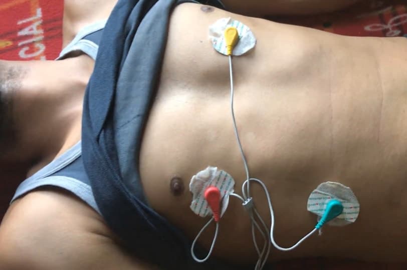
It is recommended to snap the sensor pads on the leads before application to the body. The closer to the heart the pads are, the better the measurement. The cables are color-coded to help identify proper placement.

Red: RA (Right Arm)
Yellow: LA (Left Arm)
Green: RL (Right Leg)
I have connected by ESP8266 with AD8232 to a Patient Chest or simply you can place it in your chest as shown in the figure below.
Source Code/Program for Serial Plotter
Here is a Source Code for viualizing the ECG graph waveform on Serial Plotter. Simply copy the code and upload it to the NodeMCU ESP8266 Board.
|
1 2 3 4 5 6 7 8 9 10 11 12 13 14 15 16 17 18 19 20 21 |
void setup() { // initialize the serial communication: Serial.begin(9600); pinMode(14, INPUT); // Setup for leads off detection LO + pinMode(12, INPUT); // Setup for leads off detection LO - } void loop() { if((digitalRead(10) == 1)||(digitalRead(11) == 1)){ Serial.println('!'); } else{ // send the value of analog input 0: Serial.println(analogRead(A0)); } //Wait for a bit to keep serial data from saturating delay(1); } |
Result & Observations
Once the code is upload, open the Serial Monitor and Set the Buad Rate to 9600. The ECG waveform can be seen below as a visualiations effect on Serial Monitor.

IoT based ECG Monitoring with AD8232 ECG Sensor & ESP8266
Using the above code you can visualize the ECG waveform on Serial Plotter Screen. But now we want to visualize the ECG waveform remotely from any part of the world. So for that, I won’t need to send the signal generated to any IoT platform. For that I used Ubidots. Using Ubidots you can send data to the cloud from any Internet-enabled device.

The complete guide for setting up Ubidots is explained in the video below. Follow the video guide below to setup Ubidots with ESP8266 & ECG Sensor Code.
Source Code/Program
The source code for IoT Based ECG Monitoring with AD8232 ECG Sensor & ESP8266 is given below. Copy this code and change the following Parameters.
- WIFI SSID: Your WiFi SSID
- PASSWORD: Your WiFi password
- TOKEN: Your Ubidots TOKEN (Check the video below to find about it)
- MQTT_CLIENT_NAME: Your own 8-12 alphanumeric character ASCII string.
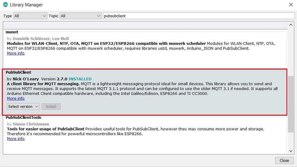
You need one library called Pubsubclient library. So go to the library manager and install the library as shown in the image below.
|
1 2 3 4 5 6 7 8 9 10 11 12 13 14 15 16 17 18 19 20 21 22 23 24 25 26 27 28 29 30 31 32 33 34 35 36 37 38 39 40 41 42 43 44 45 46 47 48 49 50 51 52 53 54 55 56 57 58 59 60 61 62 63 64 65 66 67 68 69 70 71 72 73 74 75 76 77 78 79 80 81 82 83 84 85 86 87 88 89 90 91 92 93 94 95 96 97 98 99 100 |
#include <ESP8266WiFi.h> #include <PubSubClient.h> #define WIFISSID "Alexahome" // Put your WifiSSID here #define PASSWORD "12345678" // Put your wifi password here #define TOKEN "BBFF-YKxITsj1YPeTMxw7mq8lvYFBpXnCxD" // Put your Ubidots' TOKEN #define MQTT_CLIENT_NAME "myecgsensor" // MQTT client Name, please enter your own 8-12 alphanumeric character ASCII string; //it should be a random and unique ascii string and different from all other devices /**************************************** * Define Constants ****************************************/ #define VARIABLE_LABEL "myecg" // Assing the variable label #define DEVICE_LABEL "esp8266" // Assig the device label #define SENSOR A0 // Set the A0 as SENSOR char mqttBroker[] = "industrial.api.ubidots.com"; char payload[100]; char topic[150]; // Space to store values to send char str_sensor[10]; /**************************************** * Auxiliar Functions ****************************************/ WiFiClient ubidots; PubSubClient client(ubidots); void callback(char* topic, byte* payload, unsigned int length) { char p[length + 1]; memcpy(p, payload, length); p[length] = NULL; Serial.write(payload, length); Serial.println(topic); } void reconnect() { // Loop until we're reconnected while (!client.connected()) { Serial.println("Attempting MQTT connection..."); // Attemp to connect if (client.connect(MQTT_CLIENT_NAME, TOKEN, "")) { Serial.println("Connected"); } else { Serial.print("Failed, rc="); Serial.print(client.state()); Serial.println(" try again in 2 seconds"); // Wait 2 seconds before retrying delay(2000); } } } /**************************************** * Main Functions ****************************************/ void setup() { Serial.begin(115200); WiFi.begin(WIFISSID, PASSWORD); // Assign the pin as INPUT pinMode(SENSOR, INPUT); Serial.println(); Serial.print("Waiting for WiFi..."); while (WiFi.status() != WL_CONNECTED) { Serial.print("."); delay(500); } Serial.println(""); Serial.println("WiFi Connected"); Serial.println("IP address: "); Serial.println(WiFi.localIP()); client.setServer(mqttBroker, 1883); client.setCallback(callback); } void loop() { if (!client.connected()) { reconnect(); } sprintf(topic, "%s%s", "/v1.6/devices/", DEVICE_LABEL); sprintf(payload, "%s", ""); // Cleans the payload sprintf(payload, "{\"%s\":", VARIABLE_LABEL); // Adds the variable label float myecg = analogRead(SENSOR); /* 4 is mininum width, 2 is precision; float value is copied onto str_sensor*/ dtostrf(myecg, 4, 2, str_sensor); sprintf(payload, "%s {\"value\": %s}}", payload, str_sensor); // Adds the value Serial.println("Publishing data to Ubidots Cloud"); client.publish(topic, payload); client.loop(); delay(10); } |
Results & Observations
Once the code is uploaded, you can open your serial Monitor. The Serial Monitor will display the following lines succesfully if the module is connected to Wifi and if Ubidots token is valid.
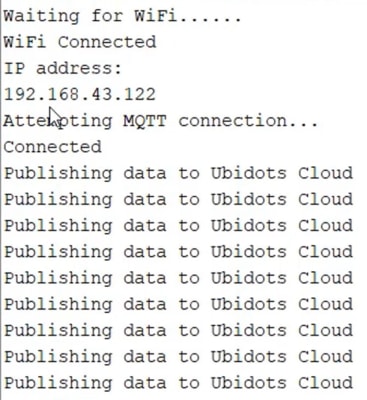
Now you can visit the Ubidots dashboard and you can observe the waveform being published on Ubidots. The waveform may not be exactly similar to above due to a little amount of delay. But it’s enough for a simple demonstration. In the near future, a better version of the device can be made.

Video Tutorial & Complete Guide

 & Live Dashboard")


3 Comments
where does the schematic draw?
Can you make a report on iot ecg monitoring system ?
i have tried your code but i got a problem in establishing the connection to UBIDOTS
Waiting for WiFi………..
WiFi Connected
IP address:
192.168.0.103
Attempting MQTT connection…
Failed, rc=-2 try again in 2 seconds
Attempting MQTT connection…
Failed, rc=-2 try again in 2 seconds
CAN U HELP ME?